

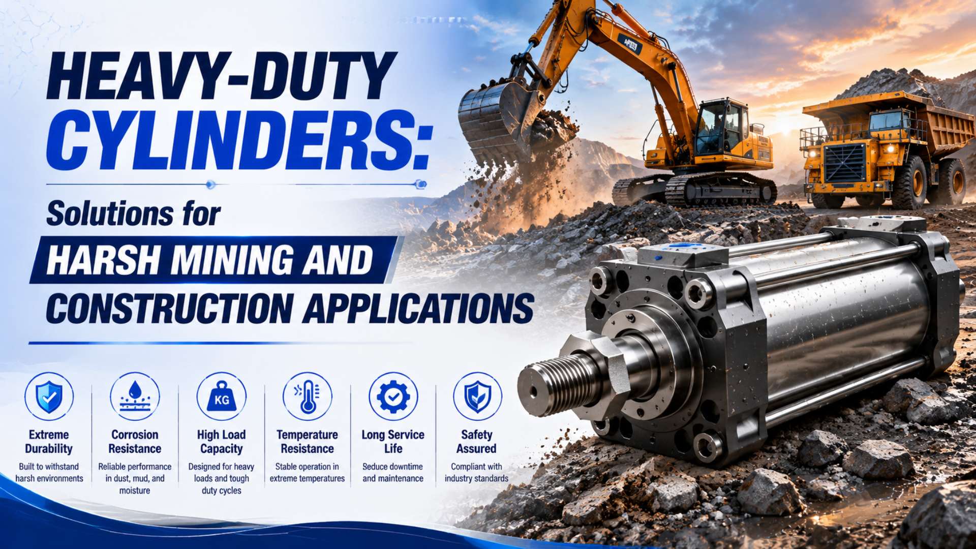
Heavy-duty pneumatic cylinders for mining and construction are not defined by a thicker tube, a black coating, or a marketing label. They are application-specific assemblies whose cylinder, mount, guide, seals, rod protection, fittings, sensors, air treatment, and maintenance plan have been matched to a documented duty profile. Selection starts with the hazards and load path, then ends with measurable acceptance evidence.
That distinction matters in mines, quarries, aggregate plants, concrete operations, earthmoving equipment, and temporary construction machinery. Dust may attack the exposed rod while water enters through damaged fittings. Cold can freeze residual moisture. Vibration can loosen a sensor bracket even when the cylinder barrel remains intact. A single “heavy-duty” claim cannot cover all of those failure paths.
Key Takeaways
- ISO 15552 covers bores from 32 to 320 mm, but it does not define a heavy-duty class
- Separate external contamination, dirty supply air, side load, end impact, corrosion, and temperature
- Approve the complete installed configuration, not an attractive cylinder body
- Set inspection and replacement triggers from evidence, not a universal calendar
What Does Heavy-Duty Mean for a Pneumatic Cylinder?
ISO 15552:2018 covers detachable-mount pneumatic cylinders with bores from 32 mm to 320 mm and rated pressure up to 1,000 kPa. Its purpose is dimensional interchangeability, not harsh-environment qualification or a universal heavy-duty rating (ISO 15552:2018, confirmed 2025).
A heavy-duty pneumatic cylinder is a cylinder configuration selected and verified for an application with demanding loads, contamination, temperature, corrosion, vibration, duty, access, or failure consequences. The term does not prove a particular wall thickness, rod hardness, seal life, shock limit, corrosion duration, or maintenance interval.
Define the term in the purchase specification. A useful definition identifies:
-
the exact cylinder model, bore, stroke, rod, mount, ports, cushioning, sensors, and accessories;
-
working and maximum pressure, speed, cycle rate, dwell, orientation, and load;
-
external forces and moments at retracted, mid-stroke, and extended positions;
-
dust, mud, water, chemicals, temperature, icing, sunlight, and corrosion exposure;
-
compressed-air purity and pressure-dew-point target at the point of use;
-
required inspections, service access, spare parts, and permitted repair method;
-
qualification sequence and measurable pass criteria.
This approach also exposes applications that should not be pneumatic. If available air pressure cannot provide the force margin, if a suspended load needs positive mechanical holding, or if speed and position must remain controlled through changing load, compare hydraulic, electromechanical, and pneumatic architectures before specifying a larger cylinder.
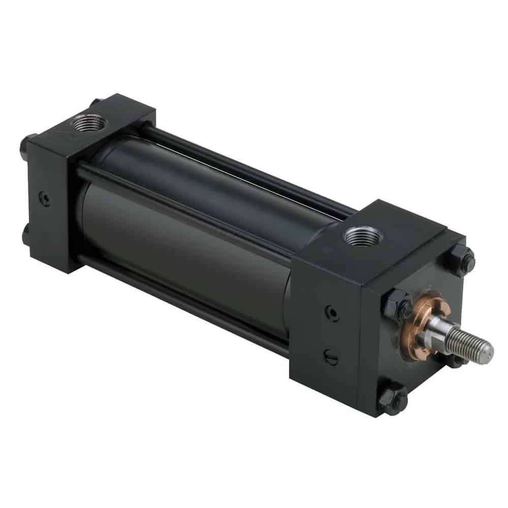
This product image shows a tie-rod construction and threaded rod end. Appearance alone does not establish its pressure, load, temperature, contamination, shock, or corrosion capability; those limits must come from the exact model documentation and application review.
How Should You Build the Mining or Construction Duty Profile?
The OSHA construction silica standard uses an action level of 25 micrograms per cubic metre and a permissible exposure limit of 50 micrograms per cubic metre as 8-hour time-weighted averages. Those are worker-exposure limits, not cylinder contamination ratings, but they show why site dust must be controlled rather than treated as ordinary dirt (OSHA, accessed July 26, 2026).
Describe the equipment location and operating state before choosing materials. “Outdoor quarry” is too broad. For example, the cylinder beside a wet crusher faces different hazards from one inside a filtered cab, beneath a concrete hopper, on a drill mast, or next to a salt-treated winter road.
Record each exposure in measurable terms where practical:
| Exposure | Data to collect | Selection consequence |
|---|---|---|
| Airborne dust | Material, source, concentration or observed deposition, particle control, cleaning method | Rod protection, scraper or bellows, enclosure, seal arrangement, inspection access |
| Mud and water | Splash, spray, immersion risk, pressure, direction, duration, drainage | Coatings, fasteners, rod material, sensor and connector protection, drain orientation |
| Temperature | Normal range, minimum start temperature, solar heating, rapid changes, dwell time | Seal compound, lubricant, clearances, sensor rating, air-drying requirement |
| Corrosive exposure | Chlorides, fertilizers, process chemicals, cleaning products, pH, contact time | Material pairings, coating system, isolation, rinse and inspection plan |
| Mechanical input | Payload, external force and moment, vibration spectrum, shock pulse, end-stop energy | Guide, mount, rod, fasteners, stops, cushion, assembly test |
| Duty | Speed, cycles, stroke distribution, dwell, pressure, shift pattern | Heat generation, lubrication, wear, air demand, reliability test profile |
| Failure consequence | Machine stop, falling load, personnel access, recovery time | Redundancy, guarding, lock, monitoring, spare strategy, validation depth |
NIOSH’s 362-page Dust Control Handbook for Industrial Minerals Mining and Processing covers dust-generating operations from drilling and crushing through screening, conveying, bagging, loadout, and transport (NIOSH, 2019). Use the site’s dust-control plan to understand where deposition will occur. Cylinder protection must support that plan, not create a new dust plume.
Severity comes from combinations. Fine dust plus an exposed lubricated rod may cause rapid deposition. The same dust with cold condensation can form an abrasive paste. Vibration may loosen a fitting and create the water-ingress path that later freezes. Review interactions, not just the maximum value in each row.
How Do You Separate External Contamination From Dirty Supply Air?
ISO 8573-1:2010 specifies compressed-air purity classes for 3 principal contaminant groups: particles, water, and oil. The classes apply independently of where air is specified or measured, so the RFQ must name the required class and the point of use instead of prescribing one generic filter size (ISO 8573-1, accessed July 26, 2026).
Treat contamination as three separate paths:
-
External ingress: dust, mud, water, or cleaning residue reaches the rod, scraper, sealing band, breather, connector, or damaged enclosure.
-
Supply-air contamination: particles, liquid water, water vapour, compressor oil, degraded hose material, rust, or desiccant dust arrives through the port.
-
Service-introduced contamination: dirt enters during tube cutting, fitting replacement, seal repair, lubrication, open-port storage, or field assembly.
The deposit location helps separate them. A packed ring outside the rod scraper points toward external exposure. Debris found in both cylinder chambers, valves, and downstream tubing points toward the air path. Clean replacement components that become contaminated immediately after maintenance suggest service practice.
Use controlled evidence rather than appearance alone:
-
collect point-of-use air samples under representative demand;
-
inspect filter differential pressure, drains, dryer status, branch piping, drops, and low points;
-
compare deposits from the rod side, cap side, tubing, valve, and external surface;
-
record installation state before cleaning or disassembly;
-
isolate and test leakage using the manufacturer’s approved method;
-
track failures by location, lot, configuration, exposure, and operating interval.
The pneumatic contamination case study provides a more detailed diagnostic boundary. Mining dust is different from wood dust, but the separation among external, supplied, and service-introduced contamination remains useful.
Load Path, Guidance, and Mounting
Standard gravity is exactly 9.80665 m/s², but a G value alone does not define force, pulse duration, frequency content, direction, or repetition. The installed mass and offset determine the reactions reaching the mount and guide (NIST Guide to the SI, accessed July 26, 2026).
Start with a load-path sketch. Include the machine frame, cylinder body, mount, piston rod or carriage, external guide, tooling, payload, stops, tubing, cable supports, and sensor brackets. Mark gravity, cylinder thrust, external force, side load, moments, commanded acceleration, base vibration, and end-stop reactions.
A larger bore increases available thrust, but it does not correct misalignment or create side-load capacity. The piston rod should transfer axial force unless the selected product explicitly carries lateral load. Use an external guide when the payload or machine geometry applies a transverse force or moment. The side-load mitigation guide explains the alignment and reaction checks.
Mount selection changes the load path:
-
centerline fixed mounts are generally suited to straight-line force transfer;
-
pivot mounts need aligned pins and freedom to follow the intended arc;
-
foot and side mounts require the frame and fasteners to resist torque and repeated shear;
-
long strokes need rod-column, sag, alignment, and support review;
-
attached manifolds, fittings, sensors, and cable brackets need their own vibration retention.
Parker’s mounting guidance recommends keying or pinning side-mounted cylinders for heavy or high-shock loads while avoiding restraint that prevents normal cylinder growth (Parker mounting information, accessed July 26, 2026). Apply the exact manufacturer’s instructions to the selected model and frame.
Keep shock and vibration calculations in the high-G cylinder selection guide. That article separates base excitation, moving-load inertia, and end-of-stroke impact. This guide focuses on how those results become an environmental cylinder specification.
Materials, Seals, and Surface Protection
One current Parker P1F cylinder catalog lists scraper and temperature options extending from -10°C to +150°C, depending on the exact configuration. That is an option-specific envelope, not proof that every polyurethane, FKM, NBR, scraper, lubricant, or assembled cylinder shares the same limit (Parker P1F catalog, accessed July 26, 2026).
Select materials as a system. Seal compound compatibility depends on temperature, pressure, speed, lubricant, media, surface condition, dwell, extrusion gap, and exposure time. A high-temperature elastomer may perform poorly at low-temperature startup or under abrasion. A hard scraper may protect the primary rod seal but damage a coating if the edge, preload, and finish are incompatible.
Specify the functional details:
-
rod base material, coating or treatment, finished hardness where relevant, surface finish, thickness, porosity, repair limits, and acceptance method;
-
primary rod seal, scraper or wiper, piston seal, static seals, wear rings, and cushion seals by compound or approved performance specification;
-
lubricant identity, quantity, compatibility, replenishment policy, and low-temperature behaviour;
-
barrel, end-cap, tie-rod, fastener, fitting, and sensor materials;
-
galvanic isolation and drainage where dissimilar metals become wet;
-
bellows or rod boot material, compressed and extended length, venting, abrasion clearance, and inspection access;
-
approved cleaning agents and prohibited chemicals.
Do not use rod hardness as the only mining criterion. A hard coating can still fail through cracking, poor adhesion, corrosion beneath a defect, incompatible finishing, or seal damage. The mining cylinder-rod coating guide covers carbide systems, surface finish, inspection, and repair decisions without reducing selection to one hardness number.
Salt-spray duration also needs context. ASTM B117-26 defines a controlled fog apparatus but does not prescribe a product-specific exposure duration or interpretation. ASTM further notes that stand-alone salt-spray results have seldom correlated with natural-environment performance (ASTM B117-26, 2026). State the specimen, preparation, test method, duration, evaluation criteria, allowable corrosion, and link to field exposure.
How Do Temperature, Water, and Corrosion Change the Design?
The ISO 8573-1 water class and pressure dew point describe supplied-air moisture, while the site minimum temperature defines the condensation and freezing margin. A dryer choice is therefore incomplete without the coldest pipe, valve, and cylinder conditions at the point of use (ISO 8573-1, accessed July 26, 2026).
For low-temperature service, verify:
-
ambient and compressed-air temperature during startup and operation;
-
pressure dew point at the actual operating pressure;
-
residual liquid-water traps, low points, drains, and outdoor branches;
-
seal, lubricant, tube, fitting, sensor, cable, and connector temperature ratings;
-
warm-up method, permitted no-load cycling, and cold-start acceptance;
-
clearance changes, breakaway pressure, leakage, response time, and cushioning after soak.
The sub-zero pneumatic cylinder guide explains why seal flexibility alone cannot prevent frozen condensate or lubricant-related response changes.
Water exposure needs a separate path review. A cylinder may survive rainfall while its downward-facing connector traps water, a boot retains mud, or a damaged cable jacket wicks moisture into a sensor. Provide drainage, avoid pockets, protect vulnerable ports, and place inspection points where personnel can reach them safely.
For corrosion, document the real electrolyte and contact cycle. Chloride splash, fertilizer dust, acid cleaning, alkaline concrete residue, and standing mine water do not produce the same attack. Review coating damage at threads, wrench flats, rod ends, fastener interfaces, sensor grooves, and mounting faces. Those discontinuities often matter more than the broad barrel surface.
Are Rodless Cylinders Better in Dusty Mining Applications?
Parker’s OSP-P operating instructions warn that dirt particles can lodge between the inner sealing band and cylinder bore and cause leakage. The same product family uses outer and inner sealing bands plus a carrier wiper system, proving that rodless performance depends on the exact sealing arrangement and maintenance conditions (Parker OSP-P instructions, accessed July 26, 2026).
Rodless cylinders remove an exposed piston rod and can reduce installed length. Those are useful benefits when a long stroke must fit inside a guarded machine. They do not make every rodless design fully enclosed or immune to abrasive dust, mud, water, corrosion, side load, or sealing-band damage.
Compare the actual mechanisms:
| Architecture | Potential advantage | Harsh-environment question |
|---|---|---|
| Rod cylinder | Simple axial force path; many scraper, boot, and material options | Can the exposed rod be guarded, cleaned, aligned, and inspected? |
| Mechanically coupled rodless | Full stroke in a shorter envelope; carriage supports modular guides | How are the slot, inner band, outer band, carrier wipers, and guide protected? |
| Magnetically coupled rodless | No mechanical slot through the tube | Is coupling force adequate, and how are the external carriage and guide sealed? |
| Guided cylinder or slide | Integrated resistance to specified forces and moments | Do catalog combined-load and environmental limits cover the installation? |
The choice turns on the installed load, available space, contamination direction, cleaning method, required guidance, seal access, and model-specific options. For example, a covered rod cylinder may outlast an exposed sealing-band actuator in one quarry. An enclosed rodless assembly may be the better solution in another.
Removing the piston rod changes the contamination path; it does not remove contamination from the design problem. The correct comparison counts every exposed moving interface, including carriage wipers, guide rails, sealing bands, cable carriers, boots, and sensor slots.
Qualification and RFQ Evidence
ISO 19973-3:2015 assesses rod-cylinder reliability through defined tests and reports lifetime in cycles or kilometres, not vague months in service. It also specifies test equipment and threshold levels, which illustrates why a meaningful life claim needs a configuration, test profile, failure definition, and sample basis (ISO 19973-3, confirmed 2021).
Build the RFQ from the duty profile. Include:
-
function, bore, stroke, force, pressure, speed, cycle rate, orientation, dwell, and expected life unit;
-
payload, tooling, centre-of-gravity coordinates, guide arrangement, external forces and moments, mounts, stops, and shock absorbers;
-
measured or specified shock and vibration inputs, operating state, axes, repetitions, and acceptance criteria;
-
dust, water, mud, chemicals, temperature, sunlight, corrosion, cleaning, and storage exposure;
-
ISO 8573-1 purity classes at the point of use and pressure-dew-point target;
-
required materials, seals, coatings, lubricant, scraper, boot, sensors, connectors, fittings, and protective enclosure;
-
traceability, inspection records, test reports, change notification, spare kits, repair instructions, and discontinuation notice.
Then qualify the installed configuration through staged gates:
Sample inspection confirms construction and workmanship. It does not reproduce quarry service. Installed testing should include the production mount, guide, payload, fittings, tubing, sensors, guards, cleaning method, and relevant operating states. Define leakage, stroke completion, breakaway, cycle time, position, temperature, fastener movement, coating damage, and sensor operation limits before testing.
ISO 4414:2010 covers pneumatic-system safety across design, installation, operation, maintenance, cleaning, reliability, energy efficiency, and environment (ISO 4414, confirmed 2021). Safety functions, suspended loads, stored energy, isolation, guarding, and maintenance access therefore belong in the machine risk assessment, not only the cylinder RFQ.
In our experience reviewing harsh-environment applications, the most useful RFQ is rarely the longest. It is the one that includes a marked-up installation drawing, photos of the contamination direction, minimum and maximum temperatures, payload geometry, current failure evidence, point-of-use air data, and explicit pass criteria. Those details reveal the weak interface faster than a generic request for a stronger cylinder.
What Maintenance Strategy Works in Dust, Mud, and Cold?
OSHA generally prohibits using compressed air to clean silica-contaminated clothing or surfaces unless effective ventilation captures the dust cloud or no alternative method is feasible. Wet methods and HEPA-filtered vacuuming are preferred where feasible (OSHA silica guidance, 2017).
Follow the machine risk assessment, site exposure-control plan, and cylinder manufacturer’s instructions. Do not create a dust cloud to make the rod look clean. If compressed air cleaning is permitted for a particular task, apply the relevant pressure, guarding, personal-protective-equipment, and dust-capture requirements.
Use condition and exposure to set maintenance frequency. Start with short intervals during commissioning, then adjust from evidence:
-
inspect the rod, scraper, boot, sealing band, guide, mount, fittings, tubing, sensors, and guards before cleaning;
-
photograph deposit patterns, corrosion, witness-mark movement, scoring, pitting, boot damage, loose hardware, and leaks;
-
drain and inspect air-treatment equipment and compare point-of-use air data with the specified classes;
-
trend stroke time, dynamic pressure, breakaway behaviour, leakage, cushion action, and position only when the measurement method is repeatable;
-
investigate a change before replacing parts on a calendar;
-
keep ports capped and repair parts clean during storage and service;
-
record the exact replacement seal kit, lubricant, configuration, lot, and repair findings.
Early inspection intervals should be conservative because the installation is unproven. A stable trend may support extending them. Increasing dust, cold starts, cleaning exposure, duty, or leakage should shorten them. Replace a scraper, seal, boot, bearing, or cylinder when its documented condition reaches the manufacturer or machine acceptance limit, not because a generic article says six months or one year.
Heavy-Duty Pneumatic Cylinder FAQs
ISO 4414 addresses pneumatic-system safety across the full machine lifecycle, while ISO 19973-3 reports rod-cylinder reliability in cycles or kilometres. Together they show why a heavy-duty selection needs installed safety controls and measurable service evidence rather than one label or calendar-life promise.
Is there an industry-standard definition of a heavy-duty pneumatic cylinder?
No single ISO class defines heavy-duty pneumatic cylinders by wall thickness, seal material, shock level, or service life. ISO 15552 defines dimensional interfaces for specified cylinders, while model data defines operating limits. Write the application’s load, environment, configuration, qualification, and maintenance requirements into the RFQ so “heavy-duty” has a project-specific meaning.
Are rodless cylinders always better in dusty mining equipment?
No. Rodless cylinders remove an exposed piston rod and reduce installed length, but mechanically coupled designs still have sealing bands, carrier wipers, and exposed guide interfaces. Parker’s OSP-P instructions acknowledge that particles can lodge near the inner band and cause leakage. Compare the exact contamination path, protection options, guide loads, and service access.
Which seal material is best for mining and construction cylinders?
There is no universal best compound. Select the rod seal, scraper, piston seal, static seals, cushion seals, lubricant, and rod finish as a compatible system. Temperature, speed, pressure, dust, water, chemicals, dwell, extrusion gap, and cleaning agents all matter. Require the supplier to approve the complete configuration and its operating envelope.
How dry must the compressed air be for sub-zero cylinder service?
Specify particle, water, and oil purity at the point of use using ISO 8573-1, then set pressure dew point with margin below the coldest expected component and pipe temperature. Confirm the dryer, drains, outdoor branches, startup state, and pressure. A filter micron rating alone cannot prevent residual water from freezing inside the system.
How often should a heavy-duty cylinder be inspected or rebuilt?
Begin with conservative inspections during commissioning and adjust them from measured exposure, condition, duty, leakage, motion, and manufacturer limits. Dust deposition, cold starts, washdown, shock, and maintenance access vary too much for one universal interval. Record findings before cleaning, define rejection limits, and replace components when evidence reaches the approved threshold.
Sources and technical references
- ISO 15552:2018, Pneumatic fluid power cylinders with detachable mountings, confirmed 2025; retrieved July 26, 2026.
- ISO 8573-1:2010, Compressed air contaminants and purity classes, retrieved July 26, 2026.
- ISO 4414:2010, Pneumatic fluid power general rules and safety requirements, confirmed 2021; retrieved July 26, 2026.
- ISO 19973-3:2015, Assessment of pneumatic cylinder reliability by testing, confirmed 2021; retrieved July 26, 2026.
- OSHA, Respirable Crystalline Silica in Construction, retrieved July 26, 2026.
- OSHA, Interim Enforcement Guidance for Silica in Construction, 2017; retrieved July 26, 2026.
- NIOSH, Dust Control Handbook for Industrial Minerals Mining and Processing, 2019; retrieved July 26, 2026.
- ASTM B117-26, Standard Practice for Operating Salt Spray Apparatus, 2026; retrieved July 26, 2026.
- Parker, OSP-P Operating Instructions, retrieved July 26, 2026.
- Parker, P1F Pneumatic Cylinders Catalog, retrieved July 26, 2026.
- Parker, Pneumatic Cylinder Mounting Information, retrieved July 26, 2026.