

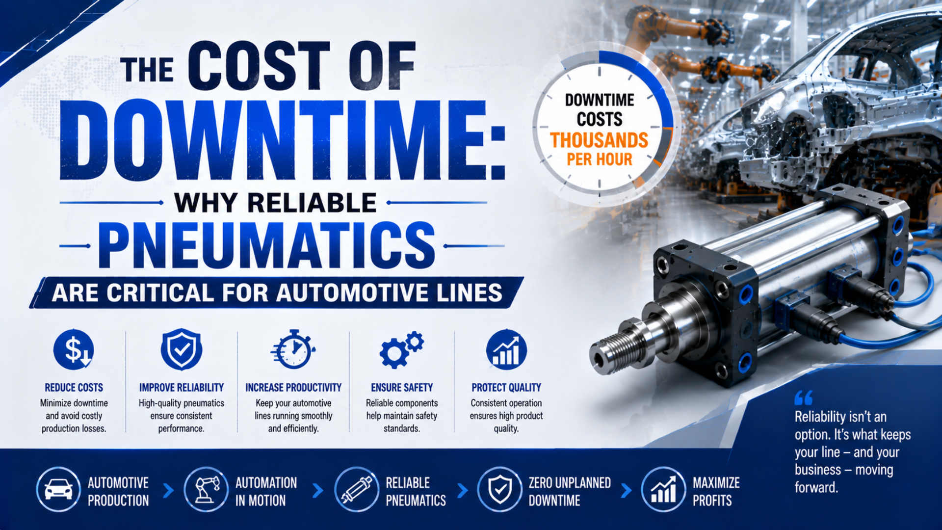
Pneumatic reliability matters on automotive lines because one clamp, lift, transfer, or valve can sit on the production critical path. The right objective isn’t to claim that a cylinder will never fail. It is to prevent avoidable failures, detect deterioration early, isolate energy safely, restore the function quickly, and stop the same fault from returning.
This changes the buying question. Unit price still matters, but a defensible decision also considers application fit, diagnostic access, documented replacement equivalence, local spares, safe changeover time, and proof testing. Those factors influence both failure probability and mean time to repair.
Key Takeaways
- Siemens’ survey of large automotive manufacturers estimated unplanned downtime at USD 2.3 million per hour, but each plant needs its own cost model.
- Rank pneumatic functions by production consequence, not component price.
- Reduce exposure through condition checks, safe isolation, qualified spares, rehearsed recovery, and recurrence control.

Publisher information and a route for technical corrections are available through About Us and Contact.
What Does Automotive Downtime Really Cost?
Siemens’ 2024 survey of large automotive manufacturers estimated unplanned downtime at USD 2.3 million per hour, twice its 2019 estimate (Siemens Senseye, 2024). Treat that figure as a large-manufacturer benchmark, not a universal rate for every plant or every pneumatic fault.
Downtime cost begins with lost contribution during the stopped interval. It can also include idle labor, scrapped work in progress, containment and restart work, premium freight, missed-sequence costs, and customer penalties. Some events affect one station; others block an entire linked line. The boundary must be explicit before anyone attaches a cost to it.
What, exactly, did the stoppage prevent the plant from producing?
Component price and downtime exposure are different variables. A modest valve, sensor, fitting, or cylinder can carry a high consequence when no buffer, bypass, or parallel station exists. Conversely, an expensive actuator may have low production impact if the machine can isolate that operation and continue safely.
Use three scopes when reporting an event:
- Station loss: the affected machine cannot complete its cycle.
- Line loss: upstream or downstream interlocks stop dependent stations.
- Business loss: missed volume creates recovery shifts, logistics expense, or customer impact.
The Siemens report focuses on large manufacturers and combines several cost categories. A plant should therefore use its own verified throughput, margin, labor, scrap, and contract data for approvals. Copying an industry headline into an ROI worksheet can exaggerate a small event or understate a bottleneck failure.
How Should a Plant Calculate a Pneumatic Downtime Event?
The same Siemens study reports a USD 2.3 million hourly automotive benchmark, yet its surveyed population is weighted toward large manufacturers (Siemens Senseye, 2024). A useful pneumatic event model replaces that headline with plant-specific values and keeps time-based losses separate from one-time recovery costs.
Start with a transparent equation:
Here, is the total event cost in the plant’s currency. The downtime duration is measured in hours, and is the validated loss per stopped hour. The remaining terms cover scrapped material, recovery work, premium freight, and contractual penalties. Use zero when a category genuinely doesn’t apply.
Where should the event clock stop? At stable, accepted production, not merely when the actuator moves again.
Separate the timeline as well. Detection time starts when the fault becomes visible and ends when the failed function is identified. Isolation and access time covers the approved energy-control process and physical access. Repair time covers the change itself. Verification and ramp-up continue until the process produces accepted parts at the intended rate.
| Time segment | Start and finish | Evidence to capture |
|---|---|---|
| Detection | Abnormal condition to identified failed function | Alarm history, pressure trend, sensor state, cycle signature |
| Safe isolation and access | Diagnosis to verified zero-energy work condition | Approved procedure, isolation points, stored-energy check |
| Repair | Work begins to mechanical and electrical completion | Replaced part, cause found, settings, measurements |
| Proof and ramp-up | Repair completion to accepted stable production | Leak test, dry cycles, guarded run, quality approval |
Which Pneumatic Functions Are Production-Critical?
NIST found that the most reactive quarter of surveyed manufacturers was associated with 3.3 times more downtime than the least reactive quarter (NIST, updated 2025). For an automotive line, criticality ranking directs limited inspection, monitoring, and spares effort toward pneumatic functions with the greatest production consequence.
Rank the function first, then its components. “Clamp body side before weld” is a function. The cylinder, valve, sensors, regulator, tubing, fittings, interlocks, mount, and logic that make it happen form the failure chain. Replacing a cylinder alone won’t correct a valve-flow restriction, side loading, low local pressure, or a damaged sensor cable.
Why start with the function? Production loses the operation, not an isolated catalog number.
A practical criticality review asks five questions:
- Does loss of the function stop one machine, a whole line, or only a redundant path?
- Is there a safe manual method, buffer, bypass, or parallel station?
- How quickly can the failed function be isolated and identified?
- Is a configured and approved replacement available at the plant?
- What verification is required before released production can resume?
The review should include standard and rodless cylinders, rotary actuators, grippers, valve manifolds, air-preparation units, pressure switches, position sensors, tubing, and fittings. Rodless designs can solve a space or guidance problem, but they are not automatically more reliable. Suitability depends on load moments, speed, cushioning, contamination, alignment, duty, and the exact construction.
For component-level inspections, use a documented pneumatic actuator maintenance checklist and tie every check to a failure mode. A checklist without a decision threshold creates activity, not reliability.
What Failure Modes Actually Stop Automotive Lines?
NIST associated heavy reliance on reactive maintenance with 16.0 times more defects than low reliance in its manufacturing survey (NIST, updated 2025). Pneumatic line stops usually develop through leakage, friction, contamination, pressure or flow loss, misalignment, impact, sensing faults, or control faults rather than one universal cylinder weakness.
| Observed symptom | Plausible causes to test | Useful evidence |
|---|---|---|
| Slow or incomplete stroke | Low dynamic pressure, restricted exhaust, undersized valve or tube, rising seal friction, external binding | Pressure at both ports during motion, stroke time, exhaust condition |
| Position not confirmed | Sensor movement, cable damage, magnet issue, mechanical overtravel, logic fault | Sensor state at cylinder and controller, measured stop position |
| Repeated seal leakage | Contamination, damaged surface, incompatible seal, side load, poor alignment, excessive speed | Leak location, surface inspection, load geometry, cycle conditions |
| Hard end impact | Excess speed, inadequate cushioning, changed mass, lost back pressure | Moving mass, stroke time, cushion setting, impact signature |
| Intermittent stall | Marginal force, pressure sag, guide binding, valve response, exhaust restriction | Dynamic pressure, load direction, guide force, valve command and response |
Diagnosis should follow the air path and load path. Confirm the supply at rest and during motion. Check commanded valve state and exhaust. Separate actuator friction from external machine binding. Inspect mounts and guidance. Then check the sensor and control sequence. Swapping parts before the fault is isolated can erase evidence and introduce a second problem.
Where should diagnosis begin? At the first measurable difference between the command and the physical response.
Early indicators are useful only when tied to action limits. Trending stroke time, end-position timing, dynamic pressure, leakage, or impact can reveal change, but no single threshold fits every application. This guide to predictive-maintenance indicators explains how to connect condition evidence with spare-parts timing.
Build Reliability Around Detection, Isolation, and Recovery
Among establishments relying mainly on preventive and predictive maintenance, NIST associated heavier predictive use with 15% less downtime (NIST, updated 2025). The lesson isn’t to instrument every cylinder. It is to detect meaningful deterioration on critical functions and prepare the safe recovery path before a stoppage.
Reliability work has two different levers. Better application engineering, clean air, alignment, load control, and condition-based maintenance reduce the chance of failure. Diagnostics, isolation design, access, qualified spares, instructions, and training reduce the duration after failure. A supplier’s stock position mainly affects the second lever.
Which lever is weak: failure prevention, or recovery after failure?
Build the control plan in this order:
- Detect: define the signals that distinguish normal variation from deterioration.
- Diagnose: provide pressure test points, drawings, I/O identification, and an evidence sequence.
- Isolate: identify every energy source and the stored pneumatic or mechanical energy.
- Restore: keep the approved configuration, tools, seals, fittings, and settings available.
- Prove: run leak, motion, interlock, and quality checks before release.
- Learn: record the physical cause and update the prevention plan.
How Should Critical Spares and Qualified Alternatives Be Planned?
IATF FAQ 29 identifies five elements for effective contingency planning: risk analysis, contingency development, alternative measures, regular testing and validation, and customer-specific compliance (IATF, 2022). Pneumatic spares should support that tested plan, not become an unverified collection of parts with similar dimensions.
Create the spare from the approved machine configuration. Record the full part code, bore, stroke, pressure range, ports, mounting pattern, rod or carriage interface, cushioning, sensors, cable and connector, environmental limits, and any safety-related function. For rodless cylinders, add load orientation, permitted moments, guidance arrangement, carriage geometry, and coupling or sealing construction.
An alternative is qualified only after the interfaces and performance limits have been checked. Matching bore and stroke is not enough. Compare:
What makes the spare real? Evidence that it restores the approved function under representative conditions.
- mounting and datum dimensions;
- working pressure and force or thrust requirements;
- allowable loads and moments;
- port size, orientation, and flow needs;
- speed, cushioning, and impact-energy limits;
- sensing method and electrical interface;
- materials, lubricant, contamination, temperature, and cleaning exposure;
- maintenance access and replacement procedure.
First-article testing should reproduce the intended load, speed, cycle sequence, interlocks, and acceptance criteria. Document necessary adapters or setting changes. A true “drop-in” replacement requires evidence that no uncontrolled mechanical, pneumatic, electrical, software, or safety change remains.
For a structured supplier decision, see the automotive cylinder-brand qualification gates and the OEM-versus-aftermarket total-cost framework. Price and availability belong in the decision, but only after technical equivalence is established.
Safe Recovery and Proof Before Restart
OSHA 29 CFR 1910.147 requires periodic inspection of an energy-control procedure at least annually and includes pneumatic energy within its scope (OSHA). Fast recovery cannot bypass isolation, stored-energy control, or verification; those steps protect people while making restart quality more repeatable.
The machine-specific procedure governs the work. In general, authorized personnel identify every energy source, shut down the equipment, isolate and lock out the sources, relieve or restrain stored energy, and verify isolation before maintenance begins. Pneumatic pressure can reaccumulate, and elevated or spring-loaded mechanisms may retain mechanical energy after the gauge reads zero. After repair, inspect the work area and restore guards, tubing, wiring, fasteners, settings, and mechanical supports. Confirm personnel are clear, remove locks under the approved procedure, and notify affected employees. Then use a staged proof:
Can the line restart as soon as the part moves? No. Motion is only one acceptance check.
- Check the repaired assembly at zero or reduced energy where the procedure allows.
- Pressurize under controlled conditions and inspect for leakage or unintended movement.
- Run dry cycles at controlled speed while checking sensors, interlocks, cushioning, and sequence.
- Run guarded production trials and verify part quality.
- Release the station only when the defined acceptance criteria are met.
ISO 4414 covers pneumatic-system safety and asks designers to consider reliable operation, maintenance, and uninterrupted system operation (ISO 4414, confirmed 2021). Good access, labeled isolation points, test ports, and serviceable mounting are therefore design issues, not merely maintenance conveniences.
Reliability Metrics That Prevent Repeat Failures
NIST estimated that 45.7% of maintenance in its U.S. manufacturing survey was reactive, and the most reactive establishments were associated with 3.3 times more downtime (NIST, updated 2025). Automotive pneumatic reviews should track recurrence and recovery quality, not just count completed work orders.
Use a small set of measures tied to action:
What should a metric change? A design, limit, spare, instruction, training step, or escalation path.
| Measure | What it reveals | Decision it should support |
|---|---|---|
| Event count by failed function | Repeat faults and weak stations | Engineering correction or redesign priority |
| Detection time | Alarm and diagnostic effectiveness | Add test points, trends, or better fault logic |
| Safe isolation and access time | Maintainability of the installation | Improve approved access and procedure clarity |
| Repair time | Skill, tooling, instruction, and spare fit | Training, kitting, or work-instruction changes |
| Verification and ramp-up time | Restart and quality-control effectiveness | Improve proof plan and acceptance criteria |
| Recurrence within a defined interval | Whether the physical cause was removed | Escalate from replacement to root-cause action |
Mean time to repair can hide the wrong behavior if the event boundary is vague. A team that records only wrench time may appear fast while diagnosis, safe isolation, quality approval, and ramp-up remain invisible. Keep those segments separate. That makes investment decisions sharper and prevents a supplier lead-time change from being credited for unrelated process improvements.
Component life also needs statistical discipline. ISO 19973-1 states that pneumatic component service life varies and uses statistical evaluation to interpret reliability tests (ISO 19973-1, 2015). A universal three-year or five-year cylinder life is therefore not a sound maintenance rule. Use application conditions, manufacturer data, inspection results, and local failure history.
Reliable Pneumatics Shorten the Event, Not Just Component Life
NIST estimated USD 119.1 billion in preventable maintenance-related losses across the U.S. manufacturing scope it studied for 2016, including USD 18.1 billion attributed to downtime (NIST, updated 2025). The figures are broad, but they show why disciplined maintenance deserves engineering attention.
So what makes a component reliable in production? Its verified fit within that complete system.
Reliable automotive pneumatics come from the system around the component. Correct sizing, alignment, clean air, flow capacity, cushioning, load control, sensing, and maintenance lower the probability of failure. Criticality analysis, diagnostics, safe isolation, qualified spares, access, and proof testing control the duration and consequence when a failure still occurs. This is why no supplier should promise that a rodless cylinder, standard cylinder, or valve alone will eliminate downtime. The better question is measurable: does the approved configuration reduce failure risk, reveal deterioration, support safe work, restore the function quickly, and pass a defined production acceptance test?
Automotive Pneumatic Downtime FAQs
Siemens’ surveyed large automotive manufacturers estimated USD 2.3 million per hour of unplanned downtime, while NIST associated heavy reactive maintenance with 3.3 times more downtime (Siemens Senseye, 2024; NIST, updated 2025). These answers turn those broad findings into plant-specific pneumatic decisions.
How much does a pneumatic failure cost an automotive plant?
There is no universal amount. Measure stopped time and apply the plant’s validated time-loss rate, then add applicable scrap, recovery, premium-freight, and penalty costs. Siemens’ USD 2.3 million hourly automotive estimate reflects surveyed large manufacturers, so it is a benchmark rather than a substitute for the plant’s event records.
Are rodless cylinders inherently more reliable than rod cylinders?
No. A rodless cylinder can reduce installation length and may fit certain transfer duties well, but reliability depends on construction and application conditions. Check load moments, guidance, alignment, contamination, pressure, speed, cushioning, duty, and maintenance access. This magnetic rodless cylinder guide explains one construction type.
Which pneumatic spare parts should an automotive plant hold?
Hold approved spares for functions whose loss has high production consequence and poor recovery options. Base the list on machine configuration, failure history, supplier lead time, repairability, and contingency testing. Include the complete interface specification. A physically similar cylinder or valve is not a qualified spare until compatibility and acceptance testing are documented.
Can a qualified aftermarket cylinder be used as an emergency replacement?
Yes, when engineering has verified mechanical, pneumatic, electrical, performance, environmental, and safety interfaces before the emergency. Record any adapter, setting, logic, or work-instruction change and complete a representative first-article test. Brand category alone proves neither equivalence nor inferiority; the configured evidence and acceptance result decide suitability.
What is the safest way to restart after pneumatic repair?
Follow the machine-specific energy-control and restart procedure. Verify isolation before work, restore guards and connections, inspect the area, then reenergize under controlled conditions. Check leakage, unintended movement, sensors, interlocks, cushioning, sequence, and part quality through staged trials. OSHA 1910.147 governs hazardous-energy control during covered servicing.
Sources and technical references
- Siemens Senseye, The True Cost of Downtime 2024, large-manufacturer downtime estimates and cost categories; 2024, retrieved 2026-07-26.
- NIST, Research Suggests Significant Benefits to Investing in Advanced Machinery Maintenance, manufacturing maintenance associations and estimated losses; updated 2025, retrieved 2026-07-26.
- NIST, Manufacturing Machinery Maintenance, reactive, preventive, and predictive maintenance findings; updated 2025, retrieved 2026-07-26.
- IATF 16949:2016 FAQ 29, contingency-plan guidance; 2022, retrieved 2026-07-26.
- ISO 4414:2010, pneumatic-system safety and reliable-operation scope; confirmed 2021, retrieved 2026-07-26.
- ISO 19973-1:2015, statistical assessment of pneumatic component reliability; retrieved 2026-07-26.
- OSHA 29 CFR 1910.147, control of hazardous energy during covered servicing; retrieved 2026-07-26.