

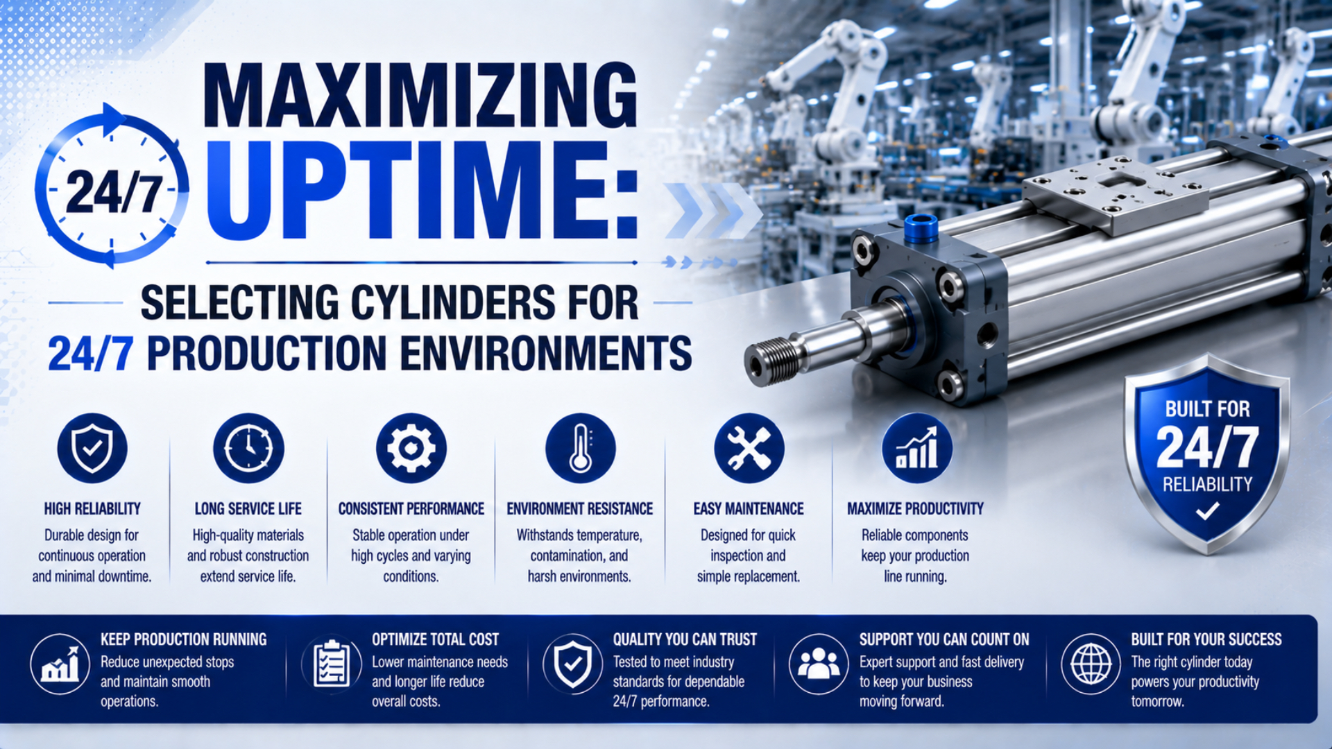
A pneumatic cylinder is suitable for 24/7 production only when its exact configuration fits a measured duty profile and can be maintained within the available service window. “Heavy duty” is not a universal reliability grade. Start with annual cycles, travel, load path, stopping energy, environment, air quality, and the consequence of failure.
This changes the buying question. Instead of asking which cylinder lasts longest, ask which cylinder has documented limits that cover the application, which evidence supports its reliability claim, and how quickly the plant can detect, isolate, and recover from a fault. Uptime comes from the whole decision, not one seal material or marketing label.

A cylinder used around the clock still needs application-specific limits for load, speed, cushioning, air quality, environment, and maintenance access.
Key Takeaways
- ISO 19973-3 expresses pneumatic-cylinder life in cycles or kilometres, not a universal number of years.
- Convert the production schedule into annual cycles and travel before requesting reliability evidence.
- Check load moments, cushion energy, dynamic pressure, environment, repair access, and spare strategy together.
- Approve the cylinder against a recorded commissioning baseline.
24/7 cylinder duty is the measured cycles, travel, load, motion, environment, and maintenance exposure assigned to an actuator. A commissioning baseline is the controlled set of healthy measurements used for later comparison. The recovery time objective is the longest acceptable interval from a detected fault to validated production restart.
What Does 24/7 Duty Mean for a Pneumatic Cylinder?
Twenty-four-hour availability does not mean every cylinder moves continuously. SMC lists 15 Hz at a 5 mm stroke for one CQ2 high-frequency configuration and 12 Hz at a 25 mm stroke for one CM2 configuration (SMC, 2026). Those limits show why “24/7” must become measurable exposure.
Record one complete cycle precisely: extend, dwell, retract, and dwell. Then capture scheduled hours, operating days, utilization, stroke, moving mass, orientation, acceleration, external stops, and fault recovery. A line that is staffed around the clock may still have long dwell periods. Another axis may reverse several times per second.
Annual cycles can be estimated as:
Here, is cycles per year, is cycles per minute, is scheduled operating hours per day, is operating days per year, and is the measured utilization fraction. Use production history for when possible rather than assuming the machine moves for every scheduled minute.
Annual sliding distance is often more informative than cycles alone:
Here, is round-trip travel in kilometres when stroke is entered in metres. For an illustrative application at 6 cycles/min, 20 h/day, 350 days/year, and 85% utilization, the result is 2,142,000 cycles/year. A 0.5 m stroke produces 2,142 km/year.
ISO 19973-3 notes that pneumatic-cylinder lifetime is normally expressed in cycles or kilometres (ISO 19973-3, 2015). For a deeper explanation of duty definitions, see how linear-actuator duty cycle is calculated.
Which Cylinder Architecture Best Protects Uptime?
The right architecture follows the load path and machine layout. ISO 15552 covers interchangeable mounting dimensions for detachable-mounting cylinders from 32 to 320 mm bore and up to 1,000 kPa rated pressure (ISO 15552, confirmed 2025). Dimensional interchangeability helps recovery, but it does not prove equivalent load, cushioning, or life.
| Application condition | Architecture to evaluate | Uptime question |
|---|---|---|
| Axial push or pull with an externally guided load | Standard rod cylinder | Can the guide prevent side load and rotation at every position? |
| Tooling applies offset force or moment | Guided cylinder or separate linear guide | Are pitch, yaw, and roll moments inside the selected guide limits? |
| Long stroke with limited installation length | Mechanically coupled or magnetic rodless cylinder | Can the carriage, guide, sealing system, and coupling carry the dynamic load? |
| Short stroke in restricted space | Compact cylinder | Is there enough bearing support, cushioning, and service access? |
| Washdown, chemicals, heat, or clean production | Environment-specific construction | Are every seal, lubricant, sensor, fastener, and surface compatible? |
A rod cylinder is a poor guide rail. If the machine transmits a transverse force or overturning moment into the rod bearing, increasing seal quality does not correct the load path. Review the mechanics of cylinder side loading before choosing bore or seal material.
Rodless cylinders solve installation-length problems, but they do not eliminate load moments. Mechanically coupled designs have sealing bands and carriage guides; magnetic designs have coupling-force limits and can decouple. Long-stroke axes may also need separate guidance and structural support. The rodless-cylinder family comparison explains those distinctions.
Treat architecture selection as failure containment. If a cylinder sticks, leaks, decouples, or loses a sensor, determine whether the load remains supported and whether the machine moves to a safe state. A component that is easy to replace but allows an unsupported vertical load to fall is not an uptime solution.
Which Catalog Limits Control High-Cycle Operation?
Catalog limits must be checked as a set. The SMC high-frequency examples list 2,500 mm/s maximum piston speed, but they also restrict bore, stroke, pressure, temperature, cushion type, and recommended circuit conditions (SMC, 2026). A speed number alone cannot qualify the application.
Ask the supplier for the exact ordering code and verify:
- working and proof pressure;
- minimum pressure at the cylinder during motion;
- piston-speed range and maximum operating frequency;
- allowable kinetic energy or moving mass at the relevant speed;
- axial force plus allowable radial load and guide moments;
- ambient and fluid temperature for the complete assembly;
- stroke tolerance, mounting orientation, and sensor restrictions;
- permitted air quality and lubrication condition;
- maintenance actions allowed during any life test.
Never combine the best value from several variants. A high-temperature seal option may change speed, friction, lubricant, sensor, pressure, or cycle-life limits. A longer stroke can also lower the permitted frequency even when bore and pressure remain unchanged.
For rodless-specific supplier evidence and pilot-test questions, use the companion guide to evaluating rodless-cylinder durability for 24/7 operation.
Cushioning and Load Control Are Reliability Decisions
End-of-stroke energy must be absorbed on every cycle. SMC publishes kinetic-energy limits from 0.16 to 0.98 J across the specific CM2/CQ2 high-frequency variants in its example catalog (SMC, 2026). Those small, model-dependent values make moving mass and impact speed selection-critical.
The cylinder cushion does not merely quiet the machine. It must decelerate the moving mass while the actuator is still applying force. Available capacity depends on the exact bore, cushion design, pressure, cushion stroke, speed at cushion entry, and adjustment. Average stroke speed can hide a much faster final approach.
Use an external shock absorber or a controlled motion profile when the internal cushion cannot absorb the event with margin. Keep the hard stop and guide structure out of the cylinder rod whenever possible. After adjustment, record cushion-screw positions, stroke time, rebound, sound, and end-cap temperature so maintenance has a healthy reference.
For adjustment symptoms and cushion-entry velocity, see the role of air cushions in high-speed cylinder applications.
How Should Air Quality and Environment Enter the Selection?
Compressed-air quality must be specified at the point of use. ISO 8573-1 classifies purity by 3 principal contaminant groups: particles, water, and oil (ISO 8573-1, 2010, revision planned). A filter micron rating alone does not define the air reaching the cylinder.
Match the cylinder, valves, tubing, and preparation system to the same requirement. Record pressure dew point, particle class, oil condition, ambient temperature, media temperature, cleaning chemicals, washdown pressure, and ingress exposure. If the supplier requires non-lubricated air, adding an upstream lubricator later can create inconsistent lubricant conditions and complicate servicing.
“Stainless steel” and “food grade” are incomplete descriptions. Buyers need the material grades and locations, seal and lubricant declarations, surface-finish limits where hygiene matters, and cleaning-agent compatibility. A sensor or cable may have a lower temperature or washdown rating than the cylinder body.
Use the air-source treatment guide to connect the purity requirement to filters, regulators, drains, dryers, and point-of-use measurement.
Maintainability, Standardization, and Spare Strategy
Standard interfaces can shorten recovery without claiming longer component life. ISO 15552 defines basic, mounting, and accessory dimensions for 32–320 mm detachable-mounting cylinders at up to 1,000 kPa (ISO 15552, confirmed 2025). Interchangeable dimensions still require verification of rod thread, ports, sensors, force, cushioning, and dynamic performance.
Design the axis so technicians can reach mounting bolts, ports, sensor screws, cushion adjusters, and energy-isolation points without dismantling unrelated equipment. Capture the exact cylinder ordering code, mount, rod-end accessory, sensor, connector, seal kit, lubricant, and adjustment settings in the asset record.
Choose spare depth by consequence and restoration time:
- stock a complete preconfigured cylinder when one failed axis stops a critical line and an in-place rebuild cannot fit the recovery target;
- stock a service kit when the cylinder can be removed safely, rebuild capability is proven, and another asset or buffer covers the repair time;
- stock wear parts centrally when several standardized axes share the exact compatible parts;
- avoid “near match” spares whose ports, sensors, cushion, rod thread, or materials differ.
The most useful standardization target is not the cylinder alone. Standardize the replacement task: isolation method, mounting datum, tube and electrical connectors, lifting requirement, tools, acceptance test, and stored settings. That reduces variation during a stressful recovery even when two axes need different bores or strokes.
Condition signals should trigger diagnosis, not automatic parts orders. A slower stroke can result from supply pressure, a restricted valve, tubing, load, alignment, exhaust restriction, or cylinder wear. The guide to pre-ordering cylinder spare parts from condition evidence covers that diagnostic boundary.
What Supplier Evidence Supports a Reliability Decision?
A reliability claim needs disclosed test conditions and individual results. ISO 19973-1 provides general procedures, calculation, reporting, and statistical evaluation for first failure without repair, with stated treatment of outliers (ISO 19973-1, 2015). A single headline cycle count cannot show whether the application matches the test.
Request a compact evidence package:
- exact tested ordering codes and sample quantity;
- load, load offset, orientation, stroke, speed, frequency, pressure, temperature, and air quality;
- valve, tubing, cushioning, external stops, guides, sensors, and lubrication condition;
- maintenance, adjustment, suspension, and replacement actions allowed during the test;
- failure definition, threshold levels, individual results, outliers, and suspended tests;
- difference between the tested specimen and the proposed production configuration.
ISO 19973-3 applies specifically to single- and double-acting cylinders with piston rods and includes test procedures and threshold levels (ISO 19973-3, 2015). For rodless or specialized designs, ask the supplier to explain the method used and why it represents the proposed application.
Do not convert laboratory results directly into calendar years unless annual cycles, annual travel, load, environment, and permitted maintenance all align. A useful supplier answers the differences. A vague promise of “millions of cycles” leaves the engineering risk with the buyer.
How Do You Commission a Cylinder for Reliable Production?
Commissioning turns the selected limits into a measurable baseline. OSHA 1910.147 requires hazardous-energy isolation, relief or restraint of stored energy, and verification before servicing begins on machinery (OSHA). Build those controls into access, troubleshooting, adjustment, and replacement procedures before production release.
Run acceptance tests at the worst credible operating condition, not only during an unloaded dry cycle. Measure:
- static supply pressure and dynamic pressure at the valve or cylinder;
- extend, dwell, retract, and total cycle time;
- payload, orientation, tooling offset, and product variation;
- cushion-entry behavior, rebound, hard-stop contact, and abnormal noise;
- external leakage and repeatable pressure-decay conditions where applicable;
- cylinder, end-cap, guide, valve, and nearby ambient temperature after thermal stabilization;
- sensor switching position and margin;
- mounting alignment, fastener condition, tubing restraint, and guide freedom.
Keep the baseline with the asset record and specify the operating state used for each measurement. After repair or adjustment, repeat the same acceptance test. Update the baseline only when the changed configuration has been reviewed and approved.
How Should You Calculate Site-Specific Downtime Risk?
Use plant records instead of generic downtime-cost ranges. ISO 4414 is a 38-page system standard that explicitly considers uninterrupted operation, maintenance economy, reliable operation, energy efficiency, and environment (ISO 4414, 2010). Keep each event-cost input separate so finance and operations can review it without a hidden industry average.
A transparent event model is:
Here, is the site-specific cost of one event, is verified downtime duration, is lost production contribution per hour, is idle or additional labor per hour, is scrap or downstream loss per hour, is repair cost, and is any documented expedite or penalty cost.
Do not count revenue as profit, and do not count the same labor twice. Use a range where throughput, recovery time, or contribution is uncertain. Then compare the expected risk reduction with the price, validation cost, spare inventory, and changeover effort for each option.
Criticality also changes the decision. A low-cost cylinder on a buffered conveyor may justify a seal kit and scheduled rebuild. The same cylinder on a single-point packaging axis may justify a complete configured spare, quick connectors, and a rehearsed change procedure. The hardware price did not change; the recovery obligation did.
Pneumatic Cylinder FAQs for 24/7 Production
ISO 19973-3 states that cylinder lifetime is normally expressed in cycles or kilometres, so there is no universal service-life answer in years (ISO 19973-3, 2015). These five questions keep 24/7 cylinder selection tied to measurable duty, evidence, maintenance, and recovery conditions.
Is there a universal continuous-duty rating for pneumatic cylinders?
No. “Continuous duty” and “heavy duty” are not universal cylinder reliability grades. Ask for the exact model’s pressure, speed, frequency, kinetic-energy, temperature, load, and maintenance limits, plus reliability-test conditions. Convert your application into annual cycles and travel, then compare the two sets of conditions directly.
How many cycles should a 24/7 pneumatic cylinder last?
No single cycle count applies to every cylinder. ISO 19973-3 treats life in cycles or kilometres and requires defined test conditions. The useful requirement is a life target for the exact configuration at the application’s stroke, load, speed, pressure, temperature, air quality, cushioning, mounting, and allowed maintenance.
Should a critical machine stock a complete cylinder or a seal kit?
Stock a complete configured cylinder when the axis stops critical production and an in-place rebuild cannot meet the recovery target. A seal kit can suit lower-criticality assets when removal, inspection, rebuilding, and retesting are proven within the maintenance window. Verify exact compatibility rather than treating the same bore and stroke as sufficient.
Does an ISO 15552 cylinder guarantee interchangeability and equal service life?
ISO 15552 standardizes basic, mounting, and accessory dimensions for specified cylinders, which supports mechanical interchangeability. It does not guarantee equal force margin, cushioning, sensor compatibility, dynamic pressure response, materials, or reliability. Compare complete ordering codes and application limits, then repeat the commissioning acceptance test after replacement.
Which commissioning measurements should become the maintenance baseline?
Record dynamic pressure, extend and retract time, load state, cushion behavior, leakage-test conditions, stabilized temperature, sensor positions, mounting alignment, and adjustment settings. The baseline must identify the operating state and instruments used. A later change is actionable only when it is repeatable under comparable conditions and the fault is isolated safely.
Sources and technical references
- ISO 19973-1:2015, general reliability-assessment procedures, calculation, statistical evaluation, and reporting for pneumatic components.
- ISO 19973-3:2015, reliability test procedures and reporting for pneumatic cylinders with piston rods.
- ISO 4414:2010, general rules and safety requirements for pneumatic systems and components.
- ISO 8573-1:2010, compressed-air contaminant and purity classes; ISO lists this edition as planned for revision.
- ISO 15552:2018, basic, mounting, and accessory dimensions for detachable-mounting cylinders.
- SMC high-speed/high-frequency cylinder catalog, model-specific frequency, speed, energy, pressure, stroke, and temperature conditions.
- OSHA 29 CFR 1910.147, control of hazardous energy during servicing and maintenance.
- AVENTICS: Adjustable cushioning - Advantages, manufacturer demonstration used for the video embed.