

Pressure differential is the invisible force that powers every pneumatic system, yet many engineers struggle to calculate actual output forces. Understanding this fundamental physics principle determines whether your system succeeds or fails.
Pressure differential creates force by applying Pascal’s principle: Force equals pressure difference multiplied by effective piston area (F = ΔP × A). Higher pressure differentials and larger surface areas generate proportionally greater forces.
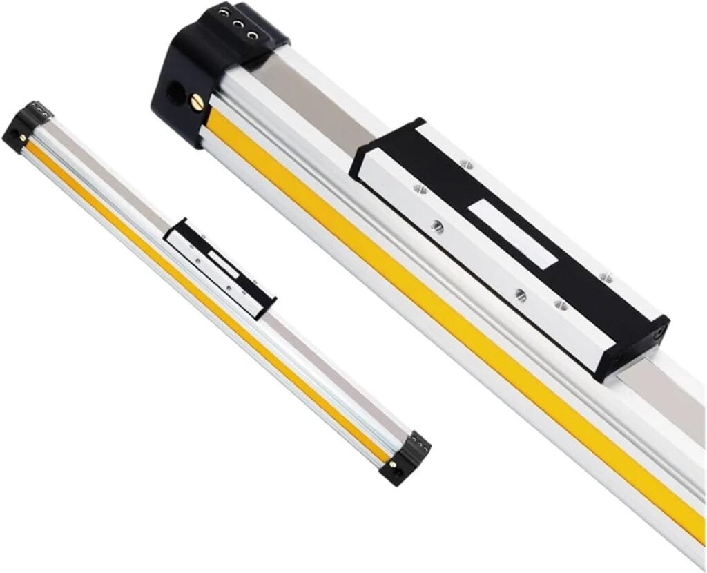
Yesterday, John from Michigan called frustrated because his new rodless air cylinder1 wasn’t generating enough force. After reviewing his calculations, we discovered he’d ignored back-pressure effects completely.
Table of Contents
- What Is the Basic Physics Behind Pressure Differential Force?
- How Do You Calculate Actual Force Output in Pneumatic Systems?
- What Factors Affect Pressure Differential Performance?
- How Does Pressure Differential Apply to Different Cylinder Types?
What Is the Basic Physics Behind Pressure Differential Force?
Pressure differential force follows fundamental fluid mechanics principles that govern all pneumatic system operations.
Pascal’s Law2 states that confined fluid pressure acts equally in all directions, creating force when pressure differences exist across surfaces with the formula F = ΔP × A.

Understanding Pascal’s Principle
Pascal’s principle explains how pressure creates mechanical advantage in pneumatic cylinders:
- Pressure acts perpendicular to all surfaces it contacts
- Force magnitude depends on pressure level and surface area
- Direction follows the path of least resistance
- Energy conservation governs overall system efficiency
The Force Equation Breakdown
The fundamental equation F = ΔP × A contains three critical variables:
| Variable | Definition | Units | Impact on Force |
|---|---|---|---|
| F | Generated Force | Pounds (lbf) or Newtons (N) | Direct output |
| ΔP | Pressure Differential | PSI or Bar | Linear multiplier |
| A | Effective Piston Area | Square inches or cm² | Linear multiplier |
Pressure vs. Force Relationship
Maria, a German automation engineer, initially confused pressure with force when sizing her pneumatic grippers. Pressure measures force per unit area, while force represents the total pushing or pulling capability. A small high-pressure system can generate the same force as a large low-pressure system.
Real-World Example
Consider a standard cylinder with 2-inch bore diameter:
- Effective area: π × (1)² = 3.14 square inches
- Supply pressure: 80 PSI
- Back pressure: 5 PSI
- Pressure differential: 75 PSI
- Generated force: 75 × 3.14 = 235.5 lbf
This calculation assumes perfect conditions without friction losses or dynamic effects.
How Do You Calculate Actual Force Output in Pneumatic Systems?
Theoretical calculations often overestimate actual force output due to real-world losses and dynamic effects.
Actual force equals theoretical force minus friction losses, back-pressure effects, and dynamic loading: F_actual = (ΔP × A) – F_friction – F_dynamic – F_backpressure.
Theoretical vs. Actual Force Calculations
Theoretical Force Calculation
Basic formula assumes ideal conditions:
- No friction losses
- Instantaneous pressure buildup
- Perfect sealing
- Uniform pressure distribution
Actual Force Considerations
Real pneumatic systems experience multiple force reductions:
| Loss Factor | Typical Reduction | Cause |
|---|---|---|
| Seal Friction | 5-15% | O-ring and wiper drag |
| Dynamic Loading | 10-25% | Acceleration forces |
| Back Pressure | 5-20% | Exhaust restrictions |
| Pressure Drop | 3-10% | Line losses and fittings |
Step-by-Step Calculation Process
Step 1: Calculate Theoretical Force
F_theoretical = Supply Pressure × Effective Area
Step 2: Account for Back Pressure
F_adjusted = (Supply Pressure – Back Pressure) × Effective Area
Step 3: Subtract Friction Losses
F_friction = F_adjusted × Friction Coefficient (typically 0.05-0.15)
Step 4: Consider Dynamic Effects
For moving loads, subtract acceleration forces:
F_dynamic = Mass × Acceleration
Practical Example: Rodless Cylinder Sizing
John’s Michigan application required 500 lbf output force:
- Target force: 500 lbf
- Supply pressure: 80 PSI
- Back pressure: 10 PSI (exhaust restrictions)
- Friction coefficient: 0.10
- Safety factor: 1.25
Calculation Process:
- Net pressure: 80 – 10 = 70 PSI
- Required area: 500 ÷ 70 = 7.14 sq in
- Friction adjustment: 7.14 ÷ 0.90 = 7.93 sq in
- Safety factor: 7.93 × 1.25 = 9.91 sq in
- Recommended bore: 3.5 inches (9.62 sq in effective area)
Our rodless pneumatic cylinder selection perfectly matched his requirements while providing adequate safety margin.
What Factors Affect Pressure Differential Performance?
Multiple system variables influence how effectively pressure differential converts to usable force output.
Temperature, air quality, system design, and component selection significantly impact pressure differential performance through effects on pressure losses, friction, and dynamic response.

Environmental Factors
Temperature Effects
Temperature changes affect pneumatic performance through:
- Pressure variations: 1 PSI change per 5°F temperature swing
- Seal hardness: Cold temperatures increase friction
- Air density: Hot air reduces effective pressure
- Condensation: Moisture creates pressure drops
Altitude Considerations
Higher altitudes reduce atmospheric pressure, affecting:
- Exhaust back-pressure: Lower atmospheric pressure improves performance
- Compressor efficiency: Reduced air density affects compression
- Seal performance: Pressure differentials change seal behavior
System Design Factors
Air Source Treatment Quality
Poor air quality reduces performance through:
| Contamination Type | Performance Impact | Solution |
|---|---|---|
| Particles | Increased friction and wear | Proper filtration |
| Moisture | Corrosion and freezing | Air dryers |
| Oil | Seal swelling and degradation | Oil removal filters |
Piping and Fitting Design
Pressure losses occur throughout the pneumatic system:
- Pipe diameter: Undersized pipes create restrictions
- Fitting selection: Sharp corners increase turbulence
- Line length: Longer runs increase pressure drop
- Elevation changes: Vertical runs affect pressure
Component Selection Impact
Valve Performance
Solenoid valve selection affects pressure differential through:
- Flow coefficient (Cv)3: Higher Cv reduces pressure drop
- Response time: Faster valves improve dynamic performance
- Port size: Larger ports minimize restrictions
Cylinder Design Variations
Different cylinder types exhibit varying pressure differential characteristics:
Standard Cylinder Performance:
- Simple piston design minimizes friction
- Single pressure chamber maximizes efficiency
- Predictable force calculations
Double Rod Cylinder Characteristics:
- Equal areas on both sides
- Consistent force in both directions
- Slightly higher friction due to dual seals
Rodless Cylinder Considerations:
- External guide systems add friction
- Magnetic coupling may introduce losses
- Higher precision requires tighter tolerances
Maria’s German facility improved their mini cylinder performance by 30% after upgrading to our high-flow pneumatic fittings and optimizing their air source treatment units.
How Does Pressure Differential Apply to Different Cylinder Types?
Each pneumatic cylinder type converts pressure differential to force through unique mechanical arrangements and design characteristics.
Standard cylinders offer maximum force efficiency, double rod cylinders provide equal bidirectional forces, while rodless cylinders sacrifice some efficiency for compact design and long stroke capabilities.
Standard Cylinder Force Characteristics
Extending Force Calculation
F_extend = P_supply × A_full – P_back × A_rod
Where:
- A_full = Full piston area
- A_rod = Rod cross-sectional area
- P_back = Back pressure in rod-side chamber
Retracting Force Calculation
F_retract = P_supply × (A_full – A_rod) – P_back × A_full
Standard cylinders typically generate 15-25% less retracting force due to reduced effective area.
Double Rod Cylinder Applications
Double rod cylinders provide unique advantages:
- Equal force: Same effective area both directions
- Symmetric mounting: Balanced mechanical loads
- Precise positioning: No force variation affects accuracy
Force Calculation
F_both_directions = P_supply × (A_full – 2 × A_rod)
The dual rods reduce effective area but ensure consistent performance.
Rodless Cylinder Force Considerations
Magnetic Coupling Systems
Magnetic rodless cylinders experience additional losses:
- Coupling efficiency: 85-95% force transmission
- Air gap effects: Larger gaps reduce efficiency
- Temperature sensitivity: Heat affects magnetic strength
Mechanical Coupling Systems
Mechanically coupled rodless cylinders offer:
- Higher efficiency: 95-98% force transmission
- Better accuracy: Direct mechanical connection
- Seal considerations: External seals add friction
Rotary Actuator Force Conversion
Rotary actuators convert linear pressure differential to rotational torque:
Torque Calculation:
T = F × Lever Arm = (ΔP × A) × R
Where R is the effective radius of the vane or rack system.
Pneumatic Gripper Force Applications
Pneumatic grippers multiply force through mechanical advantage:
| Gripper Type | Force Multiplication | Efficiency |
|---|---|---|
| Parallel | 1:1 ratio | 90-95% |
| Angular | 1.5-3:1 ratio | 85-90% |
| Toggle | 3-10:1 ratio | 80-85% |
Slide Cylinder Specialized Applications
Slide cylinders combine linear and rotary motion:
- Dual chambers: Independent pressure control
- Complex force vectors: Multi-directional capabilities
- Precision requirements: Tight tolerances affect friction
Application-Specific Recommendations
High-Force Applications
For maximum force output, choose:
- Large bore standard cylinders
- High supply pressure (100+ PSI)
- Minimal back-pressure restrictions
- Low-friction sealing systems
Precision Applications
For accurate positioning, select:
- Rodless cylinders with mechanical coupling
- Consistent air source treatment units
- Proper manual valve flow control
- Feedback positioning systems
John’s Michigan facility achieved 40% better performance after switching from magnetic to mechanical coupling in their rodless air cylinder application, demonstrating how component selection impacts pressure differential effectiveness.
Conclusion
Pressure differential creates force through Pascal’s principle, but real-world applications require careful consideration of losses, system design, and component selection for optimal performance.
FAQs About Pressure Differential Force Physics
Q: What is the basic formula for pneumatic force?
Force equals pressure differential times effective piston area (F = ΔP × A). This fundamental relationship governs all pneumatic force calculations in cylinder applications.
Q: Why is actual force less than theoretical force?
Real systems experience friction losses, back-pressure effects, dynamic loading, and pressure drops that reduce actual force output by 20-40% compared to theoretical calculations.
Q: How does temperature affect pressure differential force?
Temperature changes affect air pressure at roughly 1 PSI per 5°F, while also influencing seal friction and air density, impacting overall force output.
Q: What’s the difference between pressure and force?
Pressure measures force per unit area (PSI or Bar), while force represents total pushing/pulling capability (pounds or Newtons). Larger areas convert pressure to higher forces.
Q: Do rodless cylinders generate less force than standard cylinders?
Rodless cylinders typically generate 5-15% less force due to coupling losses and external sealing friction, but offer advantages in stroke length and mounting flexibility.
-
Discover the design, types, and operational advantages of rodless air cylinders in industrial automation. ↩
-
Explore Pascal’s Law, a fundamental principle of fluid mechanics that explains how pressure is transmitted in a confined fluid. ↩
-
Learn about the flow coefficient (C_v), a key metric used to compare the flow capacity of valves and other pneumatic components. ↩
