

Ever wondered why some pneumatic cylinders develop mysterious leakage issues that seem to appear overnight? The answer might lie in a phenomenon borrowed from automotive safety – hydroplaning. Just as your car tires can lose contact with wet roads, cylinder seals can “hydroplane” on excessive lubricant films, leading to catastrophic sealing failure. In my 15 years troubleshooting pneumatic systems, I’ve seen this overlooked issue cost companies millions in unplanned downtime.
Hydrodynamic lubrication occurs when fluid pressure creates a lubricant film thick enough to separate seal surfaces from cylinder walls, causing seals to “hydroplane” and lose sealing effectiveness, typically at velocities above 0.5 m/s with excessive lubrication. Understanding this balance is crucial for maintaining optimal cylinder performance.
Just three months ago, I received an urgent call from David, a plant engineer at a food processing facility in Wisconsin. His high-speed packaging line cylinders were experiencing sudden, inexplicable air leakage that traditional troubleshooting couldn’t resolve. The frustration in his voice was evident – production was down 40% and customer orders were backing up. 😟
Table of Contents
- What Is Hydrodynamic Lubrication in Pneumatic Cylinders?
- When Do Cylinder Seals Begin to Hydroplane?
- How Can You Detect and Prevent Seal Hydroplaning?
- Which Lubrication Strategies Optimize Seal Performance?
What Is Hydrodynamic Lubrication in Pneumatic Cylinders?
Understanding hydrodynamic lubrication is essential for predicting and preventing seal performance issues.
Hydrodynamic lubrication occurs when relative motion1 between surfaces generates sufficient fluid pressure to create a continuous lubricant film that completely separates contacting surfaces, transitioning from boundary lubrication to full fluid film lubrication. This transition fundamentally changes seal behavior and effectiveness.
The Physics of Hydrodynamic Lubrication
The Reynolds equation governs hydrodynamic pressure generation:
Where:
- ( ) = film thickness
- ( ) = pressure
- ( ) = dynamic viscosity2
- ( ) = surface velocity
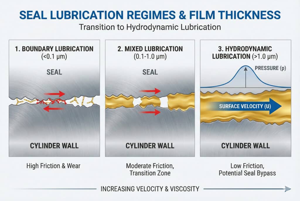
Lubrication Regimes in Cylinders
Boundary Lubrication
- Film thickness: < 0.1 μm
- Direct surface contact occurs
- High friction and wear
- Typical at low speeds
Mixed Lubrication
- Film thickness: 0.1-1.0 μm
- Partial surface separation
- Moderate friction
- Transition zone behavior
Hydrodynamic Lubrication
- Film thickness: > 1.0 μm
- Complete surface separation
- Low friction but potential seal bypass
- High-speed operation characteristic
Critical Parameters Affecting Film Formation
| Parameter | Impact on Film Thickness | Optimal Range |
|---|---|---|
| Velocity | Directly proportional | 0.1-0.8 m/s |
| Viscosity | Increases film thickness | 10-50 cSt |
| Load | Inversely proportional | Design dependent |
| Surface roughness | Affects film stability | Ra 0.1-0.4 μm |
The challenge is maintaining sufficient lubrication for seal protection while preventing excessive film buildup that causes hydroplaning. 🎯
When Do Cylinder Seals Begin to Hydroplane?
Predicting the onset of seal hydroplaning requires understanding multiple interacting factors.
Seal hydroplaning typically begins when lubricant film thickness exceeds 2-3 times the seal’s designed interference fit3, usually occurring at velocities above 0.5 m/s with viscosities over 32 cSt and excessive lubrication rates. The exact threshold depends on seal geometry, material properties, and operating conditions.
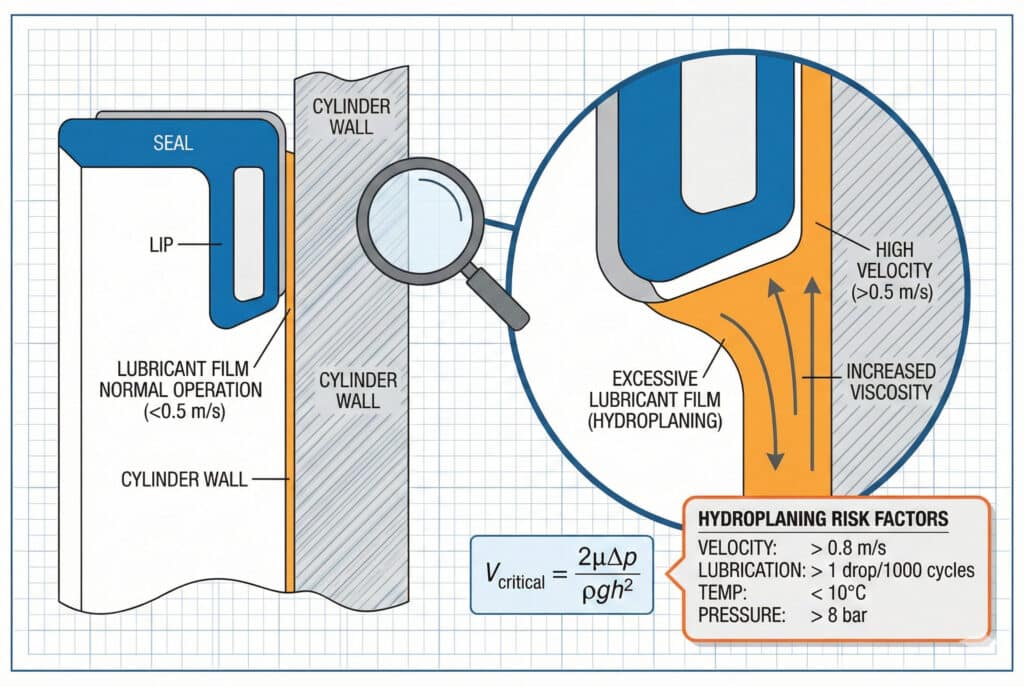
Critical Velocity Calculations
The critical velocity for hydroplaning can be estimated using:
Where:
- ( ) = lubricant viscosity
- ( ) = pressure differential
- () = lubricant density
- ( ) = gap height
- ( ) = film thickness
Hydroplaning Risk Factors
High-Risk Conditions
- Velocity: > 0.8 m/s sustained operation
- Lubrication rate: > 1 drop per 1000 cycles
- Temperature: < 10°C (increased viscosity)
- Pressure: > 8 bar differential
Seal Design Factors
- Interference fit: Low interference increases risk
- Lip geometry: Sharp lips more prone to lifting
- Material hardness: Soft seals deform more easily
- Surface finish: Very smooth surfaces promote film formation
Application-Specific Thresholds
| Application Type | Critical Velocity | Risk Level | Mitigation Strategy |
|---|---|---|---|
| Standard Industrial | 0.6 m/s | Low | Standard lubrication |
| High-Speed Packaging | 1.2 m/s | High | Controlled lubrication |
| Precision Positioning | 0.3 m/s | Medium | Optimized seal selection |
| Heavy Duty | 0.8 m/s | Medium | Enhanced seal design |
Environmental Influences
Temperature significantly affects hydroplaning risk:
- Cold conditions increase viscosity, promoting thicker films
- Hot conditions reduce viscosity but may cause seal degradation
- Humidity can affect lubricant properties and seal swelling
Remember David from Wisconsin? His packaging line operated at 1.4 m/s with automatic lubrication set too high. The combination created perfect hydroplaning conditions. After we optimized his lubrication schedule and upgraded to our Bepto low-friction seals, his leakage issues disappeared completely! 🚀
How Can You Detect and Prevent Seal Hydroplaning?
Early detection and prevention of hydroplaning saves costly downtime and component replacement.
Hydroplaning detection involves monitoring air consumption increases, velocity-dependent leakage patterns, and lubricant film thickness measurements, while prevention focuses on optimized lubrication rates, seal selection, and operating parameter control. Proactive monitoring is far more cost-effective than reactive repairs.
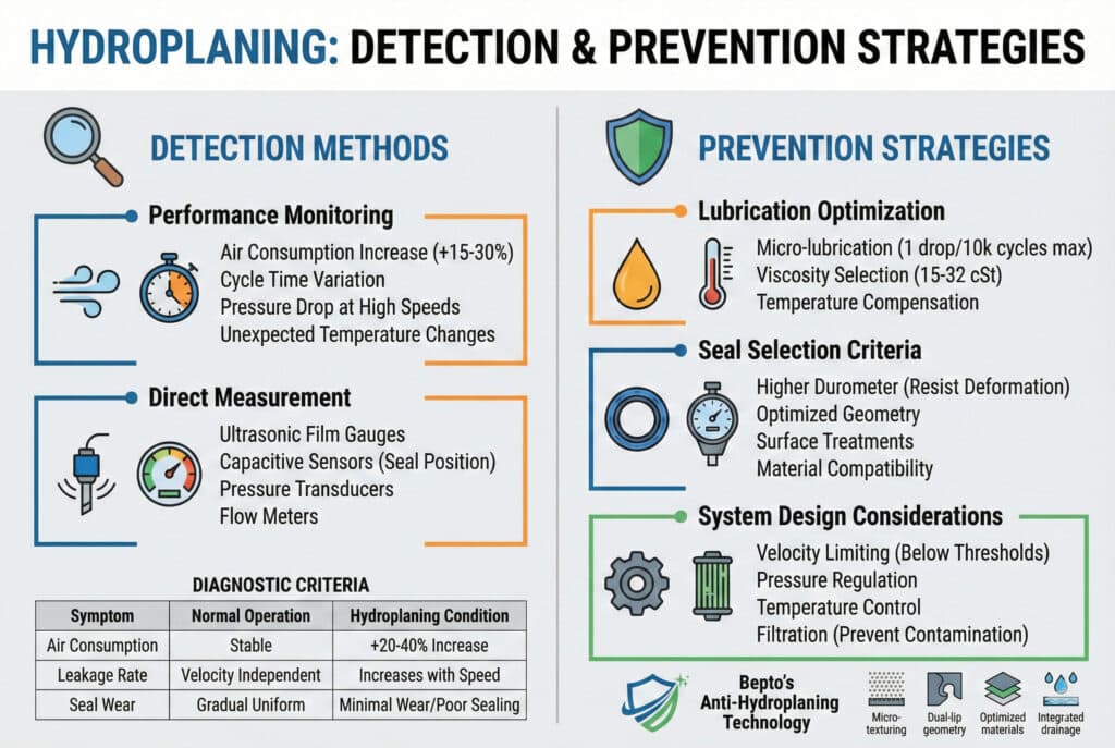
Detection Methods
Performance Monitoring
- Air consumption: 15-30% increase indicates potential hydroplaning
- Cycle time variation: Inconsistent performance suggests film instability
- Pressure drop: Reduced holding pressure at high speeds
- Temperature monitoring: Unexpected temperature changes
Direct Measurement Techniques
- Ultrasonic thickness gauges: Measure lubricant film directly
- Capacitive sensors: Detect seal position changes
- Pressure transducers: Monitor dynamic pressure variations
- Flow meters: Track air consumption patterns
Diagnostic Criteria
| Symptom | Normal Operation | Hydroplaning Condition |
|---|---|---|
| Air consumption | Stable | +20-40% increase |
| Leakage rate | Velocity independent | Increases with speed |
| Seal wear | Gradual, uniform | Minimal wear, poor sealing |
| Performance | Consistent | Speed-dependent degradation |
Prevention Strategies
Lubrication Optimization
- Micro-lubrication: 1 drop per 10,000 cycles maximum
- Viscosity selection: 15-32 cSt for most applications
- Temperature compensation: Adjust rates for ambient conditions
- Quality control: Use clean, specified lubricants only
Seal Selection Criteria
- Higher durometer4: Resist deformation under film pressure
- Optimized geometry: Designed for specific velocity ranges
- Surface treatments: Anti-hydroplaning coatings available
- Material compatibility: Match seal to lubricant chemistry
System Design Considerations
- Velocity limiting: Keep speeds below critical thresholds
- Pressure regulation: Maintain consistent operating pressures
- Temperature control: Stabilize operating environment
- Filtration: Prevent contamination that affects film formation
Bepto’s Anti-Hydroplaning Technology
Our advanced seal designs incorporate:
- Micro-texturing: Surface patterns that break up lubricant films
- Dual-lip geometry: Primary sealing with secondary film control
- Optimized materials: Formulated for specific velocity ranges
- Integrated drainage: Channels that manage excess lubricant
Which Lubrication Strategies Optimize Seal Performance?
Proper lubrication strategy balances seal protection with hydroplaning prevention.
Optimal lubrication strategies employ controlled micro-dosing, viscosity-matched lubricants, and velocity-dependent application rates to maintain the mixed lubrication regime that provides seal protection without hydroplaning risk. The key is precision control rather than excessive application.
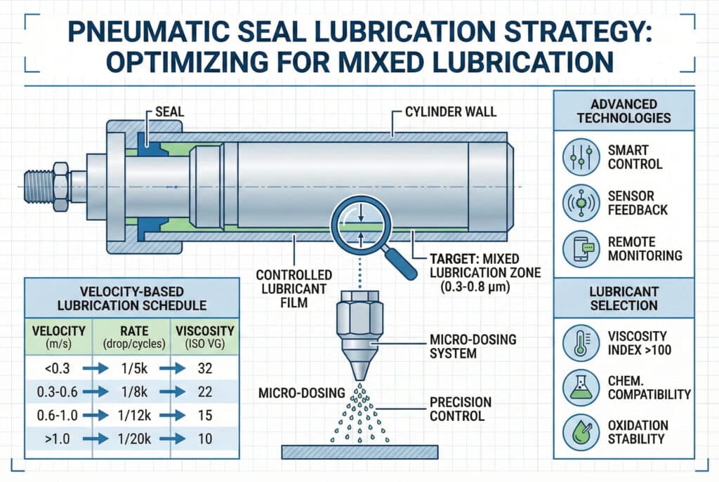
Lubrication Regime Optimization
Target: Mixed Lubrication Zone
- Film thickness: 0.3-0.8 μm
- Friction coefficient: 0.05-0.15
- Wear rate: Minimal
- Sealing effectiveness: Maximum
Application Rate Guidelines
Velocity-Based Lubrication Schedule
| Operating Velocity | Lubrication Rate | Viscosity Grade | Application Method |
|---|---|---|---|
| < 0.3 m/s | 1 drop/5,000 cycles | ISO VG 32 | Manual/timer |
| 0.3-0.6 m/s | 1 drop/8,000 cycles | ISO VG 22 | Automatic dosing |
| 0.6-1.0 m/s | 1 drop/12,000 cycles | ISO VG 15 | Precision micro-dosing |
| > 1.0 m/s | 1 drop/20,000 cycles | ISO VG 10 | Electronic control |
Advanced Lubrication Technologies
Micro-Dosing Systems
- Precision: ±2% volume accuracy
- Timing: Synchronized with cylinder position
- Monitoring: Real-time consumption tracking
- Adjustment: Automatic rate optimization
Smart Lubrication Control
- Sensor feedback: Temperature and humidity compensation
- Predictive algorithms: Anticipate lubrication needs
- Remote monitoring: Track performance metrics
- Maintenance alerts: Proactive system notifications
Lubricant Selection Criteria
Physical Properties
- viscosity index5: > 100 for temperature stability
- Pour point: -30°C minimum for cold operation
- Flash point: > 200°C for safety
- Oxidation stability: Extended service life
Chemical Compatibility
- Seal materials: Must not cause swelling or degradation
- Metal components: Corrosion protection required
- Environmental: Food-grade or environmentally safe as needed
Mastering hydrodynamic lubrication principles ensures your pneumatic systems operate at peak efficiency while avoiding the costly pitfalls of seal hydroplaning. 💪
FAQs About Hydrodynamic Lubrication and Seal Hydroplaning
How can I tell if my cylinder seals are hydroplaning?
Look for velocity-dependent air leakage, increased air consumption at higher speeds, and seals that show minimal wear despite poor sealing performance. Hydroplaning seals often appear in good condition because they’re not making proper contact with cylinder walls.
What’s the difference between over-lubrication and hydroplaning?
Over-lubrication refers to excessive lubricant application, while hydroplaning is the specific condition where lubricant film pressure lifts seals away from sealing surfaces. Over-lubrication can lead to hydroplaning, but hydroplaning can occur even with proper lubrication rates under certain conditions.
Can hydroplaning damage my cylinder seals permanently?
Hydroplaning itself rarely damages seals physically, but the resulting poor sealing allows contamination entry and pressure fluctuations that can cause rapid seal degradation. The real damage comes from secondary effects rather than the hydroplaning phenomenon itself.
At what cylinder speed should I be concerned about hydroplaning?
Hydroplaning risk increases significantly above 0.5 m/s, with critical concern levels starting around 0.8-1.0 m/s depending on lubrication and seal design. High-speed applications above 1.2 m/s require specialized anti-hydroplaning seal technologies.
How do I calculate the optimal lubrication rate for my application?
Start with 1 drop per 10,000 cycles as a baseline, then adjust based on operating velocity, temperature, and observed performance, reducing rates for higher speeds to prevent hydroplaning. Monitor air consumption and leakage rates to fine-tune the optimal balance for your specific application.
-
Gain insights into how relative motion between surfaces generates the pressure required for fluid film separation. ↩
-
Explore the fundamental role of dynamic viscosity in determining the thickness and stability of lubricant films. ↩
-
Understand the engineering principles of interference fits and their impact on seal bypass and leakage. ↩
-
Learn how the durometer of a seal material influences its resistance to deformation under high fluid pressure. ↩
-
Discover why the viscosity index is a critical factor for maintaining lubricant effectiveness across varying temperatures. ↩
