

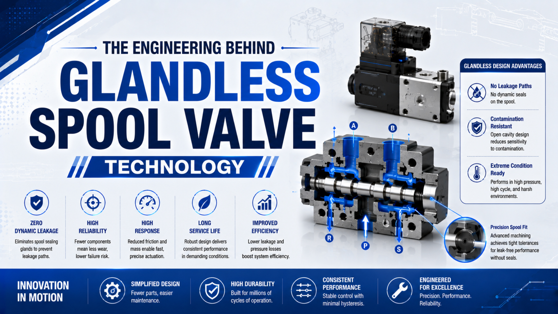
A glandless pneumatic spool valve uses a closely matched spool and sleeve instead of soft dynamic seals on the moving spool lands.
As the spool shifts, its lands uncover and cover supply, work, and exhaust passages. This controlled running fit limits bypass while avoiding the sliding drag and wear mechanism of an elastomer-sealed spool.
That definition changes the selection conversation.
“Glandless” does not mean the entire valve contains no seals, produces zero internal leakage, or handles corrosive process gases. It also doesn’t identify magnetic coupling, a bellows, or a diaphragm valve. Those are separate constructions. For machine-air service, selection still comes down to circuit function, permitted leakage, flow, pilot conditions, air quality, and the exact catalog model.
Key Takeaways
- Norgren lists 900 L/min for its V44 glandless 5/2 valve and 1,200 L/min for the V45 soft-seal version.
- Glandless removes soft dynamic spool seals, not all static or pilot seals.
- Specify function, pilot pressure, air quality, flow, and permitted leakage by part number.
What Does “Glandless” Mean in a Pneumatic Spool Valve?
Norgren identifies the V44 as a glandless spool valve and the V45 as a soft-seal spool valve in the same 26 mm ISO family (IMI Norgren V44/V45 datasheet, 2024). In this context, glandless describes the moving spool-and-sleeve sealing architecture, not a universally hermetic valve body.
A glandless spool valve is a directional valve whose spool uses a controlled running fit inside a matched sleeve instead of soft dynamic seals on its lands. Axial spool position determines which ports communicate. A 5/2 valve alternately sends supply air to one work port while connecting the other work port to exhaust. The spool-versus-poppet guide explains that element-level distinction in more detail. In a glandless design, the spool and sleeve form a matched sliding pair. Elastomeric rings do not rub against the bore. A soft-seal spool valve is a different construction that uses seals such as HNBR on the moving element. That difference changes friction and leakage behavior. It also affects contamination sensitivity and port geometry, but it doesn’t decide the complete valve’s performance by itself.
Static seals may still sit at valve-body joints. Other locations include end covers, the pilot section, and the sub-base. Norgren’s glandless ISO STAR data lists a hard-anodized PTFE-coated spool-and-sleeve pair together with NBR seals elsewhere in the assembly (IMI Norgren ISO STAR ATEX datasheet). Therefore “glandless” should never be translated into “seal-free.”
Pilot actuation is the separate force-amplifying stage that shifts the main valve element. Movement can come from a solenoid pilot or air pilot. Diaphragms, springs, and electronic pressure-control stages are other possible operators. Norgren’s VP50 manual explicitly calls its pneumatic section a “diaphragm actuated glandless spool valve”: pilot pressure acts on a diaphragm, and the diaphragm moves the spool (IMI Norgren VP50 manual). Diaphragm motion is the actuator mechanism, not an alternative definition of glandless sealing.
Catalog reading becomes safer when you separate three questions: what element routes the main flow, how that moving element seals, and what force shifts it. “Spool,” “glandless,” and “solenoid pilot actuated” answer those questions in that order.
The Matched Spool-and-Sleeve Mechanism
In the 2024 V44/V45 catalog, the glandless V44 uses a hard-anodized, coated, matched-aluminium spool and sleeve, while the V45 uses an aluminium-alloy spool with HNBR seals (IMI Norgren). “Matched” is the engineering clue: the sliding pair is controlled as an assembly rather than treated as two generic interchangeable parts.
Geometry controls every switching transition.
When pilot force shifts the spool, each land moves relative to ports cut through the sleeve. Land width, groove geometry, overlap, stroke, and sleeve windows determine the connection sequence. A positive overlap can briefly block paths during transition. An underlap can briefly connect them. That timing affects pressure crossover and exhaust behavior even when the steady-state symbols look identical. Closed-loop proportional valves add another layer, explained in the spool-position feedback guide. Surface treatment serves several jobs. Hard anodizing increases the aluminium surface’s wear resistance. Low-friction coating reduces sliding resistance and helps the pair operate with lubricated or non-lubricated compressed air when the manufacturer permits it. Coating condition, roundness, straightness, surface finish, and thermal growth all influence whether the spool moves freely without opening an excessive leakage path.
Why use a separate sleeve rather than machine every flow edge directly into the body? By creating the bore, port windows, coating, and matched fit as one controlled subassembly, the manufacturer can inspect the critical geometry while separating the precision switching surface from the die-cast body. Don’t mix parts casually. If the supplier describes the parts as matched, preserve their pairing during inspection and service. Replacing only one member can change the running fit, while polishing a spool or enlarging a bore can permanently alter both leakage and freedom of movement.
How Does Clearance Balance Leakage and Friction?
Clippard distinguishes lapped or shear-design spools from dynamic-seal and O-ring spools, noting that lapped designs can run without lubrication but may have higher leak rates and need better-conditioned air (Clippard pneumatic valve technical guide). The clearance is therefore a controlled compromise, not a claim of contactless, zero-leak sealing.
A controlled gap does two jobs at once.
A metal spool must move without binding through its full temperature and pressure range. That requires a running gap. Air can migrate across the gap from a higher-pressure region to a lower-pressure region, so some internal bypass may be intrinsic to the design. Actual bypass depends on geometry, pressure differential, temperature, manufacturing condition, wear, and the supplier’s test method. Smaller clearance can reduce bypass, yet it narrows the tolerance for particles, deposits, thermal expansion, coating variation, and misalignment. Larger clearance can move more freely but increases the potential flow between lands. Engineering should target repeatable shifting and acceptable leakage across the rated operating envelope, not “the smallest possible gap.”
This distinction also prevents a common diagnostic mistake. External leakage at a sub-base joint, pilot exhaust, connector, or damaged static seal is not proof that the glandless spool fit failed. Conversely, no audible external leak does not prove that internal bypass is within specification. The internal-leakage troubleshooting guide shows why symptom location and valve construction must be separated before assigning a cause.
Pressure-decay testing of an assembled circuit measures every enclosed leak path together. To judge the main spool, isolate the correct ports and reproduce the manufacturer’s valve state and flow direction before matching pressure, temperature, and acceptance limit to the cited test. Without that isolation, tubing and cylinder seals contribute to the result. Fittings and pilot passages can do the same. One number then hides several leak paths.
What Do Glandless and Soft-Seal Catalog Data Actually Show?
For one directly comparable family, Norgren lists 5/2 nominal flow of 900 L/min, Cv 0.92, for the V44 glandless valve and 1,200 L/min, Cv 1.22, for the V45 soft-seal valve (IMI Norgren V44/V45 datasheet, 2024). Those values show a product-level tradeoff, not a universal ranking of all designs.
| Norgren family and function | Glandless spool | Soft-seal spool | What the comparison proves |
|---|---|---|---|
| V44/V45 5/2 | 900 L/min, Cv 0.92 | 1,200 L/min, Cv 1.22 | The soft-seal version has the higher listed flow in this family |
| V44/V45 5/3 | 900 L/min, Cv 0.92 | 1,150 L/min, Cv 1.17 | Function changes the soft-seal value |
| VS45 5/2 | 3,200 L/min, Cv 3.2 | 4,200 L/min, Cv 4.2 | The same family-level pattern appears at a larger valve-island size |
| VS45 5/3 | 2,900 L/min, Cv 2.9 | 3,700 L/min, Cv 3.7 | Center function and internal path still matter |
Read this comparison narrowly, not categorically.
For VS45, the catalog describes glandless spool and sleeve for long life and soft-seal spool for high flow (IMI Norgren VS45 datasheet). It does not say that every glandless valve lasts a fixed number of years or that every soft-seal valve fails early. Duty cycle, air condition, switching pressure, temperature, and maintenance determine the realized service interval. Flow numbers also need context. Compare the same valve function, flow direction, pressure conditions, unit convention, and test basis. A 5/3 center configuration may not match a 5/2 value in the same body. Restrictions may instead come from the manifold, fitting, tube, silencer, or actuator. For broader comparison methods, use the pneumatic valve flow-sizing guide.
Pressure capability can vary inside one series. VS45 glandless solenoid-pilot models with internal pilot supply are rated to 10 bar maximum, while specified external-pilot glandless models reach 16 bar; the soft-seal versions remain at 10 bar in that catalog. This is a pilot-and-model result, not evidence that glandless construction inherently creates a 16 bar valve. Avoid purchasing from the words “long life” alone. Ask for the exact leakage specification and flow path. Record operating and pilot-pressure windows plus the switching test and temperature range. Add the approved medium, air quality, expected duty, and endurance evidence for the offered part number.
Which Air-Quality and Pilot Conditions Matter?
Both the V44/V45 and VS45 catalogs specify compressed air filtered to 40 µm and permit lubricated or non-lubricated service. They also require air dry enough to prevent ice below +2°C (IMI Norgren V44/V45; IMI Norgren VS45). Permission for non-lubricated air does not waive filtration or drainage. Dryness and installation cleanliness still apply.
Clean air is part of the mechanism.
Tight sliding fits can be affected by particles and sticky compressor by-products; degraded lubricant, pipe scale, water, or assembly debris also matter. Clippard specifically cautions that lapped spool designs are less tolerant of variation in lubrication and compressor by-products. A finer filter isn’t automatically the answer. Start by confirming the stated requirement and filter efficiency, then review corrected flow, pressure drop, drainage, and contamination generated downstream.
See the unlubricated-air and spool-seal guide for the separate lubrication question. If a valve sticks, confirm the command signal and supply pressure first. Then check pilot pressure, pilot exhaust, manual override, coil voltage, and the correct sub-base. Only after those checks should you inspect contamination evidence. The valve contamination failure-analysis guide provides a structured way to distinguish particle damage from electrical, pressure, lubrication, and assembly faults.
Pilot supply deserves equal attention. An internally piloted valve uses main supply air to generate shifting force, so it may stop switching when inlet pressure falls below the model’s minimum. External pilot supply can let the main ports operate at low or even negative gauge pressure on specified models, but the pilot circuit still needs clean air within its own pressure range. Operator technology doesn’t redefine the main spool. A voice-coil pilot, solenoid pilot, or pneumatic diaphragm may create the force. Read the pilot-operated valve guide alongside the exact manual when diagnosing slow or incomplete shifting.
A Selection and Commissioning Checklist
ISO 15407-1 standardizes mounting interfaces for five-port directional valves in 18 mm and 26 mm sizes, and ISO confirmed the 2000 edition as current in 2022 (ISO 15407-1). Interface compatibility helps replacement planning, but it does not make two valves equal in spool construction, flow, pilot scheme, leakage, wiring, or center function.
Use this sequence before approving a valve:
- Define every circuit state. Choose 5/2 or 5/3, then document normal state, center condition, return method, reverse flow, and vacuum duty.
- Set measurable limits. Write acceptance values for internal leakage and external leakage. Add required flow, maximum pressure drop, response time, cycle rate, temperature range, and the evidence expected for service life.
- Check the pilot arrangement. Record internal or external supply and minimum pilot pressure. Then confirm exhaust routing, coil voltage, manual override, electrical duty, and fail position.
- Verify air and materials. Match the approved medium to filtration and dryness. Review lubrication policy, coating, static-seal materials, ambient exposure, and temperature limits. Standard compressed-air approval is not chemical-gas approval.
- Trace the installed flow path. Include sub-base galleries, fittings, tubing, silencers, regulators, and exhaust restrictions.
- Confirm interface details. Check the base pattern and port map first. Then verify the electrical connector, valve-island protocol, width, pressure-zone accessories, and replacement procedure.
Commissioning should create a baseline, not just prove that the actuator moves once. Verify port mapping and electrical command, cycle the valve at minimum and normal pressure, record supply and pilot pressure while shifting, inspect exhaust behavior, and measure leakage under the agreed states. Log voltage and temperature. Add air condition and cycle timing so future troubleshooting has a comparison. If the machine depends on a held pressure for safety, don’t treat a directional spool valve as the sole isolation device without a documented risk assessment. Internal bypass and loss of supply can affect the safe state. So can pilot behavior, stored energy, and actuator leakage. Use components and architecture rated for the required safety function.
When Should You Choose Glandless Instead of Soft-Seal?
Norgren positions the glandless V44 for long life and the soft-seal V45 for high flow; their 5/2 versions are listed at 900 L/min and 1200 L/min (IMI Norgren V44/V45 datasheet, 2024). Choose between them by the application’s measured priorities, not by assuming one construction is categorically superior.
Start with the failure consequence.
A glandless matched spool-and-sleeve valve is a strong candidate when the approved model meets your internal-leakage limit. It can suit projects that value low sliding-seal friction and non-lubricated-air permission alongside repeatable multiport routing and supplier endurance evidence. Correct filtration and dry air remain part of that decision. A soft-seal spool may be better when the related model provides materially higher flow. It may also offer the required function or leakage characteristic. Soft seals add contact and material-compatibility considerations, but that doesn’t make them an inferior design. They solve a different set of constraints.
Choose another valve architecture when the main requirement is verified tight shutoff or isolation of hazardous media. Sanitary construction, aggressive chemical compatibility, and certified safety functions also belong in a different selection process. A pneumatic glandless directional valve approved for filtered compressed air shouldn’t be promoted into process-gas service because its moving spool lacks elastomeric rings. Put the final choice on a one-page comparison sheet. Identify the part number, symbol, spool construction, rated medium, and flow first. Then add operating pressure, pilot pressure, leakage, temperature, filtration, materials, electrical interface, manifold fit, and acceptance test. That turns a vague technology preference into a traceable engineering decision.
Glandless Spool Valve FAQs
Norgren’s V44 catalog describes a matched and coated glandless spool-and-sleeve assembly. Its HNBR-sealed V45 counterpart still uses NBR static seals elsewhere in the valve (IMI Norgren V44/V45 datasheet, 2024). The five questions below address specification errors that most often distort selection and maintenance decisions.
Does glandless mean the valve contains no seals?
No. It means the moving main spool uses a matched spool-and-sleeve running fit rather than soft dynamic seals on its lands. The complete valve can still contain static body and sub-base seals. Pilot seals or a diaphragm operator may also be present. Norgren’s glandless ISO STAR catalog separately lists NBR seals.
Is a glandless spool valve a zero-leak valve?
No. Running clearance can permit internal bypass, and static joints or pilot components can create separate external leak paths. Obtain the model’s leakage limit and test conditions for each required state. Clippard notes that lapped spool valves can have higher leakage, which may rule them out for limited gas supplies or non-air media.
Is glandless spool technology always the higher-flow option?
No. Norgren lists 900 L/min for the glandless V44 5/2 model and 1200 L/min for its soft-seal V45 counterpart. The VS45 family lists 3200 L/min and 4200 L/min in the same order. These are family-specific examples. Compare function and pressure conditions together with the actual flow path and manifold.
Can I use a glandless pneumatic valve with chemical or sterile gases?
Only when the manufacturer approves the exact medium and service. Filtered compressed-air approval does not establish chemical compatibility or external containment; it says nothing about cleanliness or sanitary design. Before considering non-air service, review wetted materials and coatings together with static seals, lubricant, pilot exhaust, leakage rating, certification, and cleaning requirements.
Can the spool and sleeve be replaced separately?
Don’t assume so. When a catalog calls the aluminium spool and sleeve “matched,” their running fit is an assembly characteristic. Mixing used and new parts can alter leakage or freedom of movement. Field polishing and bore modification create the same risk. Follow the model’s repair instructions and replace the matched assembly or complete valve when specified.
Sources and technical references
IMI Norgren’s V44/V45 Mini ISO valve datasheet provides the 2024 technical data and material list. It also supplies functions and pressure ranges alongside the glandless-versus-soft-seal flow comparison, while the VS45 valve-island datasheet provides corresponding values for the larger family.
The ISO STAR ATEX datasheet identifies spool-and-sleeve materials and NBR seals. The VP50 IO-Link operating manual documents its diaphragm-actuated glandless spool arrangement.
Clippard’s pneumatic valve technical guide distinguishes lapped, dynamic-seal, and O-ring spools. ISO 15407-1:2000 defines five-port directional-valve mounting interfaces and was confirmed current in 2022.