

Innledning
Is your high-speed automation line missing target positions and wasting precious cycle time? 🎯 When pneumatic slides overshoot their intended positions or take too long to settle, production throughput suffers, positioning accuracy deteriorates, and mechanical wear accelerates. These dynamic performance issues plague countless manufacturing operations daily.
Overshoot in pneumatic slides occurs when the carriage travels beyond its target position before settling, while settling time measures how long the system takes to reach and maintain stable positioning within acceptable tolerance. Typical high-speed stangløs sylinder1 systems experience 5-15mm overshoot and 50-200ms settling times, but proper cushioning, pressure optimization, and control strategies can reduce these by 60-80%.
Just last quarter, I worked with Marcus, a senior automation engineer at a semiconductor packaging facility in Austin, Texas. His pick-and-place system was experiencing 12mm overshoot at the end of each 800mm stroke, causing positioning errors that slowed his cycle time by 0.3 seconds per part. After we analyzed his Bepto rodless cylinder configuration and optimized the cushioning parameters, overshoot dropped to 3mm and settling time improved by 65%. Let me share the analytical approach that delivered these results. 📊
Innholdsfortegnelse
- What Causes Overshoot and Extended Settling Time in Pneumatic Slides?
- How Do You Measure and Quantify Dynamic Performance Metrics?
- What Engineering Solutions Reduce Overshoot and Improve Settling Time?
- How Does Load Mass and Velocity Affect System Dynamics?
What Causes Overshoot and Extended Settling Time in Pneumatic Slides?
Understanding the root causes of dynamic performance issues is the first step toward optimization. 🔍
Overshoot and poor settling time result from four primary factors: excessive kinetic energy at end-of-stroke that overwhelms cushioning capacity, inadequate pneumatic cushioning or mechanical shock absorbers, compressible air acting as a spring that creates oscillation, and insufficient damping2 in the system to dissipate energy quickly. The interplay between moving mass, velocity, and deceleration distance determines final performance.
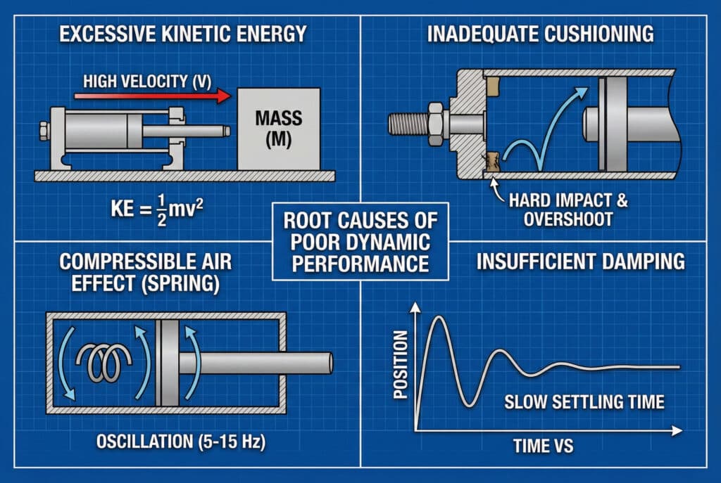
The Physics of Pneumatic Deceleration
When a high-speed pneumatic slide approaches its end position, kinetic energy must be absorbed and dissipated. The energy equation tells us:
$$
Kinetic\ Energy
= \frac{1}{2} \times Mass \times Velocity^{2}
$$
This energy must be absorbed within the available deceleration distance. Problems arise when:
- Velocity is too high: Energy increases with the square of speed
- Mass is excessive: Heavier loads carry more momentum
- Cushioning is inadequate: Insufficient absorption capacity
- Damping is poor: Energy converts to oscillation rather than heat
Common System Deficiencies
| Utgave | Symptom | Typisk årsak |
|---|---|---|
| Hard Impact | Loud bang, no overshoot | No cushioning engaged |
| Excessive Overshoot | >10mm past target | Cushioning too soft or worn |
| Oscillasjon | Multiple bounces | Insufficient damping |
| Slow Settling | >200ms stabilization | Over-damped or low pressure |
At Bepto, we’ve analyzed hundreds of high-speed rodless cylinder applications. The most common issue? Engineers select cushioning based on catalog recommendations without accounting for their specific velocity and load conditions.
Effekter av luftkompressibilitet
Unlike hydraulic systems, pneumatic systems must contend with air’s compressibility. As the cushion engages, compressed air acts as a spring, storing energy that can cause rebound. The pressure-volume relationship creates natural oscillation frequencies typically between 5-15 Hz in rodless cylinder systems.
How Do You Measure and Quantify Dynamic Performance Metrics?
Accurate measurement is essential for systematic improvement and validation. 📏
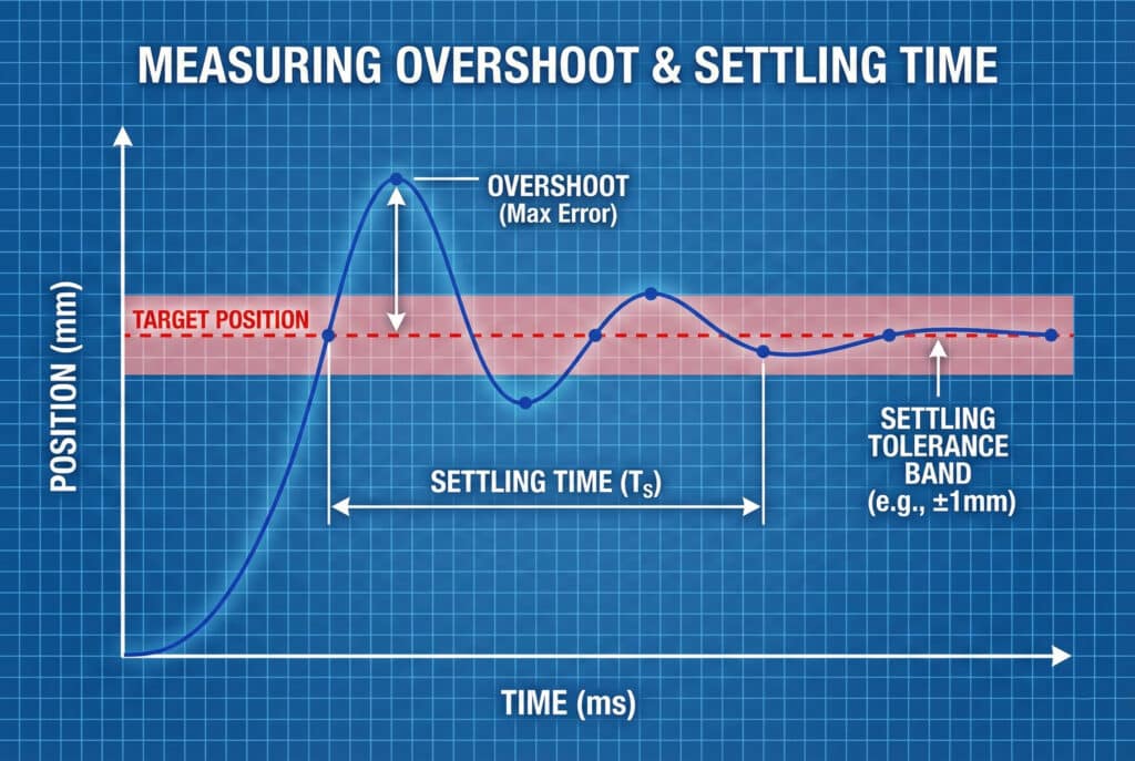
To properly measure overshoot and settling time, you need: a high-resolution position sensor (minimum 0.1mm resolution), data acquisition at 1kHz or higher sampling rate, clear definition of settling tolerance (typically ±0.5mm to ±2mm), and multiple test runs under consistent conditions. Overshoot is measured as maximum position error beyond target, while settling time is when the system enters and remains within tolerance band.
Måleutstyr og oppsett
Essential Instrumentation
- Lineære enkodere3: Magnetic or optical, 0.01-0.1mm resolution
- Laser displacement sensors: Non-contact, microsecond response time
- Draw-wire sensors: Cost-effective for longer strokes
- Datafangstsystem: PLC high-speed counters or dedicated DAQ
Nøkkelindikatorer for ytelse
Overshoot (OS): Maximum position beyond target
- Formula: OS = (Peak Position – Target Position)
- Acceptable range: 2-5mm for most industrial applications
- Critical applications: <1mm
Settling Time (Ts): Time to reach and stay within tolerance
- Measured from deceleration initiation to final stable position
- Industry standard: Within ±2% of stroke length
- High-performance target: <100ms for 500mm stroke
Peak Deceleration: Maximum negative acceleration during stopping
- Measured in g-forces (1g = 9.81 m/s²)
- Typical range: 2-5g for industrial equipment
- Excessive values (>8g) indicate potential mechanical damage
Test Protocol Best Practices
Jennifer, a quality engineer at a medical device manufacturer in Boston, Massachusetts, was struggling with inconsistent positioning on her assembly line. When we helped her implement a structured measurement protocol—running 50 test cycles at each of three velocities with statistical analysis—she discovered that temperature variations throughout the day were affecting cushion performance by 40%. Armed with this data, we specified temperature-compensated cushioning that maintained consistent performance. 🌡️
What Engineering Solutions Reduce Overshoot and Improve Settling Time?
Multiple proven strategies exist to optimize dynamic performance systematically. ⚙️
Five primary solutions improve settling performance: adjustable pneumatic cushioning (most effective, reduces overshoot 50-70%), external shock absorbers (adds 30-50% energy absorption), optimized supply pressure (reduces kinetic energy 20-30%), controlled deceleration profiles using servo valves or PWM-kontroll4 (enables soft landing), and proper system sizing (matching cylinder bore and stroke to application). Combining multiple approaches delivers best results.
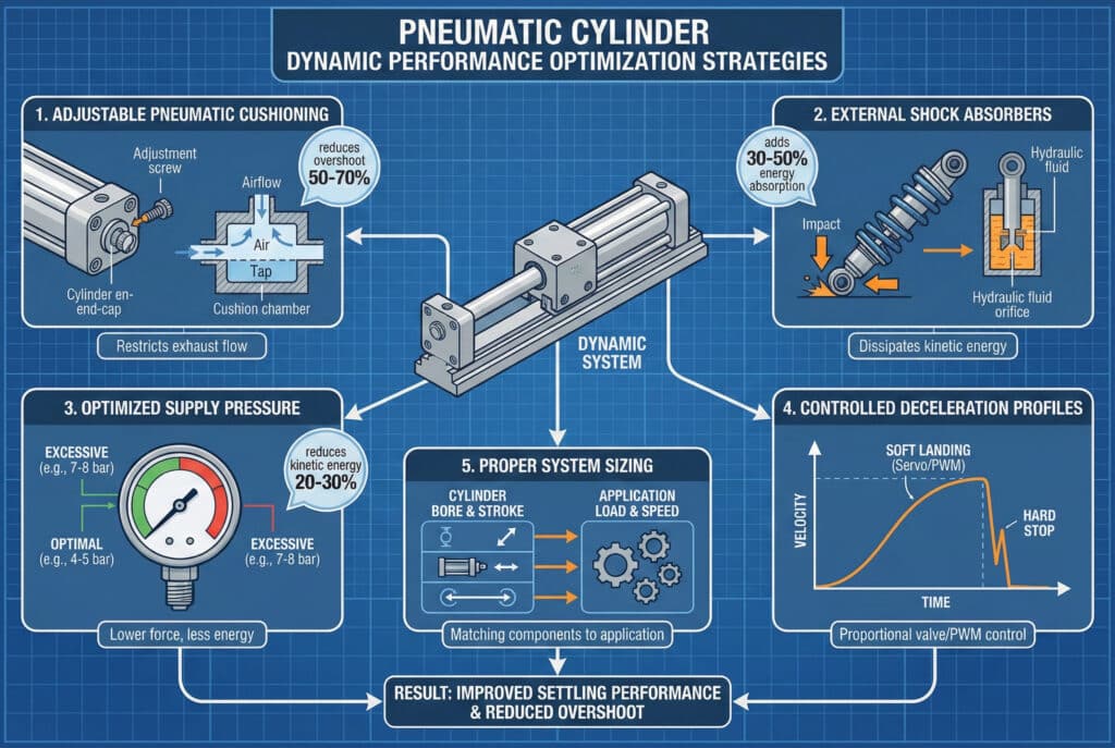
Pneumatic Cushioning Optimization
Modern rodless cylinders feature adjustable cushioning that restricts exhaust air flow during the final 10-30mm of travel. Proper adjustment is critical:
Cushioning Adjustment Procedure
- Start fully closed: Maximum restriction
- Run test cycle: Observe overshoot and settling
- Open 1/4 turn: Reduce restriction slightly
- Repeat testing: Find optimal balance
- Document setting: Record turns from closed position
Target: Minimal overshoot (2-3mm) with fastest settling (<100ms)
External Shock Absorber Selection
When built-in cushioning proves insufficient, external shock absorbers provide additional energy absorption:
| Shock Absorber Type | Energikapasitet | Justering | Kostnader | Beste applikasjon |
|---|---|---|---|---|
| Self-Adjusting | Medium | Automatisk | Høy | Variable belastninger |
| Adjustable Orifice | Middels-høy | Manuell | Medium | Fixed loads |
| Kraftig industriell | Svært høy | Manuell | Svært høy | Ekstreme forhold |
| Elastomer Bumpers | Lav | Ingen | Lav | Light-duty backup |
Avanserte kontrollstrategier
For applications requiring exceptional performance, consider:
- Proportional valve5 control: Gradual pressure reduction during approach
- PWM deceleration profiles: Digital control of stopping characteristics
- Position feedback loops: Real-time adjustment based on actual position
- Trykkmåling: Adaptive control based on load conditions
Our Bepto engineering team helps customers implement these solutions with our compatible rodless cylinder replacements, often achieving performance that matches or exceeds OEM specifications at 30-40% lower cost.
How Does Load Mass and Velocity Affect System Dynamics?
The relationship between mass, velocity, and dynamic performance follows predictable engineering principles. 📐
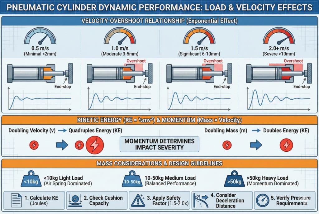
Load mass and velocity have exponential effects on overshoot and settling time: doubling velocity quadruples kinetic energy requiring four times the cushioning capacity, while doubling mass doubles energy linearly. The critical parameter is momentum (mass × velocity), which determines impact severity. Systems operating above 2 m/s with loads exceeding 50kg require careful engineering to achieve acceptable settling performance.
Velocity-Overshoot Relationship
Testing data from thousands of installations shows:
- 0.5 m/s: Minimal overshoot (<2mm), excellent settling
- 1,0 m/s: Moderate overshoot (3-5mm), good settling with proper cushioning
- 1,5 m/s: Significant overshoot (6-10mm), requires optimization
- 2.0+ m/s: Severe overshoot (>10mm), demands advanced solutions
Mass Considerations
Light loads (<10kg): Air spring effects dominate, may see oscillation
Medium loads (10-50kg): Balanced performance, standard cushioning adequate
Heavy loads (>50kg): Momentum dominates, external shock absorbers often required
Practical Design Guidelines
When specifying pneumatic slides for high-speed applications:
- Calculate kinetic energy: KE = ½mv² in joules
- Check cushioning capacity: Manufacturer specifications in joules
- Bruk sikkerhetsfaktor: 1.5-2.0× for reliability
- Consider deceleration distance: Longer cushions = gentler stopping
- Verify pressure requirements: Higher pressure increases cushioning effectiveness
At Bepto, we provide detailed technical specifications for all our rodless cylinder models, including cushioning capacity curves across different pressures and velocities. This data enables engineers to make informed decisions rather than guessing at component selection. 💪
Konklusjon
Systematic analysis and optimization of overshoot and settling time in high-speed pneumatic slides delivers measurable improvements in cycle time, positioning accuracy, and equipment longevity—transforming acceptable performance into competitive advantage through engineering fundamentals and proven solutions. 🚀
FAQs About Pneumatic Slide Dynamic Performance
Spørsmål: Hva er en akseptabel overskridelsesverdi for industrielle pneumatiske glidebaner?
For de fleste industrielle anvendelser er overskridelse mellom 2 og 5 mm akseptabelt og representerer godt innstilt demping. Presisjonsanvendelser som elektronikkmontering eller produksjon av medisinsk utstyr kan kreve <1 mm overskridelse, mens mindre kritisk materialhåndtering kan tåle 5–10 mm. Nøkkelen er konsistens – repeterbar overskridelse kan kompenseres i programmeringen, men tilfeldige variasjoner forårsaker kvalitetsproblemer.
Spørsmål: Hvordan vet jeg om dempingen er riktig justert?
Properly adjusted cushioning produces a soft “whoosh” sound rather than a hard metallic bang, minimal visible bounce at end-of-stroke, and consistent stopping position within ±2mm across multiple cycles. If you hear loud impacts, see excessive bounce, or experience position variation >5mm, your cushioning needs adjustment or your system requires external shock absorbers.
Spørsmål: Kan jeg redusere avsetningstiden ved å øke lufttrykket?
Ja, men med avtagende avkastning og potensielle ulemper. Å øke trykket fra 6 bar til 8 bar forbedrer vanligvis stabiliseringstiden med 15-25% ved å øke dempningseffektiviteten og systemstivheten. Trykk over 8 bar gir imidlertid sjelden ytterligere fordeler og øker luftforbruket, slitasjen og støynivået. Optimaliser dempningsjusteringen før du øker trykket.
Spørsmål: Hvorfor fungerer min pneumatiske glideanordning annerledes når den er varm sammenlignet med når den er kald?
Temperaturen påvirker lufttettheten, tetningsfriksjonen og smøremiddelets viskositet – alt dette påvirker den dynamiske ytelsen. Kaldt systemer (under 15 °C) viser økt friksjon og langsommere respons, mens varme systemer (over 40 °C) opplever redusert dempningseffektivitet når lufttettheten reduseres. Temperatursvingninger på 20 °C kan endre stabiliseringstiden med 30-40%. Vurder temperaturkompensert demping eller miljøkontroll for kritiske applikasjoner.
Spørsmål: Bør jeg bruke eksterne støtdempere eller stole på innebygd demping?
Built-in pneumatic cushioning should be your first choice—it’s integrated, cost-effective, and sufficient for most applications. Add external shock absorbers when: kinetic energy exceeds cushion capacity (typically >50 joules), you need adjustability for varying loads, built-in cushions are worn or damaged, or you’re operating at extreme velocities (>2 m/s). Our Bepto technical team can calculate your specific energy requirements and recommend appropriate solutions.
-
Understand the mechanics and applications of rodless pneumatic cylinders. ↩
-
Explore how damping forces dissipate energy to reduce mechanical oscillation. ↩
-
Review the operating principles of magnetic and optical linear encoders. ↩
-
Learn how Pulse Width Modulation (PWM) manages pneumatic flow control. ↩
-
Understand the function of proportional valves in precise motion control. ↩
