
Are you experiencing air leakage in your pneumatic systems? You’re not alone. Many engineers struggle with seal failures that cause efficiency losses, increased maintenance costs, and unexpected downtime. The right knowledge about sealing mechanisms can solve these persistent problems.
Sealing mechanisms in pneumatic systems work through controlled deformation of elastomeric materials1 against mating surfaces. Effective seals maintain contact pressure through compression (static seals) or through a balance of pressure, friction, and lubrication (dynamic seals), creating an impermeable barrier against air leakage.
I’ve been working with pneumatic systems for over 15 years at Bepto, and I’ve seen countless cases where understanding sealing principles has saved companies thousands in maintenance costs and prevented catastrophic system failures.
Table of Contents
- How Does O-ring Compression Ratio Affect Seal Performance?
- Why Is the Stribeck Curve Essential for Pneumatic Seal Design?
- What Causes Friction Heating in Dynamic Seals and How Can It Be Controlled?
- Conclusion
- FAQs About Pneumatic Sealing Mechanisms
How Does O-ring Compression Ratio Affect Seal Performance?
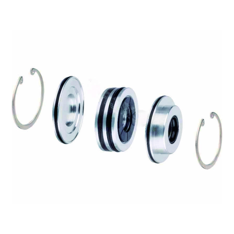
O-rings are perhaps the most common sealing elements in pneumatic systems, but their simple appearance hides complex engineering principles. The compression ratio is critical to their performance and longevity.
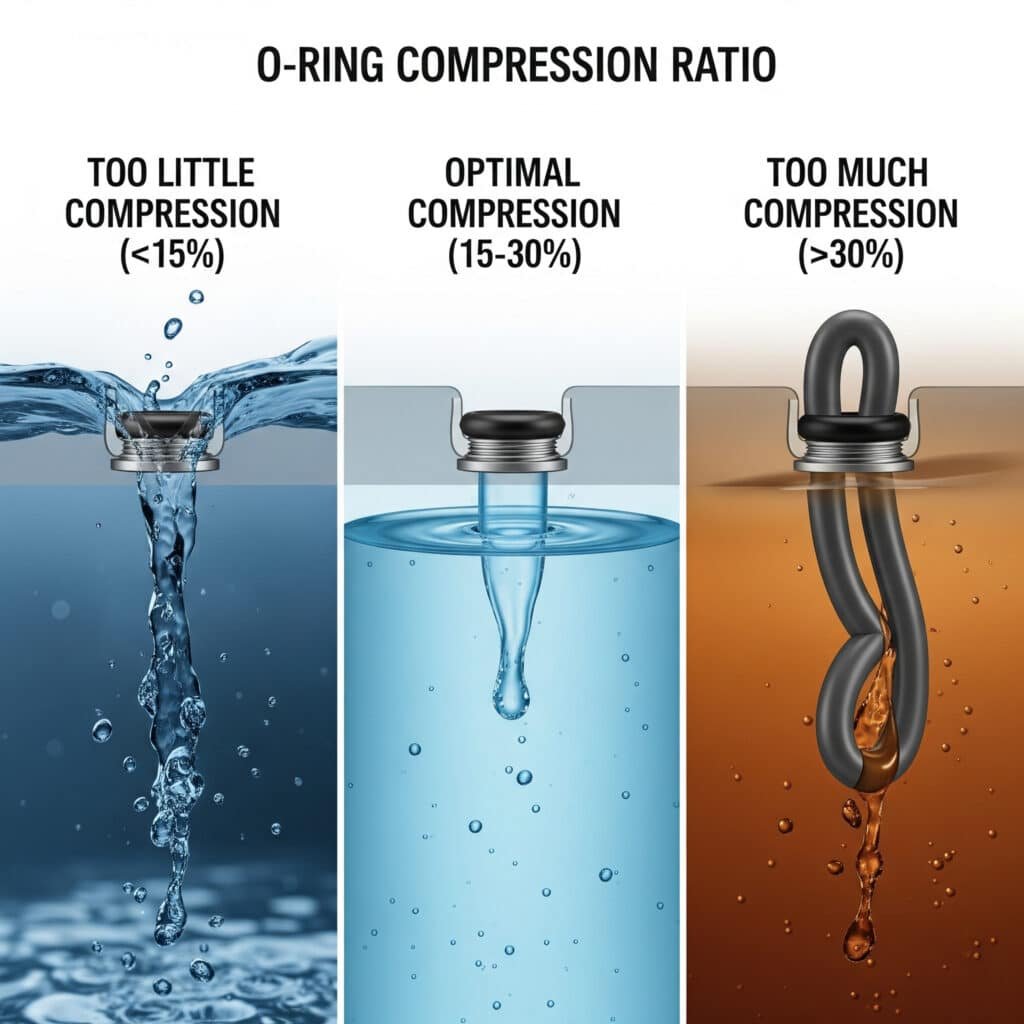
The O-ring compression ratio is the percentage of deformation from the original cross-section when installed. Optimal performance typically requires 15-30% compression. Too little compression causes leakage, while excessive compression leads to premature failure through extrusion, compression set2, or accelerated wear.
Getting the compression ratio right is more nuanced than many engineers realize. Let me share some practical insights from my experience with rodless cylinder sealing systems.
Calculating the Optimal O-ring Compression Ratio
The compression ratio calculation seems straightforward:
| Parameter | Formula | Example |
|---|---|---|
| Compression Ratio (%) | [(d – g)/d] × 100 | For 2.5mm O-ring in 2.0mm groove: [(2.5 – 2.0)/2.5] × 100 = 20% |
| Squeeze (mm) | d – g | 2.5mm – 2.0mm = 0.5mm |
| Groove Fill (%) | [π(d/2)²]/[w × g] × 100 | For 2.5mm O-ring in 3.5mm wide, 2.0mm deep groove: [π(2.5/2)²]/[3.5 × 2.0] × 100 = 70% |
Where:
- d = O-ring cross-section diameter
- g = groove depth
- w = groove width
Material-Specific Compression Guidelines
Different materials require different compression ratios:
| Material | Recommended Compression | Application |
|---|---|---|
| NBR (Nitrile) | 15-25% | General purpose, oil resistance |
| FKM (Viton) | 15-20% | High temperature, chemical resistance |
| EPDM | 20-30% | Water, steam applications |
| Silicone | 10-20% | Extreme temperature ranges |
| PTFE | 5-10% | Chemical resistance, low friction |
Last year, I worked with Michael, a maintenance engineer at a food processing plant in Wisconsin. He was experiencing frequent air leaks in his rodless cylinder systems despite using premium O-rings. After analyzing his setup, I discovered his groove design was causing over-compression (nearly 40%) of the NBR O-rings.
We redesigned the groove dimensions to achieve a 20% compression ratio, and his seal life improved from 3 months to over a year, saving his company thousands in maintenance costs and downtime.
Environmental Factors Affecting Compression Requirements
The optimal compression ratio isn’t static—it varies based on:
- Temperature fluctuations: Higher temperatures require lower compression to account for thermal expansion
- Pressure differentials: Higher pressures may require higher compression to prevent extrusion
- Dynamic vs. static applications: Dynamic seals typically need lower compression to reduce friction
- Installation methods: Stretch during installation can reduce effective compression
Why Is the Stribeck Curve Essential for Pneumatic Seal Design?
The Stribeck curve may sound academic, but it’s actually a powerful practical tool for understanding and optimizing seal performance in rodless pneumatic cylinders and other dynamic applications.
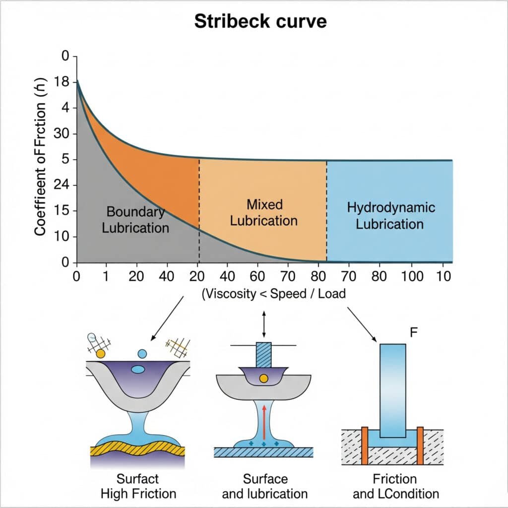
The Stribeck curve3 illustrates the relationship between friction coefficient, lubricant viscosity, speed, and load in sliding surfaces. In pneumatic seals, it helps engineers understand the transition between boundary, mixed, and hydrodynamic lubrication regimes, which is crucial for optimizing seal design for specific operating conditions.
Understanding this curve has practical implications for how your pneumatic systems perform in real-world conditions.
The Three Lubrication Regimes in Pneumatic Seals
The Stribeck curve identifies three distinct operating regimes:
| Lubrication Regime | Characteristics | Implications for Pneumatic Seals |
|---|---|---|
| Boundary Lubrication | High friction, direct surface contact | Occurs during start-up, slow speeds; causes stick-slip |
| Mixed Lubrication | Moderate friction, partial fluid film | Transition zone; sensitive to surface finish and lubricant |
| Hydrodynamic Lubrication4 | Low friction, complete fluid separation | Ideal for high-speed operation; minimal wear |
Practical Applications of the Stribeck Curve in Seal Selection
When selecting seals for rodless cylinders, understanding the Stribeck curve helps us:
- Match seal materials to operating conditions: Different materials perform better in different lubrication regimes
- Select appropriate lubricants: Viscosity requirements change based on speed and load
- Design optimal surface finishes: Roughness affects the transition between lubrication regimes
- Predict and prevent stick-slip phenomena: Critical for smooth operation in precision applications
Case Study: Eliminating Stick-Slip in Precision Positioning
I remember working with Emma, an automation engineer from a medical device manufacturer in Switzerland. Her rodless cylinder system was experiencing jerky motion (stick-slip) during slow-speed precision movements, affecting product quality.
By analyzing the application through the lens of the Stribeck curve, we determined her system was operating in the boundary lubrication regime. We recommended changing to a PTFE-based seal material with modified surface texture and a different lubricant formulation.
The result? Smooth motion even at 5mm/second, eliminating the quality issues and improving production yield by 15%.
What Causes Friction Heating in Dynamic Seals and How Can It Be Controlled?
Friction heating is often overlooked until it causes premature seal failure. Understanding this phenomenon is essential for designing reliable pneumatic systems with extended service life.
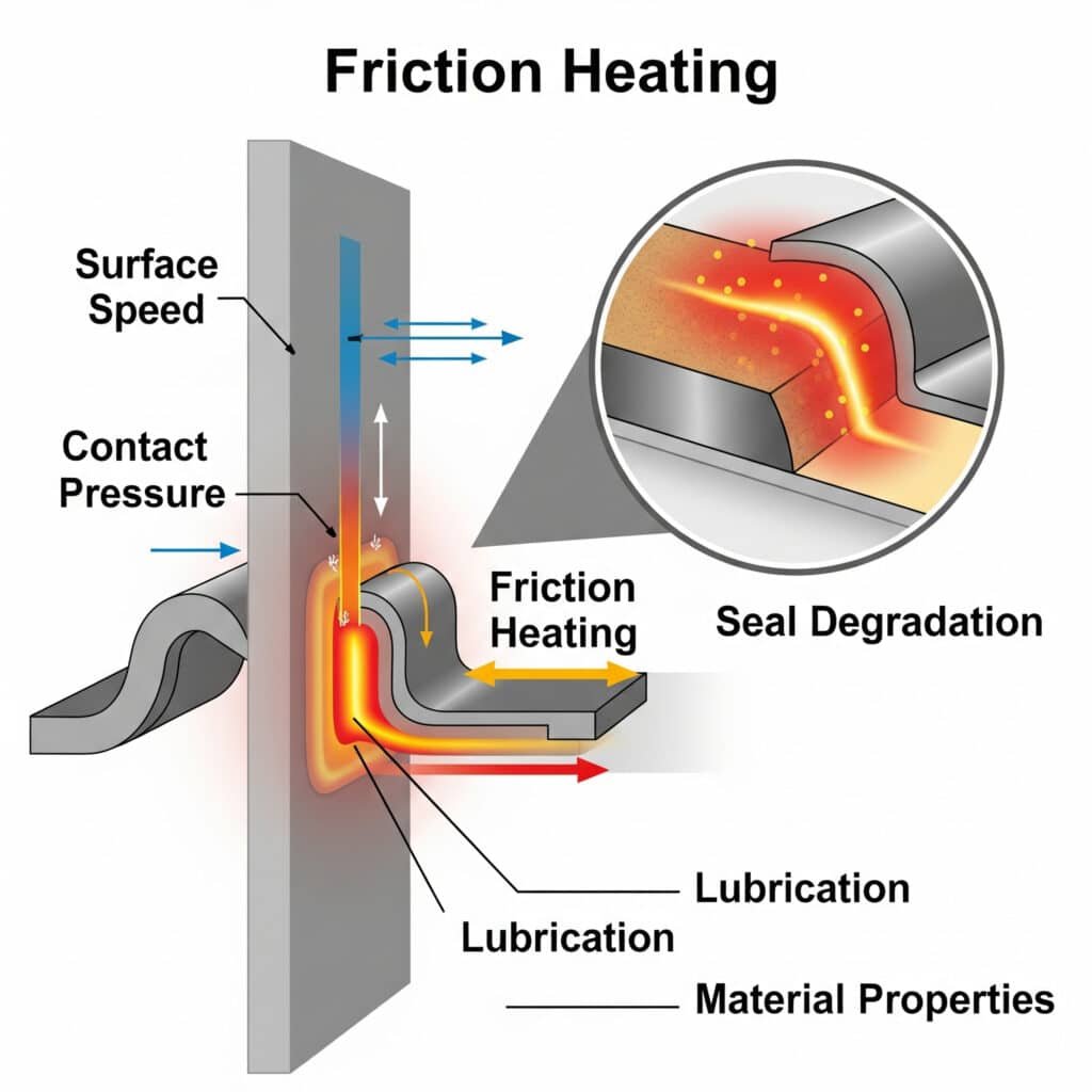
Friction heating5 in dynamic seals occurs when mechanical energy converts to thermal energy at the contact interface between the seal and mating surface. This heating is influenced by factors including surface speed, contact pressure, lubrication, and material properties. Excessive heating accelerates seal degradation through thermal breakdown of materials.
The consequences of friction heating can be severe, from reduced seal life to catastrophic failure. Let’s explore this phenomenon in more detail.
Quantifying Friction Heat Generation
The heat generated by friction can be estimated using:
| Parameter | Formula | Example |
|---|---|---|
| Heat Generation (W) | Q = μ × F × v | For μ=0.2, F=100N, v=0.5m/s: Q = 0.2 × 100 × 0.5 = 10W |
| Temperature Rise (°C) | ΔT = Q/(m × c) | For 10W heat, 5g seal, c=1.7J/g°C: ΔT = 10/(5 × 1.7) = 1.18°C/s |
| Steady-State Temp | Tss = Ta + (Q/hA) | Depends on heat transfer coefficient and surface area |
Where:
- μ = coefficient of friction
- F = normal force
- v = sliding velocity
- m = mass
- c = specific heat capacity
- Ta = ambient temperature
- h = heat transfer coefficient
- A = surface area
Critical Temperature Thresholds for Common Seal Materials
Different seal materials have different temperature limits:
| Material | Maximum Continuous Temp (°C) | Signs of Thermal Degradation |
|---|---|---|
| NBR (Nitrile) | 100-120 | Hardening, cracking, reduced elasticity |
| FKM (Viton) | 200-250 | Discoloration, reduced resilience |
| PTFE | 260 | Dimensional changes, reduced tensile strength |
| TPU | 80-100 | Softening, deformation, discoloration |
| UHMW-PE | 80-90 | Deformation, reduced wear resistance |
Strategies to Mitigate Friction Heating
Based on my experience with rodless cylinder applications, here are effective strategies to control friction heating:
- Optimize contact pressure: Reduce seal interference where possible without compromising sealing
- Improve lubrication: Select lubricants with appropriate viscosity and temperature stability
- Material selection: Choose materials with lower friction coefficients and higher thermal stability
- Surface engineering: Specify appropriate surface finish and coatings to reduce friction
- Heat dissipation design: Incorporate features that improve heat transfer away from seals
Real-World Application: High-Speed Rodless Cylinder Design
One of our customers in Germany operates high-speed packaging equipment with rodless cylinders running at speeds up to 2 m/s. Their original seals were failing after just 3 million cycles due to friction heating.
We conducted a thermal analysis and discovered localized temperatures reaching 140°C at the seal interface—well beyond the 100°C limit of their NBR seals. By switching to a composite PTFE seal with optimized contact geometry and improving the cylinder’s heat dissipation, we extended seal life to over 20 million cycles.
Conclusion
Understanding the science behind O-ring compression ratios, the Stribeck curve’s practical applications, and friction heating mechanisms provides the foundation for designing reliable, long-lasting pneumatic sealing systems. By applying these principles, you can select the right seals for your rodless cylinder applications, troubleshoot existing issues, and prevent costly failures before they occur.
FAQs About Pneumatic Sealing Mechanisms
What is the ideal compression ratio for O-rings in pneumatic applications?
The ideal compression ratio for O-rings in pneumatic applications is typically 15-25% for static seals and 10-20% for dynamic seals. This range provides sufficient sealing force while avoiding excessive compression that could lead to premature failure, especially in rodless cylinder applications.
How does the Stribeck curve help in selecting the right seal for my application?
The Stribeck curve helps by identifying which lubrication regime your application will operate in based on speed, load, and lubricant properties. For low-speed, high-load applications, choose seals optimized for boundary lubrication. For high-speed applications, select seals designed for hydrodynamic lubrication conditions.
What causes stick-slip motion in pneumatic cylinders and how can it be prevented?
Stick-slip motion is caused by the difference between static and dynamic friction coefficients, particularly in the boundary lubrication regime. Prevent it by using PTFE-based or other low-friction seal materials, applying appropriate lubricants, optimizing surface finishes, and ensuring proper seal compression for your rodless cylinder application.
How much temperature increase is acceptable for dynamic seals?
The acceptable temperature increase depends on the seal material. As a general rule, keep the operating temperature at least 20°C below the material’s maximum continuous temperature rating. For NBR (nitrile) seals common in rodless cylinders, keep temperatures below 80-100°C for extended service life.
What’s the relationship between seal hardness and compression requirements?
Harder seal materials (higher durometer) typically require less compression to achieve effective sealing. For example, a 90 Shore A material might need only 10-15% compression, while a softer 70 Shore A material might require 20-25% compression for the same sealing effectiveness in pneumatic applications.
How do I calculate the groove dimensions for an O-ring seal?
Calculate groove dimensions by determining the required compression ratio for your application and material. For a standard 25% compression of a 2.5mm O-ring, the groove depth would be 1.875mm (2.5mm × 0.75). Groove width should allow for 60-85% groove fill to permit controlled deformation without excessive stress.
-
Provides a foundational explanation of elastomers (polymers with viscoelasticity), which are the primary materials used for pneumatic seals due to their ability to deform and return to their original shape. ↩
-
Offers a technical definition of compression set, the permanent deformation of a seal after prolonged compressive stress, which is a primary cause of static seal failure. ↩
-
Details the principles of the Stribeck curve, a fundamental graph in the field of tribology that illustrates how friction between two lubricated surfaces is a function of viscosity, load, and speed. ↩
-
Explains the regime of hydrodynamic lubrication, an ideal state where a full, continuous fluid film completely separates two moving surfaces, resulting in minimal friction and wear. ↩
-
Describes the physics of frictional heating, the process by which mechanical energy is converted into thermal energy at a sliding interface, a critical factor in the thermal degradation of dynamic seals. ↩
