
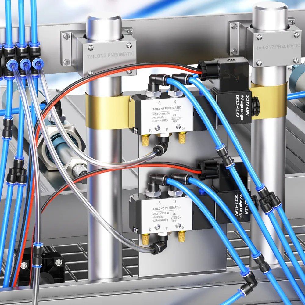
Are you experiencing unexpected hose failures, dangerous pressure drops, or chemical compatibility issues in your pneumatic systems? These common problems often stem from improper hose selection, leading to costly downtime, safety risks, and premature replacement. Choosing the right pneumatic hose can immediately solve these critical issues.
The ideal pneumatic hose must withstand your application’s specific bending requirements, resist chemical degradation from both internal and external exposures, and properly match with quick couplers to maintain optimal pressure and flow characteristics. Proper selection requires understanding bending fatigue standards, chemical compatibility factors, and pressure-flow relationships.
I remember consulting with a chemical processing plant in Texas last year where they were replacing pneumatic hoses every 2-3 months due to premature failures. After analyzing their application and implementing properly specified hoses with appropriate chemical resistance and bend radius ratings, their replacement frequency dropped to annual maintenance, saving over $45,000 in downtime and materials. Let me share what I’ve learned over my years in the pneumatic industry.
Table of Contents
- Understanding Bending Fatigue Testing Standards for Pneumatic Hoses
- Comprehensive Chemical Compatibility Reference Guide
- How to Match Quick Couplers for Optimal Pressure and Flow Performance
How Do Bending Fatigue Tests Predict Pneumatic Hose Lifespan in Dynamic Applications?
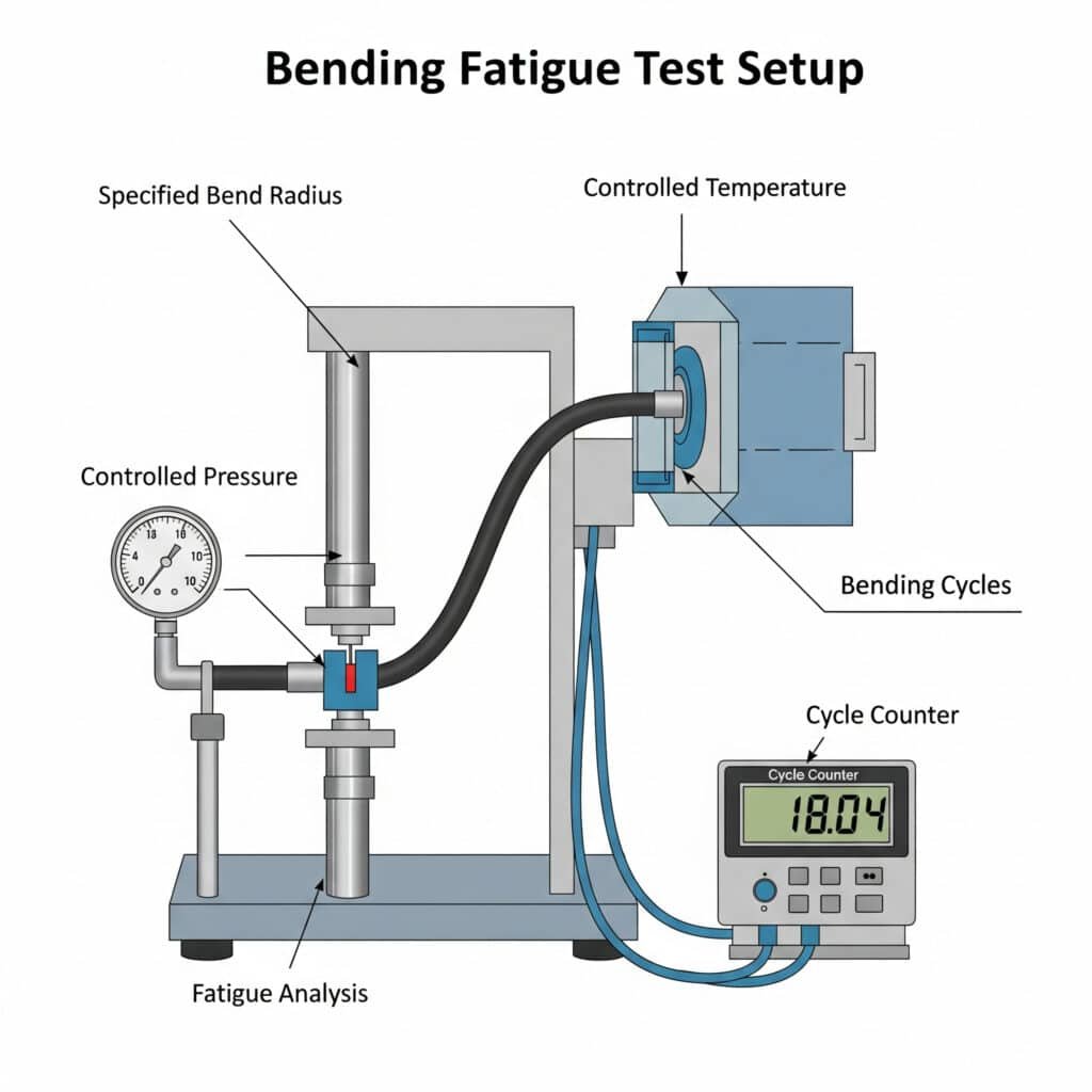
Bending fatigue testing provides critical data for selecting hoses in applications with continuous movement, vibration, or frequent reconfiguration.
Bending fatigue tests measure a hose’s ability to withstand repeated flexing without failure. Standard tests typically cycle hoses through specified bend radii at controlled pressures and temperatures, counting cycles until failure. Results help predict real-world performance and establish minimum bend radius specifications for different hose constructions.
Understanding Bending Fatigue Fundamentals
Bending fatigue failure occurs when a hose is repeatedly flexed beyond its design capabilities:
Failure mechanisms include:
– Inner tube cracking
– Reinforcement layer breakdown
– Cover abrasion and cracking
– Fitting connection failures
– Kinking and permanent deformationCritical factors affecting bending fatigue resistance:
– Hose construction materials
– Reinforcement design (spiral vs. braided)
– Wall thickness and flexibility
– Operating pressure (higher pressure = lower fatigue resistance)
– Temperature (extreme temperatures reduce fatigue resistance)
– Bend radius (tighter bends accelerate failure)
Industry Standard Testing Protocols
Several established test methods evaluate bending fatigue performance:
ISO 83311 Method
This international standard specifies:
- Test apparatus requirements
- Sample preparation procedures
- Test conditions standardization
- Failure criteria definitions
- Reporting requirements
SAE J517 Standard
This automotive/industrial standard includes:
- Specific test parameters for different hose types
- Minimum cycle requirements by application class
- Correlation to field performance expectations
- Safety factor recommendations
Bending Fatigue Test Procedures
A typical bending fatigue test follows these steps:
Sample preparation
– Condition hose at test temperature
– Install appropriate end fittings
– Measure initial dimensions and characteristicsTest setup
– Mount hose in test apparatus
– Apply specified internal pressure
– Set bend radius (typically 80-120% of minimum rated bend radius)
– Configure cycle rate (typically 5-30 cycles per minute)Test execution
– Cycle hose through specified bend pattern
– Monitor for leakage, deformation, or pressure loss
– Continue until failure or predetermined cycle count
– Record number of cycles and failure modeData analysis
– Calculate mean cycles to failure
– Determine statistical distribution
– Compare to application requirements
– Apply appropriate safety factors
Bending Fatigue Performance Comparison
| Hose Type | Construction | Average Cycles to Failure* | Minimum Bend Radius | Best Applications |
|---|---|---|---|---|
| Standard Polyurethane | Single layer | 100,000 – 250,000 | 25-50mm | General purpose, light duty |
| Reinforced Polyurethane | Polyester braid | 250,000 – 500,000 | 40-75mm | Medium duty, moderate flexing |
| Thermoplastic Rubber | Synthetic rubber with single braid | 150,000 – 300,000 | 50-100mm | General industrial, moderate conditions |
| Premium Polyurethane | Dual layer with aramid reinforcement2 | 500,000 – 1,000,000 | 50-100mm | High-cycle automation, robotics |
| Rubber (EPDM/NBR) | Synthetic rubber with dual braid | 200,000 – 400,000 | 75-150mm | Heavy duty, high pressure |
| Bepto FlexMotion | Specialized polymer with multi-layer reinforcement | 750,000 – 1,500,000 | 35-75mm | High-cycle robotics, continuous flexing |
*At 80% of maximum rated pressure, standard test conditions
Interpreting Minimum Bend Radius Specifications
The minimum bend radius specification is critical for proper hose selection:
- Static applications: Can operate at published minimum bend radius
- Occasional flexing: Use 1.5× minimum bend radius
- Constant flexing: Use 2-3× minimum bend radius
- High-pressure applications: Add 10% to bend radius for each 25% of maximum pressure
- Elevated temperatures: Add 20% to bend radius when operating near maximum temperature
Real-World Application Example
I recently consulted with a robotic assembly manufacturer in Germany who was experiencing frequent hose failures in their multi-axis robots. Their existing pneumatic lines were failing after approximately 100,000 cycles, causing significant downtime.
Analysis revealed:
- Required bend radius: 65mm
- Operating pressure: 6.5 bar
- Cycle frequency: 12 cycles per minute
- Daily operation: 16 hours
- Expected lifetime: 5 years (approximately 700,000 cycles)
By implementing Bepto FlexMotion hoses with:
- Tested fatigue life: >1,000,000 cycles at test conditions
- Multi-layer reinforcement designed for continuous flexing
- Optimized construction for their specific bend radius
- Specialized end fittings for dynamic applications
The results were impressive:
- Zero failures after 18 months of operation
- Maintenance costs reduced by 82%
- Downtime from hose failures eliminated
- Projected lifetime extended beyond 5-year target
Which Pneumatic Hose Materials Are Compatible with Your Chemical Environment3?
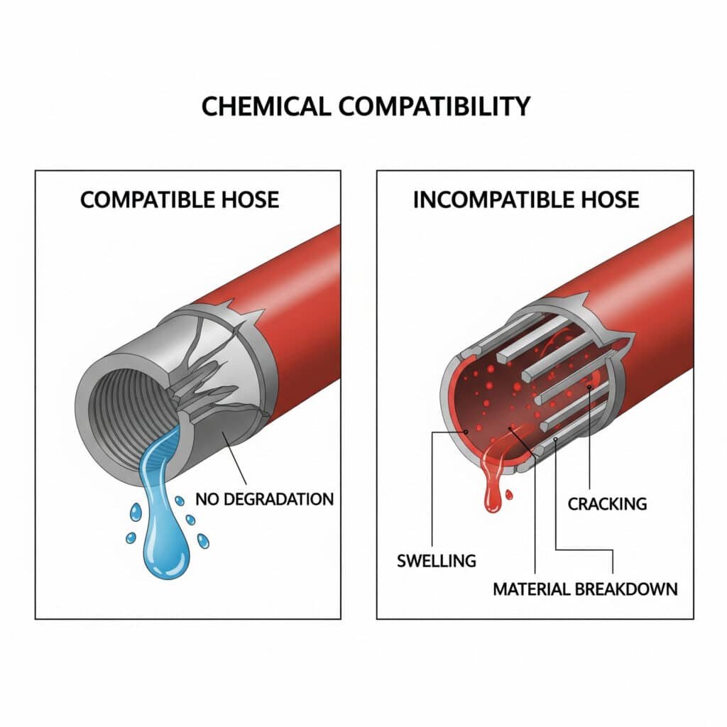
Chemical compatibility is crucial for ensuring hose longevity and safety in environments with exposure to oils, solvents, and other chemicals.
Chemical compatibility refers to a hose material’s ability to resist degradation when exposed to specific substances. Incompatible chemicals can cause swelling, hardening, cracking, or complete breakdown of hose materials. Proper selection requires matching hose materials to both internal media and external environmental exposures.
Understanding Chemical Compatibility Basics
Chemical compatibility involves several potential interaction mechanisms:
- Chemical absorption: Material absorbs chemical, causing swelling and softening
- Chemical adsorption: Chemical bonds to material surface, altering properties
- Oxidation: Chemical reaction degrades material structure
- Extraction: Chemicals remove plasticizers or other components
- Hydrolysis: Water-based breakdown of material structure
Comprehensive Chemical Compatibility Quick Reference Chart
This chart provides a quick reference for common hose materials and chemical exposures:
| Chemical | Polyurethane | Nylon | PVC | NBR (Nitrile) | EPDM | FKM (Viton) |
|---|---|---|---|---|---|---|
| Water | A | A | A | B | A | A |
| Air (with oil mist) | A | A | B | A | C | A |
| Hydraulic oil (mineral) | B | A | C | A | D | A |
| Synthetic hydraulic fluid | C | B | D | B | B | A |
| Gasoline | D | D | D | C | D | A |
| Diesel fuel | C | C | D | B | D | A |
| Acetone | D | D | D | D | C | C |
| Alcohols (methyl, ethyl) | B | B | B | B | A | A |
| Weak acids | C | C | B | C | A | A |
| Strong acids | D | D | D | D | C | B |
| Weak alkalis | B | D | B | B | A | C |
| Strong alkalis | C | D | C | C | A | D |
| Vegetable oils | B | A | C | A | C | A |
| Ozone | B | A | C | C | A | A |
| UV exposure | C | B | C | C | B | A |
Rating Key:
- A: Excellent (minimal or no effect)
- B: Good (minor effect, suitable for most applications)
- C: Fair (moderate effect, suitable for limited exposure)
- D: Poor (significant degradation, not recommended)
Material-Specific Chemical Resistance Properties
Polyurethane
- Strengths: Excellent resistance to oils, fuels, and ozone
- Weaknesses: Poor resistance to some solvents, strong acids, and bases
- Best applications: General pneumatics, oil-containing environments
- Avoid: Ketones, chlorinated hydrocarbons, strong acids/bases
Nylon
- Strengths: Excellent resistance to oils, fuels, and many solvents
- Weaknesses: Poor resistance to acids and prolonged water exposure
- Best applications: Dry air systems, fuel handling
- Avoid: Acids, high-moisture environments
PVC
- Strengths: Good resistance to acids, bases, and alcohols
- Weaknesses: Poor resistance to many solvents and petroleum products
- Best applications: Water, mild chemical environments
- Avoid: Aromatic and chlorinated hydrocarbons
NBR (Nitrile)
- Strengths: Excellent resistance to oils, fuels, and grease
- Weaknesses: Poor resistance to ketones, ozone, and strong chemicals
- Best applications: Oil-containing air, hydraulic systems
- Avoid: Ketones, chlorinated solvents, nitro compounds
EPDM
- Strengths: Excellent resistance to water, chemicals, and weathering
- Weaknesses: Very poor resistance to oils and petroleum products
- Best applications: Outdoor exposure, steam, brake systems
- Avoid: Any petroleum-based fluids or lubricants
FKM (Viton)
- Strengths: Outstanding chemical and temperature resistance
- Weaknesses: High cost, poor resistance to certain chemicals
- Best applications: Harsh chemical environments, high temperatures
- Avoid: Ketones, low-molecular-weight esters and ethers
Testing Methodology for Chemical Compatibility
When specific compatibility data isn’t available, testing may be necessary:
Immersion testing
– Immerse material sample in chemical
– Monitor for weight change, dimension change, and visual degradation
– Test at application temperature (higher temperatures accelerate effects)
– Evaluate after 24 hours, 7 days, and 30 daysDynamic testing
– Expose pressurized hose to chemical while flexing
– Monitor for leakage, pressure loss, or physical changes
– Accelerate testing with elevated temperatures if appropriate
Case Study: Chemical Compatibility Solution
I recently worked with a pharmaceutical manufacturing facility in Ireland that was experiencing frequent hose failures in their cleaning system. The system used a rotating set of cleaning chemicals including caustic solutions, mild acids, and sanitizing agents.
Their existing PVC hoses were failing after 3-4 months of service, causing production delays and contamination risks.
After analyzing their chemical exposure profile:
- Primary internal exposure: Alternating caustic (pH 12) and acidic (pH 3) solutions
- Secondary exposure: Sanitizing agents (peracetic acid based)
- External exposure: Cleaning agents and occasional chemical splashes
- Temperature range: Ambient to 65°C
We implemented a dual-material solution:
- EPDM-lined hoses for the caustic cleaning loops
- FKM-lined hoses for the acid and sanitizer loops
- Both with chemical-resistant outer covers
- Specialized connection system to prevent cross-contamination
The results were significant:
- Hose service life extended to over 18 months
- Zero contamination incidents
- Maintenance costs reduced by 70%
- Improved cleaning cycle reliability
How Do You Match Quick Couplers to Maintain Optimal Pressure and Flow in Pneumatic Systems?
Proper matching of quick couplers with hoses and system requirements is critical for maintaining pressure and flow performance.
Quick coupler selection significantly impacts system pressure drop and flow capacity. Undersized or restrictive couplers can create bottlenecks that reduce tool performance and system efficiency. Proper matching requires understanding flow coefficient (Cv) values, pressure ratings, and connection compatibility.
Understanding Quick Coupler Performance Characteristics
Quick couplers affect pneumatic system performance through several key characteristics:
Flow Coefficient (Cv)4
The flow coefficient indicates how efficiently a coupler passes air:
- Higher Cv values indicate less flow restriction
- Cv is directly related to coupler internal diameter and design
- Restrictive internal designs can significantly reduce Cv despite size
Pressure Drop Relationship
Pressure drop across a coupler follows this relationship:
ΔP = Q² / (Cv² × K)
Where:
- ΔP = Pressure drop
- Q = Flow rate
- Cv = Flow coefficient
- K = Constant based on units
This shows that:
- Pressure drop increases with the square of flow rate
- Doubling the flow rate quadruples the pressure drop
- Higher Cv values dramatically reduce pressure drop
Quick Coupler Selection Guide by Application
| Application | Required Flow Rate | Recommended Coupler Size | Minimum Cv Value | Maximum Pressure Drop* |
|---|---|---|---|---|
| Small hand tools | 0-15 SCFM | 1/4″ | 0.8-1.2 | 0.3 bar |
| Medium air tools | 15-30 SCFM | 3/8″ | 1.2-2.0 | 0.3 bar |
| Large air tools | 30-50 SCFM | 1/2″ | 2.0-3.5 | 0.3 bar |
| Very high flow | >50 SCFM | 3/4″ or larger | >3.5 | 0.3 bar |
| Precision control | Varies | Size for <0.1 bar drop | Varies | 0.1 bar |
*At maximum specified flow rate
Coupler-Hose Matching Principles
For optimal system performance, follow these matching principles:
Match flow capacities
– Coupler Cv should allow flow equal to or greater than hose capacity
– Multiple small couplers may not equal one properly sized coupler
– Consider all couplers in series when calculating system pressure dropConsider pressure ratings
– Coupler pressure rating must meet or exceed system requirements
– Apply appropriate safety factors (typically 1.5-2×)
– Remember that dynamic pressure spikes may exceed static ratingsEvaluate connection compatibility
– Ensure thread types and sizes are compatible
– Consider international standards if equipment is from multiple regions
– Verify that connection method is appropriate for pressure requirementsAccount for environmental factors
– Temperature affects pressure ratings (typically derated at higher temperatures)
– Corrosive environments may require special materials
– Impact or vibration may require locking mechanisms
Quick Coupler Flow Capacity Comparison
| Coupler Type | Nominal Size | Typical Cv Value | Flow @ 0.5 bar Drop* | Best Applications |
|---|---|---|---|---|
| Standard Industrial | 1/4″ | 0.8-1.2 | 15-22 SCFM | General purpose, hand tools |
| Standard Industrial | 3/8″ | 1.5-2.0 | 28-37 SCFM | Medium-duty tools |
| Standard Industrial | 1/2″ | 2.5-3.5 | 46-65 SCFM | Large air tools, main lines |
| High-Flow Design | 1/4″ | 1.3-1.8 | 24-33 SCFM | Compact high-flow applications |
| High-Flow Design | 3/8″ | 2.2-3.0 | 41-55 SCFM | Performance-critical tools |
| High-Flow Design | 1/2″ | 4.0-5.5 | 74-102 SCFM | Critical high-flow systems |
| Bepto UltraFlow | 1/4″ | 1.9-2.2 | 35-41 SCFM | Premium compact applications |
| Bepto UltraFlow | 3/8″ | 3.2-3.8 | 59-70 SCFM | High-performance tools |
| Bepto UltraFlow | 1/2″ | 5.8-6.5 | 107-120 SCFM | Maximum flow requirements |
*At 6 bar supply pressure
Calculating System Pressure Drop
To properly match components, calculate total system pressure drop:
Calculate individual component drops
– Hose: ΔP = (L × Q² × f) / (2 × d⁵)
– L = Length
– Q = Flow rate
– f = Friction factor
– d = Internal diameter
– Fittings/Couplers: ΔP = Q² / (Cv² × K)Sum all component pressure drops
– Total ΔP = ΔP₁ + ΔP₂ + … + ΔPₙ
– Remember that drops are cumulative through the systemVerify acceptable total pressure drop
– Industry standard: Maximum 10% of supply pressure
– Critical applications: Maximum 5% of supply pressure
– Tool-specific: Check manufacturer’s minimum pressure requirements
Practical Example: Quick Coupler Optimization
I recently consulted with an automotive assembly plant in Michigan that was experiencing performance issues with their impact wrenches. Despite having adequate compressor capacity and supply pressure, tools weren’t achieving specified torque.
Analysis revealed:
- Supply pressure at compressor: 7.2 bar
- Required tool pressure: 6.2 bar
- Tool air consumption: 35 SCFM
- Existing setup: 3/8″ hose with standard 1/4″ couplers
Pressure measurements showed:
- 0.7 bar drop across the quick couplers
- 0.4 bar drop across the hose
- Total pressure drop: 1.1 bar (15% of supply pressure)
By upgrading to Bepto UltraFlow components:
- 3/8″ high-flow couplers (Cv = 3.5)
- Optimized 3/8″ hose assembly
- Streamlined connections
The results were immediate:
- Pressure drop reduced to 0.4 bar total (5.5% of supply pressure)
- Tool performance restored to specification
- Productivity improved by 12%
- Energy efficiency improved due to lower required supply pressure
Quick Coupler Selection Checklist
When selecting quick couplers, consider these factors:
Flow requirements
– Calculate maximum flow rate needed
– Determine acceptable pressure drop
– Select coupler with appropriate Cv valuePressure requirements
– Identify maximum system pressure
– Apply appropriate safety factor
– Consider pressure fluctuations and surgesConnection compatibility
– Thread type and size
– International standards (ISO, ANSI, etc.)
– Existing system componentsEnvironmental considerations
– Temperature range
– Chemical exposure
– Mechanical stress (vibration, impact)Operational factors
– Connection/disconnection frequency
– One-handed operation requirements
– Safety features (safe disconnection under pressure)
Conclusion
Selecting the right pneumatic hose and connection system requires understanding bending fatigue performance, chemical compatibility factors, and pressure-flow relationships in quick couplers. By applying these principles, you can optimize system performance, reduce maintenance costs, and ensure safe, reliable operation of your pneumatic equipment.
FAQs About Pneumatic Hose Selection
How does bend radius affect the lifespan of a pneumatic hose?
Bend radius significantly impacts hose lifespan, especially in dynamic applications. Operating a hose below its minimum bend radius creates excessive stress on the inner tube and reinforcement layers, accelerating fatigue failure. For static applications, staying at or above the minimum specified bend radius is usually sufficient. For dynamic applications with continuous flexing, use 2-3 times the minimum bend radius to extend service life substantially.
What happens if I use a pneumatic hose with a chemical that’s incompatible with its material?
Using a hose with incompatible chemicals can lead to several failure modes. Initially, the hose may swell, soften, or become discolored. As exposure continues, the material may crack, harden, or delaminate. Eventually, this leads to leakage, rupture, or complete failure. Additionally, chemical attack can compromise the hose’s pressure rating, making it unsafe even before visible damage occurs. Always verify chemical compatibility before selection.
How much pressure drop is acceptable across quick couplers in a pneumatic system?
Generally, pressure drop across quick couplers should not exceed 0.3 bar (5 psi) at maximum flow rate for most applications. For the entire pneumatic system, total pressure drop should be limited to 10% of supply pressure (e.g., 0.6 bar in a 6 bar system). Critical or precision applications may require even lower pressure drops, typically 5% or less of supply pressure.
Can I use a larger diameter quick coupler to reduce pressure drop?
Yes, using a larger diameter quick coupler typically increases flow capacity and reduces pressure drop. However, the improvement follows a non-linear relationship—doubling the diameter increases flow capacity by approximately four times (assuming similar internal design). When upgrading, consider both the coupler’s nominal size and its flow coefficient (Cv), as internal design significantly impacts performance regardless of size.
How do I know when a pneumatic hose needs replacement due to bending fatigue?
Signs that a pneumatic hose is approaching failure due to bending fatigue include: visible cracking or crazing of the outer cover, particularly at bend points; unusual stiffness or softness compared to new hose; deformation that doesn’t recover when pressure is released; bubbling or blistering at the bend points; and slight leakage or “weeping” through the hose material. Implement a preventive replacement program based on cycle count or operating hours before these signs appear.
What’s the difference between working pressure and burst pressure for pneumatic hoses?
Working pressure is the maximum pressure at which the hose is designed to operate continuously under normal conditions, while burst pressure is the pressure at which the hose is expected to fail. Typically, burst pressure is 3-4 times the working pressure, providing a safety factor. Never operate a hose near its burst pressure. Also note that working pressure ratings typically decrease as temperature increases and as the hose ages or experiences wear.
-
Provides an overview of the ISO 8331 standard, which specifies a method for testing the fatigue life of rubber and plastics hoses under repeated flexing conditions, crucial for dynamic applications. ↩
-
Explains the properties of aramid fibers, a class of high-performance synthetic fibers known for their exceptional strength-to-weight ratio, heat resistance, and use as reinforcement in advanced composites and flexible materials. ↩
-
Offers a practical tool or comprehensive chart that allows users to check the resistance of various plastics and elastomers against a wide range of chemicals, which is essential for selecting the right hose material. ↩
-
Provides a technical definition of the Flow Coefficient (Cv), a standardized, dimensionless number that represents a valve’s or other component’s efficiency at allowing fluid flow, which is used to calculate pressure drop. ↩
