

Your linear actuator is binding, making grinding noises, and failing far sooner than expected – yet the load seems well within specifications. The hidden culprit destroying your equipment might be side loading, a force that acts perpendicular to your actuator’s intended motion. 🚨
Side loading on linear actuators refers to forces applied perpendicular to the actuator’s axis of motion, causing binding, premature wear, seal failure, and potential catastrophic damage – even small side loads can reduce actuator life by 70-90% compared to purely axial loading conditions. Understanding and eliminating side loading is critical for reliable actuator performance.
I recently worked with Tom, a machine designer at an automotive parts facility in Ohio, whose actuators were failing every three months instead of lasting three years because unrecognized side loading was destroying the internal components.
Table of Contents
- What Exactly Is Side Loading in Linear Actuators?
- How Does Side Loading Damage Linear Actuator Components?
- What Are the Common Causes of Side Loading?
- How Can You Prevent and Eliminate Side Loading Issues?
What Exactly Is Side Loading in Linear Actuators?
Side loading represents any force that acts perpendicular to the actuator’s intended line of motion, creating destructive stresses on components designed only for axial forces.
Side loading occurs when forces act at right angles to the actuator’s rod or shaft, creating bending moments that cause binding, misalignment, and accelerated wear of bearings, seals, and guide systems – even minimal side loads of 5-10% of the axial force rating can cause significant damage.

Understanding Force Vectors
Linear actuators are engineered to handle forces along their central axis. When forces act perpendicular to this axis, they create:
| Force Type | Direction | Actuator Design | Result |
|---|---|---|---|
| Axial Force | Along centerline | Designed for this | Optimal performance |
| Side Load | Perpendicular to axis | NOT designed for this | Damage and failure |
| Moment Load | Rotational around axis | Limited capability | Binding and wear |
The Physics of Side Loading
When side loading occurs, the actuator rod acts like a lever arm, multiplying the perpendicular force and creating enormous stresses at bearing and seal locations. A 100-pound side load applied 6 inches from the bearing can create 600 pound-inches of bending moment1 – far exceeding most actuator capabilities.
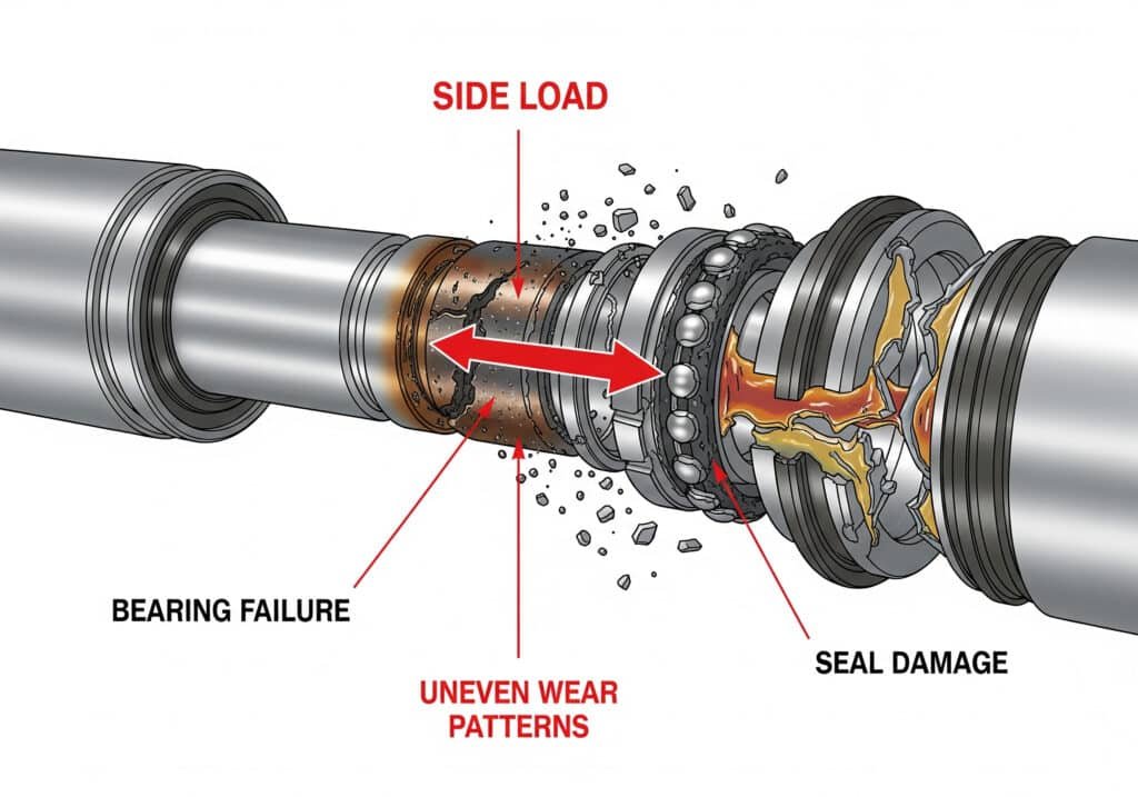
Visual Identification
Common signs of side loading include:
- Rod scoring or scratches
- Uneven seal wear patterns
- Binding during operation
- Premature bearing failure
- Misalignment of connected components
How Does Side Loading Damage Linear Actuator Components?
Side loading creates a cascade of destructive effects throughout the actuator’s internal systems, leading to rapid and often catastrophic failure.
Side loading damages linear actuators by creating excessive bearing loads, distorting sealing surfaces, causing rod buckling2, generating uneven wear patterns, and overloading guide systems – typically resulting in seal failure, bearing destruction, and complete actuator replacement within months rather than years.
Bearing System Destruction
Linear actuator bearings are designed for radial loads along the axis, not perpendicular forces. Side loading causes:
- Point loading instead of distributed forces
- Accelerated wear on bearing surfaces
- Heat generation from increased friction
- Premature failure of bearing races and balls
Seal System Compromise
Side loading distorts the actuator rod, creating:
- Uneven seal contact pressure
- Premature seal extrusion and tearing
- Fluid leakage past damaged seals
- Contamination entry through compromised sealing
Real-World Damage Assessment
Lisa, a maintenance supervisor at a food processing plant in Wisconsin, shared her experience with side loading damage. Her facility’s actuators were failing every 4-6 months with:
- 80% seal failure rate
- Complete bearing replacement needed
- $15,000 annual replacement costs
- 2-3 days downtime per failure
After implementing proper side load elimination with Bepto’s guidance, her actuator life increased to over 2 years with minimal maintenance.
What Are the Common Causes of Side Loading?
Identifying side loading sources is essential for preventing actuator damage and ensuring reliable system operation.
Common side loading causes include misaligned mounting brackets, flexible connections without proper support, off-center load application, thermal expansion3 effects, worn guide systems, and improper actuator sizing – with mounting misalignment being responsible for over 60% of side loading failures.
Mounting and Alignment Issues
Poor Mounting Practices:
- Misaligned mounting brackets
- Inadequate support structures
- Flexible mounting surfaces
- Thermal expansion not accommodated
Alignment Tolerances:
- Angular misalignment > 0.1 degrees
- Parallel offset > 0.005 inches per foot
- Mounting surface deflection under load
Load Application Problems
Off-Center Loading:
- Loads applied away from actuator centerline
- Unbalanced multi-point connections
- Eccentric load distributions
- Dynamic load shifts during operation
System Design Deficiencies
Inadequate Support Systems:
- Missing linear guides or rails
- Insufficient structural rigidity
- Flexible connections without proper constraints
- Undersized support components
Environmental Factors
External conditions contributing to side loading:
- Thermal expansion causing misalignment
- Vibration creating dynamic side loads
- Settling of mounting structures over time
- Wear in connected components
How Can You Prevent and Eliminate Side Loading Issues?
Implementing proper design practices and support systems can eliminate side loading and dramatically extend actuator life.
Prevent side loading through precise alignment during installation, external linear guides for load support, flexible couplings to accommodate misalignment, proper mounting bracket design, and regular maintenance inspections – with External Linear Guides4 being the most effective solution for high-load applications.
Design Solutions
External Linear Guides:
The most effective solution for eliminating side loading is using external linear guides or rails to carry all perpendicular forces, allowing the actuator to provide only axial motion.
Flexible Coupling Systems:
- Universal joints for angular misalignment
- Bellows couplings for thermal expansion
- Spherical bearings for multi-axis flexibility
Installation Best Practices
Precision Alignment Procedures:
- Use laser alignment tools for critical applications
- Verify mounting surface flatness and rigidity
- Allow for thermal expansion in bracket design
- Implement adjustable mounting systems
Support Structure Requirements:
- Mounting surfaces must be rigid and well-supported
- Bracket deflection under full load < 0.001 inches
- Use dowel pins for precise positioning
- Implement vibration isolation where needed
Bepto’s Side Loading Solutions
Our rodless cylinder designs inherently resist side loading better than traditional rod-style actuators because:
- Larger bearing surfaces distribute loads more effectively
- Integrated guide systems handle perpendicular forces
- Robust construction withstands misalignment better
- Modular mounting options accommodate various installations
We recently helped Michael, an engineer at a packaging machinery company in North Carolina, eliminate chronic side loading issues by replacing traditional cylinders with our guided rodless units, reducing his maintenance costs by 75% while improving system reliability.
Maintenance and Monitoring
Regular Inspection Points:
- Check for rod scoring or unusual wear patterns
- Monitor seal condition and leakage
- Verify mounting alignment periodically
- Document performance trends over time
Preventive Measures:
- Implement alignment checks during scheduled maintenance
- Replace worn guide components before failure
- Monitor system performance for early warning signs
- Train maintenance staff on side loading identification
Conclusion
Side loading is the silent killer of linear actuators – invest in proper design and support systems to protect your equipment investment. 🛡️
FAQs About Side Loading on Linear Actuators
Q: How much side loading can a typical linear actuator handle?
Most linear actuators can handle only 2-5% of their axial force rating as side loading, with even small perpendicular forces causing significant damage and shortened service life.
Q: Can I fix side loading problems after installation?
Yes, through realignment procedures, adding external guide systems, installing flexible couplings, or upgrading to actuators with better side load resistance, though prevention during design is always more cost-effective.
Q: What’s the difference between side loading and moment loading?
Side loading refers to perpendicular forces, while moment loading involves rotational forces around the actuator axis – both are destructive, but moment loads can often be addressed with proper coupling design.
Q: Do rodless cylinders handle side loading better than rod-style actuators?
Yes, rodless cylinders typically have better side load resistance due to larger bearing surfaces, integrated guide systems, and more robust construction, making them ideal for applications with potential misalignment.
Q: How do I calculate the side loading in my application?
Measure perpendicular forces using load cells or calculate based on geometry and applied loads – any force not acting along the actuator’s centerline contributes to side loading and should be minimized or eliminated.
-
Explore this key engineering concept that describes the reaction induced in a structural element when an external force is applied. ↩
-
Understand the principles of structural instability where a slender column under compression suddenly fails. ↩
-
Learn about the physical property of materials that causes them to change shape in response to temperature changes. ↩
-
Discover the different kinds of external guide systems used to support loads and ensure precise linear motion. ↩
