

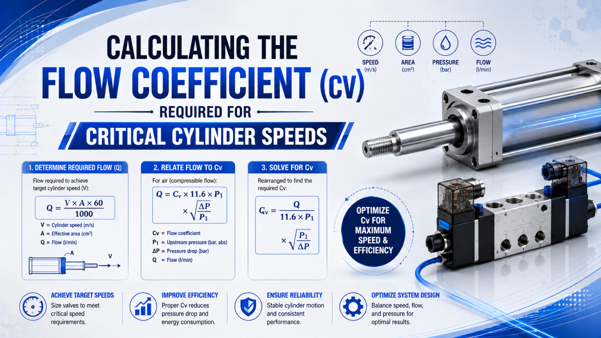
Flow coefficient Cv starts with the motion requirement. Record the cylinder bore, rod diameter, stroke, direction, working pressure, permitted stroke time, and load condition before selecting a valve. Next, calculate the directional free-air demand. Finally, apply the valve manufacturer’s compressible-flow method at stated inlet and outlet conditions.
At 5.5 bar supply and 0.35 bar valve pressure drop, Parker’s P1P guide assigns Cv 1.01 to a 63 mm cylinder moving at 500 mm/s (Parker, accessed 2026). Change the pressure allowance, bore, direction, or speed and the required capacity changes too.
Key Takeaways
- Convert bore, stroke, pressure, and target time into directional free-air demand.
- Use the valve maker’s gas-flow equation, curve, or ISO 6358 data.
- Check supply and exhaust paths separately.
- Validate stroke time with dynamic pressure measurements before approving the valve.
Why Must Cylinder Speed Be Converted Into a Flow Requirement First?
Under one defined pressure condition, Parker’s cylinder-to-valve table spans Cv 0.01 to 2.56 across 20-100 mm bores and 50-500 mm/s speeds (Parker, accessed 2026). That range shows why speed alone cannot select a valve: chamber area determines how much air the motion consumes.
Directional free-air demand is the normalized flow required to fill one cylinder chamber within its permitted travel time. Start with average piston speed:
Here, is average speed, is stroke, and is the permitted travel time. Average speed is a cycle-planning input. It does not describe the acceleration peak, cushion phase, breakaway friction, or load-induced pressure change.
Calculate the cap-end area for extension:
Retraction uses the pressurized annular area:
is bore diameter and is rod diameter. Multiplying the applicable area by stroke gives the geometric chamber volume:
This first step prevents a common selection error. That difference matters: a valve that moves a 32 mm cylinder at the target speed may be far too restrictive for a 100 mm cylinder, even if both cylinders use the same nominal port thread.
Treat the speed target as two directional jobs. Extension and retraction have different chamber volumes, while a directional valve may also publish different flow ratings for supply-to-cylinder and cylinder-to-exhaust paths. One headline Cv can hide the path that actually controls the cycle.
How Do You Estimate the Cylinder’s Free-Air Demand?
With a 63 mm bore and 500 mm stroke, the cap-end geometric volume is 1.559 L. Filling that chamber to 5.5 bar gauge requires roughly 600 standard L/min when the stroke must finish in one second. Pressure ratio creates the difference, not geometric volume alone.
At equal gas and reference temperatures, use this initial estimate:
Use and in SI units. Express in seconds. is the required chamber pressure in bar absolute, and is the stated reference pressure in bar absolute. Apply to convert cubic metres per second to litres per minute.
The equation estimates ideal normalized chamber demand. It excludes port cavities and tube volume. Valve switching time and leakage are omitted too. Temperature change and the pressure gradient needed to accelerate a loaded piston require separate treatment. Do not hide those effects inside an undocumented efficiency percentage.
Reference conditions control the comparison. SCFM can differ from NL/min and standard m³/h because their reference temperatures or pressures may not match. Before comparing numbers, record the convention used by the calculator, flow meter, and valve catalog. The calculator provides a demand estimate for valve and tubing pre-selection. Treat the higher directional result as an input to the next step, not as a promised valve output. Match its standard-flow convention to the catalog before comparing numbers. If the supplier publishes several pressure points or flow directions, use the one representing the installed route. A larger flow measured under easier conditions does not prove that the valve will supply the calculated demand at the machine’s actual pressure ratio.
Which Flow Coefficient Cv Method Should You Use for Compressed Air?
ISO 6358-1 defines steady-state testing for pneumatic components using compressible fluids and was confirmed in 2022, with a measurement-uncertainty amendment published in 2026 (ISO, 2013/2026). Pneumatic data expressed as sonic conductance and critical pressure ratio should therefore stay within its compressible-flow model.
Sonic conductance is an ISO 6358 flow-capacity parameter determined through compressible-fluid testing. It is not a liquid Cv value with different units.
Use the method that matches the supplier’s published data:
| Available valve data | Correct sizing route | Information still required |
|---|---|---|
| Gas Cv equation or gas-flow calculator | Enter required standard flow, upstream absolute pressure, downstream absolute pressure, temperature, and gas properties | Exact flow path and unit convention |
| Cv chart for cylinder bore and speed | Use only within the chart’s stated supply pressure, pressure drop, and motion range | Bore, direction, target speed, and installation losses |
| ISO 6358 sonic conductance and critical pressure ratio | Apply the manufacturer’s ISO 6358 sizing method or software | Upstream and downstream absolute pressures and reference conditions |
| Flow curve in NL/min or SCFM | Read capacity at the actual pressure ratio, not at an unrelated catalog point | Standard-flow definition and permissible pressure loss |
| Port size only | Request tested flow data | Cv, Kv, and , or a pressure-flow curve |
Swagelok’s gas Cv calculator asks for inlet pressure, outlet pressure, flow, temperature, medium, and specific gravity; its pressure instructions distinguish absolute pressure from psig (Swagelok, accessed 2026). Any calculator using only flow, specific gravity, and pressure drop applies a liquid relationship. It is not sufficient for this pneumatic task.
Flow regime also matters. In ISO 6358 data, the component-specific value marks the critical back-pressure ratio. Once the downstream-to-upstream absolute-pressure ratio crosses that boundary, lowering downstream pressure does not increase mass flow in the same way. Use the tested valve value instead of a universal ratio. Check which working path produced the reported and values because supply-to-cylinder and cylinder-to-exhaust data may differ. The relevant result is the path used during the timed motion, not the largest number anywhere on the datasheet.
Worked Example: A 63 mm Cylinder at 500 mm/s
Parker’s P1P guide uses 5.5 bar supply and 0.35 bar allowed valve drop. Under those conditions, it lists Cv 1.01 for a 63 mm cylinder moving at 500 mm/s (Parker, accessed 2026). This worked calculation reproduces the catalog result rather than inventing a multiplier.
Use these inputs:
| Input | Value | Role in the calculation |
|---|---|---|
| Bore | 63 mm | Sets cap-end area |
| Rod diameter | 20 mm | Sets annular rod-side area |
| Stroke | 500 mm | Sets chamber displacement |
| Target stroke time | 1.0 s | Sets average speed and demand |
| Supply pressure | 5.5 bar(g) | Selects the pressure basis |
| Permitted valve drop | 0.35 bar | Selects Parker’s sizing constant |
| Reference pressure | 1.01325 bar(abs) | Defines normalized flow |
The cap-end area is , and the annular rod-side area is . Those areas produce geometric volumes of 1.559 L and 1.402 L.
Using and the initial free-air equation gives:
| Direction | Geometric volume | Idealized free-air demand |
|---|---|---|
| Extension | 1.559 L | 600 NL/min |
| Retraction | 1.402 L | 539 NL/min |
The extension side controls the initial flow requirement for equal one-second strokes. Different time targets can reverse that conclusion. Load and cushion settings also matter. So does path capacity.
Parker’s US-unit sizing relationship can be written as:
is cylinder area in square inches. Use for stroke in inches and for time in seconds. At 80 psig, Parker’s table gives compression factor . It gives constant for a 5 psi pressure-drop allowance.
Substitution for this 63 mm by 500 mm cylinder gives:
The calculation and Parker’s metric chart agree at Cv 1.01 because they use the same pressure basis and pressure-drop allowance. Practically, choose a valve whose relevant flow path meets or exceeds that requirement under matching conditions. Then inspect the rest of the installed route.
This agreement is a useful engineering cross-check. If a hand calculation and the manufacturer’s cylinder-speed chart differ materially, stop before selecting a valve. For example, mixed gauge and absolute pressure are common causes. A wrong bore area is another possibility. Check for unmatched standard-flow conditions and formulas taken from another supplier’s test convention.
How Do Supply and Exhaust Restrictions Change the Result?
Parker states that each flow path through a directional valve has its own Cv (Parker valve guidance, accessed 2026). Its cylinder guidance warns that insufficient tube bore limits speed and excessive tube volume increases filling time (Parker cylinder guidance, accessed 2026). Required Cv therefore belongs to a route, not an isolated valve body.
During extension, air must pass through the supply port, valve gallery, working port, fitting, tube, and cap-end port. At the same time, rod-side air escapes through another fitting, tube, speed controller, valve exhaust gallery, and silencer. A filling-path restriction reduces the pressure available to accelerate the load. An exhaust restriction creates back pressure and reduces net cylinder force even when the upstream gauge looks steady. Either route can set the actual speed, so the pressure traces must identify which side consumes the available margin before a larger valve is specified.
| Restriction | Typical evidence | Selection consequence |
|---|---|---|
| FRL or regulator | Pressure falls before the valve during motion | Valve Cv alone cannot restore missing inlet pressure |
| Manifold supply gallery | Several actuators slow when shifting together | Check simultaneous flow and shared supply capacity |
| Push-in fitting or elbow | Internal bore is smaller than tube ID | Include the fitting in the pressure-loss review |
| Long tube | Delay and pressure loss grow with length | Compare actual ID and length, not outside diameter |
| Meter-out speed controller | Back pressure rises on the exhausting chamber | Confirm full-open flow capacity before blaming the valve |
| Silencer | Cylinder improves when a verified clean test exhaust is used | Replace or correctly size the silencer |
| Cushion restriction | Speed changes near end of stroke only | Tune cushioning separately from mid-stroke valve sizing |
For more detail on installed restrictions, compare the hose and fitting size guide and the silencer clogging analysis.
How Should You Validate the Selected Valve?
CAGI recommends no more than 10% total pressure drop between compressor discharge and the point of use in a well-designed compressed-air system (CAGI, accessed 2026). Because the valve uses only part of that pressure budget, validation must capture pressure at the valve and cylinder while the actuator is moving.
Use a repeatable acceptance test:
- Record supply pressure at the valve inlet before motion and during the fastest part of the stroke.
- Measure the pressure in the filling chamber and, when practical, the back pressure in the exhausting chamber.
- Time extension and retraction separately over the defined travel.
- Repeat the measurement with the normal load, cushion settings, speed-controller settings, and simultaneous machine demand.
- Compare the trace with the valve maker’s test conditions and the target stroke-time tolerance.
Dynamic pressure validation is a comparison of pressures measured while the cylinder is moving. Static pressure alone cannot prove flow capacity. For instance, regulators, filters, manifold galleries, and small fittings may hold the expected pressure at rest yet collapse during demand. Meanwhile, a large drop across a speed controller may be intentional for stable meter-out control. Do not validate a valve by temporarily removing every restriction and reporting only the fastest stroke. That test can isolate a bottleneck, but the acceptance test must use the production configuration, including the guards, load, silencers, flow controls, and normal upstream demand.
A useful diagnostic compares two traces instead of one number: valve-inlet pressure against filling-chamber pressure, then exhausting-chamber pressure against atmosphere. Supply-side difference tests inlet capacity. Exhaust-side difference reveals back pressure. Together they show whether a larger directional valve can actually improve the cycle.
See The Importance of Valve Flow (Cv) in System Performance for a broader diagnostic sequence. Use the dedicated solenoid-valve stroke-time sizing workflow when valve switching belongs in the timing budget.
What Data Should Go Into a Cv Sizing Worksheet?
One Parker method uses cylinder area, stroke, compression factor, allowed pressure drop, and stroke time (Parker, accessed 2026). Swagelok’s gas method also needs upstream pressure, downstream pressure, temperature, and gas properties (Swagelok, accessed 2026). Purchase specifications must identify the chosen convention.
| Worksheet field | Required entry | Why it matters |
|---|---|---|
| Cylinder geometry | Bore, rod diameter, stroke, number of cylinders | Establishes extension and retraction volumes |
| Motion target | Directional stroke time, dwell, cycle rate | Separates peak point-of-use demand from average consumption |
| Load and orientation | Moving mass, friction, vertical or horizontal axis | Determines the chamber pressure needed during motion |
| Pressure basis | Gauge or absolute, measured location, minimum dynamic value | Prevents pressure-ratio errors |
| Flow reference | SCFM, NL/min, standard m³/h, reference temperature and pressure | Makes catalog and calculated flow comparable |
| Valve capacity | Path-specific Cv/Kv, ISO 6358 and , or flow curve | Identifies the tested rating used for selection |
| Installed conductors | Fitting bore, tube ID and length, manifold passage | Captures restrictions outside the valve |
| Exhaust hardware | Speed controller, silencer, quick exhaust device | Identifies back-pressure limits |
| Acceptance criteria | Maximum stroke time, repeat count, load state, pressure limits | Converts selection into a testable result |
Missing conditions make a flow value incomplete. Neither port size nor one unlabeled capacity figure establishes cylinder speed. When the application still needs review, send the completed worksheet through the contact page so the supplier can check the pressure basis, flow path, conductors, exhaust hardware, and acceptance target.
Final Selection Rule
Under Parker’s stated 5.5 bar supply, 0.35 bar valve drop, and 500 mm/s target, the 63 mm example reaches Cv 1.01 (Parker, accessed 2026). Keep those conditions beside the result. Then select the relevant flow paths and verify the installed motion.
Follow this sequence:
- Define directional speed or stroke time.
- Calculate cap-end and rod-side volumes.
- Convert each motion into standard-flow demand using explicit reference conditions.
- Apply the exact gas Cv method, ISO 6358 method, or performance curve supplied for the valve.
- Check every installed restriction in both directions.
- Measure dynamic pressure and actual stroke time.
Cv only screens candidates. Final choice must meet the timed motion at stable pressure. It must also preserve controllable acceleration and acceptable exhaust back pressure while documenting the production test margin.
Read What Is Flow Coefficient Cv and How Does It Determine Valve Sizing for Pneumatic Systems? for foundational terminology. Laboratory characterization uses a different workflow, covered in How to Calculate Flow Coefficient (Cv) from Valve Test Data.
Cylinder Speed and Valve Cv FAQs
Within Parker’s stated conditions, required Cv changes from 0.10 to 1.01 for the same 63 mm bore as speed rises from 50 to 500 mm/s (Parker, accessed 2026). These answers address the assumptions most likely to invalidate that kind of calculation.
Can I use a liquid Cv calculator for compressed air?
No. Liquid calculators normally use an incompressible pressure-drop relationship. Compressed-air sizing needs upstream and downstream absolute pressure. Temperature and standard-flow conditions must also be defined. Finish the calculation with a gas equation, pressure-flow curve, or tested pneumatic data published for the exact valve.
Does a calculated Cv of 1.01 guarantee 500 mm/s?
No. Cv 1.01 matches the Parker example only at its stated bore and target speed. Supply pressure and valve drop must match too; installed conductors and exhaust hardware can still slow the motion. Load, cushioning, and simultaneous demand also matter. Verify dynamic pressures and production stroke time.
Should extension and retraction use the same Cv?
Not automatically. Single-rod cylinders have different cap-end and rod-side areas; directional valves can have unequal capacity across their working paths. Calculate each motion from its own time target. Then check both the filling route and the exhausting route before using the harder requirement.
What if the catalog lists only NL/min instead of Cv?
Matching conditions are mandatory. Confirm the two pressures and the standard-flow reference. Flow direction and valve state must also match. If any item is missing, request a pressure-flow curve or ISO 6358 data instead of converting an unlabeled number with a liquid equation.
Sources and technical references
The source set contains one ISO standard record; four manufacturer sizing or product references; one CAGI pressure-drop brief; and one official instructional video. Retrieval dates keep the equations and chart conditions traceable. They also make later checks of each selection boundary straightforward.
- ISO 6358-1:2013, steady-state flow-rate testing of pneumatic components using compressible fluids, including 2020 and 2026 amendments. Retrieved 2026-07-23.
- Parker P1P Compact ISO Cylinders Catalog, the source for the 20-100 mm cylinder matrix, 50-500 mm/s speed range, stated 5.5 bar supply, stated 0.35 bar pressure drop, and the worked 63 mm Cv cross-check. Retrieved 2026-07-23.
- Parker Pneumatic Sizing Introduction, path-specific Cv, gas-flow relationship, compression factors, pressure-drop constants, and cylinder stroke-time formula. Retrieved 2026-07-23.
- Parker P1D Cylinder Guidance, tube sizing, throttling, dead volume, and cylinder velocity. Retrieved 2026-07-23.
- Swagelok Cv Calculator, gas inputs and pressure basis. Retrieved 2026-07-23.
- Swagelok Valve Sizing Technical Bulletin, liquid and low/high-pressure gas sizing charts. Retrieved 2026-07-23.
- CAGI Technical Brief on Pressure Drop, system pressure-drop benchmark and restriction-reduction guidance. Retrieved 2026-07-23.
- AutomationDirect: Understanding Pneumatic Valve Ports and Ways, directional port and flow-path background. Published 2021-08-07; retrieved 2026-07-23.