

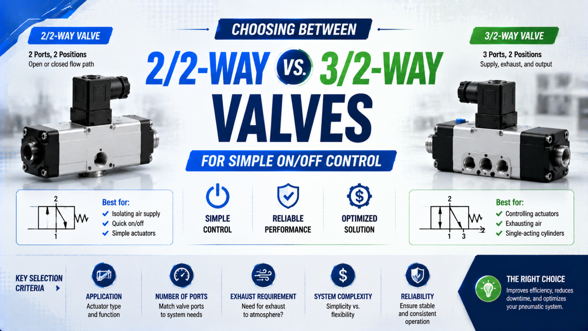
Choose a 2/2-way valve when the circuit needs one controlled flow path that opens or closes. Choose a 3/2-way valve when one work port must alternate between a pressure or vacuum source and a third port used for exhaust, venting, or another defined connection.
That answer covers the valve function, but not the complete selection. A closed 2/2 valve stops its controlled flow path; it doesn’t guarantee that downstream pressure will remain unchanged. A 3/2 valve can pressurize and vent a single-acting actuator, yet its normal state must still match the actuator’s spring direction, load, and required response after power loss.
Key Takeaways
- The first number counts ports; the second counts valve positions.
- Use 2/2 for one controlled flow path with no built-in alternate path.
- Use 3/2 when one work port must switch between supply and exhaust.
- NC and NO describe valve flow paths, not the machine’s safe state.
- Compare working and exhaust flow ratings, not thread size alone.
Short Answer: Choose by the Required Flow Paths
Two questions resolve the first selection step: must the valve control only one path, or must the work port connect to two different paths? ISO 1219-1 provides the rules for fluid-power graphical symbols, while current SMC catalogs show separate 2-port and 3-port valve families with NC and NO variants (ISO 1219-1, SMC VX2, SMC V100).
Use this decision table before comparing coils, thread sizes, or prices:
| Required circuit function | Usual starting choice | What to verify next |
|---|---|---|
| Open or close one supply, gas, liquid, or vacuum path | 2/2 | Flow direction, leakage, pressure differential, medium and seal compatibility |
| Pressurize one actuator port, then vent it | 3/2 | NC/NO state, actuator spring direction, exhaust flow and backpressure |
| Apply and release a pneumatic pilot signal | 3/2 | Pilot pressure range, vent path and response time |
| Connect a work port alternately to two lines | 3/2 or application-specific selector valve | Permitted porting, medium destination and cross-port leakage |
| Control both chambers of a double-acting cylinder | 4/2, 5/2, or a designed two-valve circuit | Separate work-port flow, exhaust treatment and failure state |
| Isolate hazardous pneumatic energy for servicing | Safety-rated isolation arrangement, often with dump capability | Lockability, residual-energy release, reaccumulation and verification |
The phrase “usual starting choice” is deliberate. A 2/2 supply valve plus a separate exhaust valve can control a single-acting actuator. Two 3/2 valves can control the two chambers of a double-acting cylinder. Those circuits may be intentional, but they need an actual schematic and failure review rather than a shortcut based on port count.
For the wider valve-family comparison, use the pneumatic solenoid valve operating guide. This article stays focused on the narrower 2/2 versus 3/2 decision.
What Do 2/2 and 3/2 Actually Mean?
The notation contains exactly 2 numbers: the first gives the number of working fluid ports, and the second gives the number of switching positions represented by the directional-valve symbol. ISO 1219-1 governs symbol construction; ISO 5599-1 does not, because ISO 5599-1 covers mounting interfaces for five-port pneumatic directional valves (ISO 1219-1, ISO 5599-1).
A 2/2-way valve is a two-port, two-position valve. In one position its controlled path is open; in the other it is blocked. The valve has no third port through which the downstream line can be actively vented.
A 3/2-way valve is a three-port, two-position valve. A common pneumatic arrangement uses one supply port, one work port, and one exhaust port. One position connects supply to the work port. The other blocks supply and connects the work port to exhaust.
Read the symbol one position at a time
Each square in a directional-valve symbol represents one position. Lines and arrows show connected paths; capped ends show blocked ports. The spring symbol normally identifies the returned or rest position of a monostable valve. The actuation symbol identifies how the valve moves to its other position.
Don’t infer the flow paths from the product name alone. Check the complete symbol printed on the body or datasheet and confirm the port markings. Manufacturers may use port numbers such as 1, 2, and 3, or letters such as P, A, and R. Their locations are not interchangeable simply because the thread sizes match.
Typical monostable flow states
| Valve function | Rest state | Actuated state |
|---|---|---|
| 2/2 normally closed | Controlled path blocked | Controlled path open |
| 2/2 normally open | Controlled path open | Controlled path blocked |
| 3/2 normally closed | Supply blocked; work connected to exhaust | Supply connected to work; exhaust blocked |
| 3/2 normally open | Supply connected to work; exhaust blocked | Supply blocked; work connected to exhaust |
These descriptions assume conventional supply, work, and exhaust connections and a defined spring-return position. A universally ported 3-way valve may support another approved connection arrangement. That does not create a “mid-position”; a 3/2 valve still has two positions.
When Is a 2/2-Way Valve the Better Choice?
A 2/2 valve controls 1 flow path without providing a second destination for the downstream port. SMC’s current VX2 catalog includes both normally closed and normally open direct-operated 2-port valves, illustrating that port count and normal state are separate selection fields (SMC VX2 catalog).
Typical uses include:
- Starting and stopping a compressed-air supply where no built-in downstream vent is required
- Controlling water, coolant, inert gas, or another compatible medium
- Opening or closing a vacuum-source line when vacuum release is handled elsewhere
- Selecting a default-open cooling or purge path with a normally open valve
- Isolating a test branch during normal production operation
The words “compatible medium” matter. A valve sold for compressed air isn’t automatically approved for oxygen, fuel gas, steam, aggressive chemicals, vacuum, or high-purity service. Check body, seat, seal, lubricant, contamination, pressure, temperature, leakage, and regulatory requirements for the actual medium.
Closing a 2/2 valve does not guarantee pressure retention
When a 2/2 valve closes, it stops the controlled path according to its leakage specification. It doesn’t actively exhaust the downstream line, but pressure may still fall through internal seat leakage, fittings, tubing, downstream components, actuator seals, or intentional consumption.
In our experience, “must retain pressure” is too vague for an RFQ. Replace it with a measurable requirement: permitted pressure decay, test volume, starting pressure, test duration, medium temperature, and acceptable external leakage. If the load must remain safely supported, compressed air alone is not a dependable mechanical holding method.
Flow direction and pressure differential can change the result
Some 2/2 valves are intended for one flow direction. Others permit bidirectional flow but have different leakage or pressure limits in reverse. Pilot-operated designs may need a minimum pressure differential to open or close correctly, while direct-acting designs behave differently at zero differential.
Check maximum operating pressure differential, minimum operating pressure differential, backpressure allowance, vacuum suitability, and mounting orientation. A valve that opens on a bench supply may fail to switch in a low-pressure or reverse-pressure production circuit.
When Is a 3/2-Way Valve the Better Choice?
A conventional 3/2 valve manages 3 ports in 2 positions, so one work port can alternate between supply and exhaust. Current SMC 3-port catalogs list both normally closed and normally open versions, confirming that the required rest-state flow path must be ordered rather than assumed (SMC V100).
The common applications are:
- Supplying and exhausting a single-acting cylinder
- Applying and releasing the pilot signal of a larger valve
- Switching a spring-return diaphragm or rotary actuator
- Connecting a vacuum cup alternately to vacuum and a release line
- Selecting between two approved lines with a universally ported 3-way design
For a spring-return cylinder, the valve must vent the working chamber quickly enough for the spring and external load to complete the return stroke. A 3/2 valve integrates that exhaust path. A 2/2 supply valve can still work if a separate, intentional exhaust device performs the second function.
A 3/2 valve does not always exhaust directly to atmosphere
The third port may connect to a silencer, a piped exhaust header, a controlled vent, a vacuum-release line, or another destination permitted by the valve design. Hazardous, contaminated, wet, or valuable media may require collection rather than atmospheric discharge.
Exhaust accessories change performance. We’ve found that an undersized tube, long exhaust header, restrictive fitting, or clogged silencer can raise backpressure enough to slow the spring return. The silencer-clogging failure guide explains why an actuator may become slow even though the valve still changes state.
Where the actuator needs very fast local venting, a separate quick-exhaust valve may be useful. It should be selected as part of the circuit, not treated as proof that the upstream 2/2 or 3/2 valve is large enough. See the quick-exhaust valve physics guide for that separate decision.
How Do NC, NO, and the Actuator Spring Define the Normal State?
Two normal-state labels, NC and NO, describe the valve’s unactuated flow path, not the final machine motion. SMC’s 2-port and 3-port catalogs offer both labels, while ISO 13849-1:2023 requires safety-related control functions to be designed and integrated from the required machine-level function rather than a component label alone (SMC VX2, ISO 13849-1).
For a monostable solenoid valve, “normal” usually means de-energized and returned by the spring. For a manually or pneumatically actuated valve, it means the unactuated returned state shown by the symbol. A bistable or double-solenoid valve may remain in its last commanded position, so NC or NO language may not describe its loss-of-power behavior.
Determine failure behavior from the complete circuit
Work through these questions:
- Which valve paths are connected with the actuator removed?
- Is the actuator spring-to-retract or spring-to-extend?
- What do gravity and the process load do when pressure disappears?
- Can trapped pressure delay the spring motion?
- Can pressure reappear through another branch, check valve, accumulator, or shared exhaust?
- Does the actuator need to move, stop, or remain mechanically restrained after a fault?
A 3/2 NC valve often allows a spring-retract cylinder to retract when the coil loses power. It does not make “retract” inherently safe. A spring-extend actuator connected to the same valve may extend. A suspended load may fall, and a jammed mechanism may not reach either state.
If the valve participates in a safety function, define the required safety function and performance level first. Then validate the complete safety-related control system, diagnostics, fault response, pneumatic architecture, and mechanical risk controls under the applicable machinery standard.
Why Can Two Valves With the Same Port Size Perform Differently?
ISO 6358 contains 3 parts covering pneumatic flow-rate characteristics and system calculations, while a thread designation describes only the connection. The standard’s scope is why two valves with the same G1/4 or 1/4 NPT ports can deliver different working and exhaust flows (ISO 6358-1, ISO 6358-3).
Compare these fields for the exact model:
| Selection field | Why it matters |
|---|---|
| Rated medium and temperature | Determines seal, lubricant and body compatibility |
| Operating pressure range | Confirms the valve can switch at minimum and maximum pressure |
| Minimum pressure differential | Identifies pilot-operated valves that may not work near zero differential |
| Working-path flow rating | Affects filling time and actuator motion |
| Exhaust-path flow rating | Affects depressurization and spring-return speed |
| Internal and external leakage | Affects pressure retention, vacuum holding and energy use |
| Response time and switching frequency | Affects command timing and thermal duty |
| Coil voltage and tolerance | Prevents weak pull-in, overheating and nuisance switching |
| Port and manifold interface | Prevents incorrect galleries, blocked exhausts and mounting leaks |
| Environmental rating | Covers ingress, vibration, hazardous location and washdown needs |
Port size can hide a smaller internal orifice, pilot passage, molded elbow, sub-base gallery, or exhaust restriction. The port-size versus internal-orifice guide shows why a large thread doesn’t establish flow capacity.
Compare both supply and exhaust paths
For a 3/2 valve, record the P-to-A and A-to-R flow data separately when the manufacturer provides them. A valve may fill the actuator quickly but exhaust it slowly, or the reverse. A silencer and exhaust tube must be included in the installed-path review.
For actuator timing, move beyond a generic “high flow” claim. Use the required pressure, cylinder volume, load, tubing, fittings, valve flow characteristic, and acceptable stroke time. The flow-versus-pressure valve sizing guide covers that next step. If Cv is the published comparison value, the Cv Flow Calculator can support a model-specific check after the circuit function is settled.
Safety Isolation Is Not the Same as Routine On/Off Control
OSHA 29 CFR 1910.147 requires potentially hazardous stored or residual energy to be relieved, disconnected, restrained, or otherwise rendered safe after lockout or tagout. Its definition also excludes control-circuit devices such as push buttons from being energy-isolating devices (OSHA 1910.147).
A normal solenoid 2/2 valve may be suitable for production flow control, but it should not automatically be labeled a lockout valve. Closing it can leave downstream pressure stored. Coil de-energization can also be a control action rather than physical energy isolation.
A lockable manual isolation-and-dump assembly may use a 3/2 function so closing the supply also vents the downstream circuit. Even then, the complete energy-control procedure must address:
- Correct isolation point
- Device lockability
- Downstream residual pressure
- Pressure trapped between check valves or actuators
- Gravity, springs and mechanically stored energy
- Possible pressure reaccumulation
- Verification before work begins
ISO 4414:2010 addresses significant hazards in pneumatic fluid-power systems used on machinery, while OSHA requirements depend on jurisdiction and work activity (ISO 4414). The machine’s risk assessment, local law, and documented energy-control procedure take priority over a generic valve-selection table.
Selection Examples and Common Exceptions
Five common circuits show why the exhaust requirement must be stated explicitly instead of inferred from the words “on/off control.” These examples use the normal functional behavior documented in current 2-port and 3-port valve catalogs, but the final choice still depends on the exact product data.
Compressed-air branch used during production
Use a 2/2 valve when the goal is to open or close the branch without intentionally venting it. Specify acceptable leakage and pressure decay. If personnel will service the isolated equipment, use the site’s approved energy-isolation and residual-pressure-release arrangement instead.
Single-acting spring-return cylinder
A 3/2 valve is usually the simplest solution because it fills and vents the same working port. Match NC or NO to the required rest flow path and the cylinder’s spring direction. Check A-to-R exhaust capacity, silencer backpressure, and the force available throughout the spring stroke.
Vacuum cup
A 2/2 valve can interrupt the vacuum source, but the cup may remain attached until leakage admits air. Use a 3/2 arrangement when the cup must connect to a defined release path. Fast release or blow-off may require another valve and carefully limited positive pressure.
Pneumatic pilot signal
Use a 3/2 valve when the pilot chamber must be pressurized and then positively vented. A 2/2 supply valve alone may leave the pilot trapped, delaying the main valve’s return. Confirm the pilot valve’s minimum pressure, pilot volume, vent restriction, and required response.
Double-acting cylinder
One 3/2 valve does not normally provide full extend-and-retract control for both chambers. Use a 4/2 or 5/2 valve, or a deliberately designed pair of 3/2 valves. The existing 3/2 versus 5/2 comparison and 4/2 versus 5/2 guide cover those architectures.
Which Specifications Belong in the RFQ?
Ten RFQ fields prevent most function mismatches: circuit paths, normal state, actuation, medium, pressure, flow, leakage, electrical data, interface, and environmental conditions. ISO 6358 supplies the flow-characteristic framework, while model catalogs show why NC/NO and pressure limits must be tied to an exact part number (ISO 6358-1, SMC VX31).
Send suppliers this information:
- Required connections in every valve position
- Rest state and required behavior after loss of electrical and pneumatic power
- Solenoid, manual, mechanical, or pneumatic actuation and return method
- Medium, contamination level, lubrication, and temperature range
- Minimum supply, maximum supply, downstream pressure, backpressure, and vacuum conditions
- Required working-path and exhaust-path flow or target actuator time
- Maximum permitted internal and external leakage
- Coil voltage, frequency for AC coils, tolerance, connector, power and duty cycle
- Port thread, flow direction, manifold interface, mounting position and envelope
- Ingress, washdown, vibration, hazardous-location and material requirements
For a replacement, include the complete old part number, a clear photograph of the symbol and port markings, coil label, manifold interface, and circuit schematic. The OEM solenoid-valve compatibility guide explains why matching voltage and thread alone is not enough.
Ask the supplier to identify any minimum pressure differential, prohibited reverse pressure, separate exhaust-flow rating, allowed silencer, manual override behavior, and limitations on universal porting. Put those restrictions into the approved parts record rather than leaving them in an email.
2/2-Way and 3/2-Way Valve FAQs: What Should Buyers Ask?
Five questions cover the most common selection gaps: alternate exhaust paths, pressure retention, exhaust destination, normal-state behavior, and double-acting control. These distinctions follow ISO 1219 symbol logic, current SMC 2-port and 3-port catalogs, and the residual-energy boundary in OSHA 1910.147.
Can a 2/2-way valve control a single-acting cylinder?
Yes, but only if the working chamber has a separate, intentional exhaust path. A 2/2 supply valve by itself opens or blocks one path and cannot actively vent the cylinder port. A 3/2 valve is usually simpler because it integrates the supply and exhaust functions in one component.
Does a closed 2/2-way valve hold downstream pressure?
It blocks the controlled flow path within its leakage specification, but it does not guarantee constant downstream pressure. Pressure can decay through the valve seat, tubing, fittings, actuator seals, or downstream consumption. Specify an allowable pressure-decay test if short-term retention is an actual process requirement.
Does the third port of a 3/2-way valve always exhaust to atmosphere?
No. Depending on the approved valve function and medium, the third port may connect to a silencer, piped exhaust, controlled vent, vacuum-release line, or another defined destination. Never discharge a hazardous or valuable medium without checking the valve documentation, process requirements, and applicable safety rules.
Should I choose a normally closed or normally open 3/2-way valve?
Choose from the required rest flow path and complete machine behavior. Check whether the actuator is spring-to-retract or spring-to-extend, what the load does without pressure, and whether trapped pressure delays motion. NC or NO describes the valve path; it does not certify a safe machine state.
Can one 3/2-way valve control a double-acting cylinder?
One conventional 3/2 valve controls only one work port, so it does not provide normal bidirectional control of both cylinder chambers. Use a 4/2 or 5/2 valve, or an intentionally designed pair of 3/2 valves when independent chamber control and the resulting failure modes are acceptable.
Sources and technical references
- ISO 1219-1:2012, fluid-power graphical symbols
- ISO 6358-1:2013, pneumatic flow-rate characteristics
- ISO 4414:2010, pneumatic-system safety requirements
- ISO 13849-1:2023, safety-related control systems
- OSHA 29 CFR 1910.147, control of hazardous energy
- SMC VX2 direct-operated 2-port solenoid valve catalog
- SMC V100 direct-operated 3-port solenoid valve catalog