

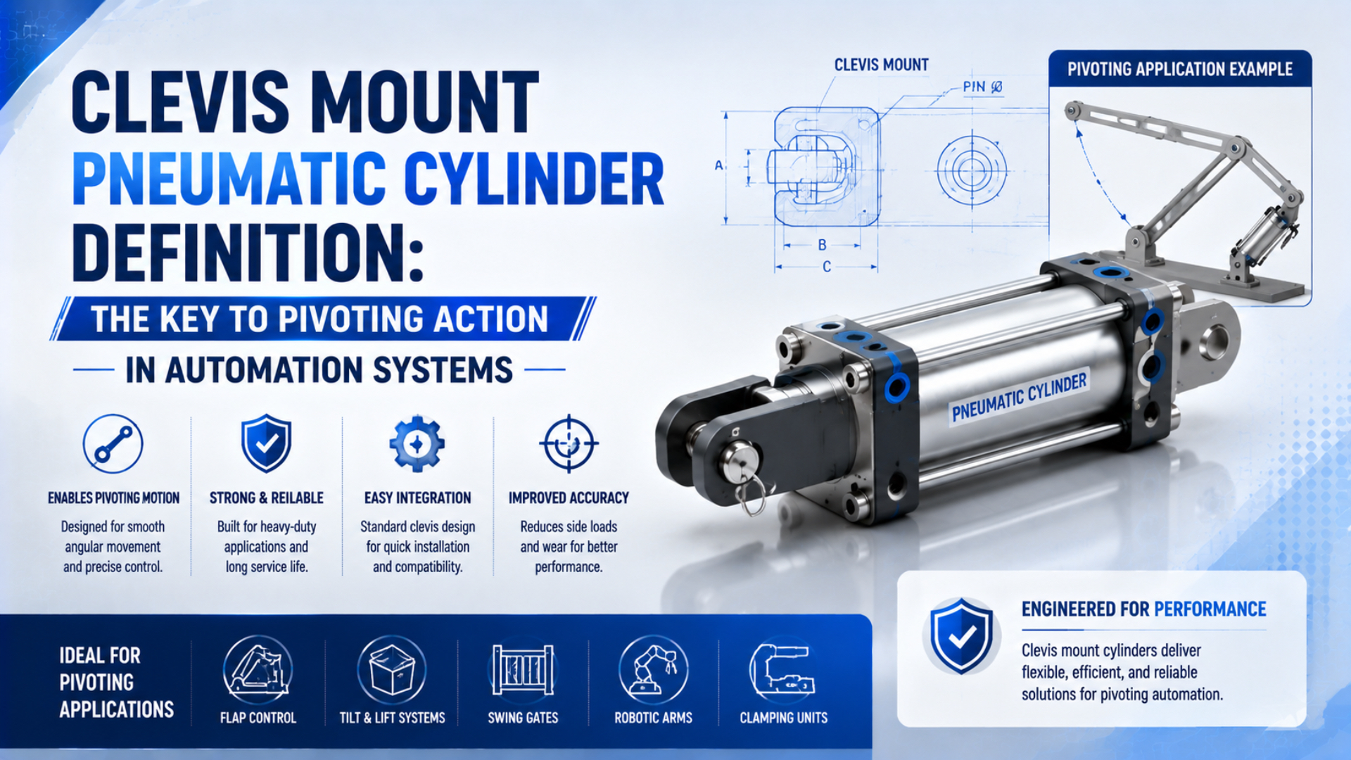
A clevis mount pneumatic cylinder is a linear actuator connected to a machine by a pin joint so the cylinder can rotate about one defined axis. It suits a lever, gate, chute, or linkage whose connection point follows an arc in one plane. This mounting arrangement does not make the piston rod a guide, nor does it correct unrestricted multi-axis misalignment.
That distinction matters. Whether a clevis fits the cylinder is only the first question. Designers must confirm that the rear and rod-end pivots describe the same motion plane, their pin axes remain parallel, and the cylinder can swing through its complete working arc without interference. For context, the broader cylinder mounting selection guide places that geometry within the other fixed and pivot-mount families.
Key Takeaways
- One clevis pin provides 1 rotational axis.
- ISO 8140:2018 standardizes interchangeable rod-end clevis dimensions for pneumatic cylinder series rated to 10 bar.
- Safe operation still depends on parallel pivot pins, a suitable joint at each end, supported hardware, external load guidance, and verified clearance through every stroke position.
Technical basis: this article uses ISO dimensional standards and manufacturer mounting instructions, not generic replacement claims. Author information is available on the Jack Chen author page, and publisher information is available on the About Us page.
What Is a Clevis Mount Pneumatic Cylinder?
Published in 2018, ISO 8140 covers rod-end clevises designed for pneumatic-cylinder series rated up to 1,000 kPa, or 10 bar. In practical machine terms, a clevis mount pneumatic cylinder is a cylinder with a pinned body mount, a pinned rod-end connection, or both, arranged to transmit axial cylinder force while the assembly changes angle in one plane (ISO 8140:2018).
Typical clevis geometry uses a forked yoke with two aligned holes. Between the fork arms sits a matching lug or eye, with a pin passing through all three members. That pin defines the pivot axis. Depending on the cylinder series, the body-side pivot may be an integral rear clevis, a detachable cap clevis, or a single-lug eye used with an external bracket.
Moving-end terminology needs equal precision. A rod-end clevis is a forked accessory that threads onto the piston rod and accepts a pin. By contrast, a rod eye has a single hole rather than a fork. Adding a spherical bearing creates a spherical rod eye that can accommodate a catalog-defined amount of tilting movement. These accessories are not interchangeable merely because their threads appear similar.
For detachable-mount cylinders, ISO 15552 establishes basic, mounting, and accessory dimensions for bores from 32 mm to 320 mm at a maximum rated pressure of 10 bar. It supports dimensional interchangeability within its scope, but it does not certify the geometry, loads, or safety of a completed linkage (ISO 15552:2018).
Functionally, a clevis is a single-axis force-transfer joint. It releases the one rotational degree of freedom required by a planned arc while the pin, lugs, brackets, guide, and frame carry the resulting reactions.
The Two-Pivot Geometry Behind a Clevis Installation
Parker gives 3 conditions for clevis-mounted cylinders: pivot the cylinder at both ends, keep the pivot-pin centerlines parallel, and confirm free swing through the full working arc. Meeting only the first condition is not enough. A rear clevis can still bind the rod if the rod end is rigid, offset, or rotating about a different axis (Parker Cylinder Safety Guide).
Think of the mechanism as a four-part load path:
- Clevis lets the cylinder rotate.
- Frame bracket supports the body-side pin without twisting.
- Piston and rod transmit axial force along the cylinder centerline.
- Rod-end clevis or eye transfers that force to the moving lever while preserving the articulation needed at every position in the working arc.
Both pins are normally perpendicular to the intended motion plane. Viewed from the side, they appear as two pivot points. Viewed along either pin, their axes should be parallel. If one bracket is twisted, the mechanism asks the clevis forks, pin clearance, rod bearing, or spherical element to absorb an out-of-plane error that the joint was not selected to carry.
This drawing also explains why a clevis does not “absorb side load.” Correct geometry avoids imposing an unnecessary side reaction. It does not provide an external bearing for the payload. If the load can translate laterally or generate pitch, yaw, or roll moment, use a separate guide and verify its ratings. Detailed checks appear in the side-load mitigation guide.
When Should You Choose a Clevis Mount?
Choose a clevis as the starting point when the driven connection follows 1 predictable arc and the cylinder must change angle during its stroke. Parker classifies fixed clevis arrangements for a curved rod path in one plane. Selection becomes unsafe when the mechanism has compound motion, an uncontrolled lateral load, or no clear pivot center (Parker Pneumatic Actuator Products).
Good application signals include:
- A known shaft controls the lever arc.
- Rear and rod-end pivots can share parallel pin axes.
- Rigid frame support carries the body-pivot bracket without measurable twist.
- The rod-end joint retains articulation clearance at retracted, mid-stroke, and extended positions.
- Hoses, sensors, fittings, guards, pin retainers, and nearby machine parts remain outside the complete swept envelope, including the space needed for maintenance access and tolerance stack-up.
Do not use a clevis to compensate for a worn or misaligned guide on a load that should move linearly. Restoring the guide and centerline is the first job. Adding pin clearance may temporarily hide the symptom while increasing impact, pin wear, and position variation.
Do not select a clevis simply because the mounting structure flexes. Frame movement changes the pivot locations under load and can force the cylinder into a different plane. Measure or calculate loaded bracket deflection, then stiffen or relocate the support as required.
An overhung payload remains unsuitable for an unsupported piston rod even when a clevis is fitted. Rod duty should remain axial. Rails, bushings, guided cylinders, or rated guided rodless actuators should carry lateral force and moments. For a broader acceptance process, use the mounting and alignment workflow.
Clevis, Spherical Eye, Trunnion, or Fixed Mount?
Within the same 10 bar family, ISO separates two rod-end accessory functions: ISO 8140 covers clevises for mechanically transmitting force, while ISO 8139 covers spherical eyes for oscillatory rotation and tilting. That does not make a spherical eye a universal joint. Its permissible articulation and load still come from the exact product catalog (ISO 8139:2018).
| Motion and support condition | Suitable starting point | Main boundary |
|---|---|---|
| Arc in one defined plane, body pivot at the rear | Rear or cap clevis plus a pivoting rod end | Pin axes must remain parallel |
| Arc in one plane, body pivot needed near the middle | Trunnion plus a pivoting rod end | Bearing blocks must be coaxial and pins supported |
| Limited catalog-rated tilting at the rod end | Spherical rod eye with a compatible body pivot | Stay within angular and load ratings |
| Straight, guided translation | Centerline fixed flange or another catalog-approved fixed mount | Load and guide must remain coaxial |
| Lateral force or overturning moment at the payload | External guide plus an appropriate cylinder mount | The guide, not the piston rod, carries the moment |
Moving the body pivot from the cap to a defined position on the cylinder creates a trunnion arrangement. That changes the swing envelope, support reactions, cylinder balance, and sometimes rod-stability check. It does not provide multi-axis freedom. The trunnion mount application guide covers those differences without duplicating them here.
“Double clevis” is also easy to misunderstand. Two clevises create two pivot joints, but both still rotate about parallel axes. Together they let the cylinder follow the linkage arc. This arrangement does not create independent rotation about two perpendicular axes.
Load and Hardware Checks Before Selection
Parker’s pivot-transfer data gives an effective-thrust factor of 0.707 when a cylinder acts at 45 degrees to the driven lever. That value shows why bore force alone cannot define lever output. The installation review must include the changing force angle, pin and lug reactions, rod stability, bracket stiffness, and the mechanism’s worst position (Parker Pneumatic Actuator Products).
Axial cylinder thrust is not reduced by the clevis itself. Instead, the joint changes how that thrust enters a rotating mechanism. Useful force at the lever depends on the instantaneous angle, so the minimum useful output may occur at a different stroke position from the maximum cylinder force.
Check the following elements as one rated chain:
Cylinder and piston rod
Confirm bore, rod diameter, pressure, stroke, push or pull duty, cushioning, speed, and mounting orientation. Long strokes under compression need a buckling review because a rear pivot does not brace the rod. The cylinder force guide establishes available axial thrust; the configured cylinder catalog remains the controlling source.
Clevis pin and retention
Use the pin diameter, material, fit, and retention method specified for the accessory and cylinder series. Check shear, bearing pressure, wear surface, corrosion protection, lubrication requirements, and whether the pin is supported in single or double shear. Retaining rings and cotter pins keep the pin in place; they do not upgrade its load rating.
Clevis forks, lug, and machine bracket
Verify fork thickness, lug thickness, hole diameter, edge distance, welds, fasteners, and bracket stiffness. Excessive clearance produces impact and position variation. Insufficient clearance can clamp the lug between the fork arms and prevent free rotation.
Working arc and interference envelope
Model or measure the cylinder at the retracted, mid-stroke, and extended positions. Include fittings, flow controls, sensors, cable connectors, hose bend radius, guards, pin-retention hardware, and maintenance access. Endpoint clearance alone is insufficient because a collision can occur midway through the arc.
Joint alignment and articulation
Specify the two pivot locations from a common machine datum. Confirm that the pin axes are parallel and that the clevis does not bottom against the lug or bracket at any point. If a spherical eye is used, preserve articulation margin on both sides rather than operating against its angular stop.
How Should a Clevis-Mounted Cylinder Be Installed and Commissioned?
Parker’s clevis instruction contains 3 acceptance checks before normal operation: pivot both ends, keep the pin centerlines parallel, and verify unobstructed swing through the working arc. Commissioning should prove those conditions first without pressure, then at reduced pressure and speed, before production load is applied (Parker Cylinder Safety Guide).
Before anyone enters the hazard zone, isolate electrical, pneumatic, gravitational, and other stored energy using the machine’s validated procedure. OSHA 29 CFR 1910.147 covers servicing where unexpected startup or release of stored energy could cause injury (OSHA 1910.147).
Use this commissioning sequence:
-
Confirm the safe state. Lock out energy, exhaust stored air, block suspended loads, and verify isolation.
-
Check bracket datums. Measure both pivot centers and pin-axis parallelism.
-
Assemble without forcing alignment. Fasteners should secure correctly positioned parts. They must not pull a twisted or offset bracket into place.
-
Move the mechanism manually. Where the machine design permits, sweep from retracted to extended without pressure. Pause at mid-stroke and any minimum-clearance position to feel for binding, joint bottoming, hose tension, or contact.
-
Inspect the envelope. Check the body, rod, fittings, hoses, sensors, guards, and pin retainers.
-
Pressurize gradually. Start at reduced pressure and low speed while observing from a safe position. Stop if the cylinder hesitates, a bracket moves, a hose tightens, or joint clearance disappears.
-
Verify under production load. Record pressure, stroke time, endpoint position, bracket movement, unusual noise, and wear indicators.
-
Set the inspection baseline. Record new-pin diameter, hole or bushing clearance, lubrication condition, retainer position, and photographs. These readings give maintenance a numerical reference for detecting uneven or accelerating wear rather than relying on visual judgment alone.
Inspection frequency should follow the manufacturer, duty cycle, shock level, contamination, corrosion exposure, and measured wear trend. Replace pins and bushings against documented limits. Calendar intervals alone are not a substitute for an application-specific maintenance plan.
Clevis-Mount Cylinder RFQ Checklist
Although ISO 15552 covers bores from 32 mm to 320 mm, matching that dimensional family alone does not prove interchangeability of a complete clevis installation. An RFQ should identify the exact cylinder series and accessory part numbers, then describe the two pivot datums, force direction, arc, pin support, environment, and acceptance test (ISO 15552:2018).
Organize the RFQ around four interfaces:
| RFQ group | Information to provide |
|---|---|
| Cylinder identity | Existing manufacturer, complete part number, drawing revision, applicable standard, bore, rod diameter, stroke, pressure range, speed, cycle rate, cushioning, ports, sensors, and thread forms |
| Pivot geometry | Rear mount and rod-end accessory codes, both pivot-center coordinates from one datum, minimum and maximum included angle, bracket width, lug thickness, fork clearance, and any required spherical articulation |
| Loads and hardware | Push, pull, or reversing cylinder load; pin diameters, usable lengths, fits, materials, bushings, retention, bracket construction, and external guide arrangement |
| Installation and acceptance | Hose and fitting orientation through the swept envelope, temperature, water, washdown, dust, corrosion, lubrication, manual-travel check, reduced-speed trial, loaded-motion test, and dimensional acceptance criteria |
Replacement reviews should compare drawings rather than stop at bore, stroke, and port size. Pivot-center distance, overall retracted length, thread engagement, accessory width, pin diameter, and fitting envelope can differ even between nominally similar cylinders. The ISO-cylinder replacement workflow shows how to document those interfaces before ordering.
Clevis Mount Pneumatic Cylinder FAQs
Confirmed in 2024, ISO 8140:2018 is the 4th edition of the rod-end clevis dimensional standard for pneumatic cylinders. The questions below separate that interchangeability scope from the geometry, load, and maintenance decisions that remain the machine designer’s responsibility (ISO 8140:2018).
Does a clevis mount eliminate side loading?
No. A correctly arranged clevis lets the cylinder follow a planned arc instead of forcing a rigid body mount to resist that rotation. Side loading can still result from nonparallel pins, a twisted bracket, worn clearance, an unguided payload, frame deflection, interference, or a rod-end joint that reaches its articulation limit.
Must a clevis-mounted cylinder pivot at both ends?
Yes, when the rod-end connection follows an arc. Parker instructs that clevis-mounted cylinders should pivot at both ends with the pin centerlines parallel. A rigid rod-end connection can over-constrain the linkage even when the rear mount pivots freely, so both joints and the complete travel need to be checked together.
Can a clevis cylinder replace a foot-mounted cylinder?
Only after redesigning and verifying the mounting geometry. The conversion changes the rear reaction point, machine bracket, rod-end connection, swing envelope, hose movement, and often the retracted installation length. Matching bore, stroke, pressure, and ports does not prove that the replacement fits or carries the same installed loads.
When should a spherical rod eye be used instead?
Use a spherical rod eye when the mechanism requires limited tilting movement that the exact accessory permits. ISO 8139 covers interchangeable dimensions for 10 bar series spherical eyes, but the configured manufacturer’s angular and load ratings still control. It should not be used to conceal an undefined three-dimensional path or missing external guide.
What clevis wear should maintenance inspect?
Inspect pin diameter, bushing or hole clearance, uneven contact, fretting, corrosion, lubrication, fork spreading, lug deformation, retainer condition, bracket movement, and rod alignment through the stroke. Compare readings with the new-installation baseline and product limits. A fixed calendar interval without duty and environment data can miss rapid wear or cause unnecessary replacement.
Sources and technical references
- ISO 8140:2018, Mounting dimensions of rod-end clevises, retrieved 2026-07-26.
- ISO 15552:2018, Basic, mounting and accessories dimensions, retrieved 2026-07-26.
- ISO 8139:2018, Mounting dimensions of rod-end spherical eyes, retrieved 2026-07-26.
- Parker Pneumatic Actuator Products, retrieved 2026-07-26.
- Parker Safety Guide for Selecting and Using Hydraulic, Pneumatic Cylinders and Their Accessories, retrieved 2026-07-26.
- OSHA 29 CFR 1910.147, The control of hazardous energy, retrieved 2026-07-26.