

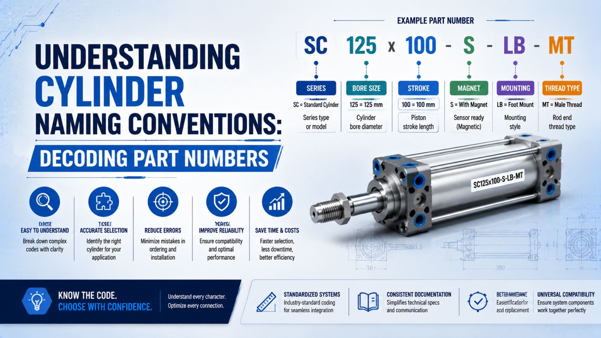
Pneumatic cylinder part numbers are manufacturer-specific ordering codes, not a universal engineering language. A code may identify the product family, bore, stroke, guide, cushioning, sensing, thread, or mounting option. The sequence and meaning can change between brands, between series from the same brand, and between catalog revisions.
The safe method has four steps. Copy the complete code. Locate the exact manufacturer’s ordering table. Decode each position in sequence. Finally, verify the result against the configured drawing and application. If the catalog doesn’t define a character, don’t guess. A plausible interpretation is still an unverified interpretation. That is the core rule.
Key Takeaways
- ISO 15552 covers detachable-mount cylinders from 32 to 320 mm bore at 10 bar.
- Decode codes only with the exact manufacturer’s ordering table.
- Bore and stroke don’t prove port, sensor, cushion, or mounting compatibility.
- Release a replacement from drawings and tests, not a cross-reference line.
In this guide
- What Can a Cylinder Part Number Tell You?
- How Should You Decode a Pneumatic Cylinder Part Number?
- Manufacturer-Specific Festo DGCI Codes
- SMC MY and CY: Two Different Rodless Mechanisms
- How Should Parker OSP-P Numbers Be Read?
- Why Do Suffix and Port Codes Fail Across Brands?
- ISO Standards Define Interfaces, Not Model Codes
- How Do You Verify a Replacement After Decoding the Code?
- What If the Nameplate Is Incomplete or Unreadable?
- Cylinder Part Number FAQs
What Can a Cylinder Part Number Tell You?
SMC’s product record for MY1B16-300 identifies a 16 mm bore, 300 mm stroke, basic mechanically jointed rodless design, thread selection, and auto-switch configuration. That useful detail comes from one exact series record, not from treating every letter or number as a cross-brand code (SMC Web Catalog).
A complete part number can be a compact configuration record. The catch is that the manufacturer owns the syntax. Before decoding, separate what the code explicitly proves from what still needs a drawing, datasheet, photo, or test.
| Information | Sometimes encoded directly | Still requires verification |
|---|---|---|
| Product identity | Brand, family, series, generation | Current status, successor, catalog revision |
| Main dimensions | Bore and stroke in many series | Overall length, mounting centers, carriage height |
| Pneumatic interface | Thread option or port arrangement in some series | Exact thread standard, port size, location, access |
| Motion features | Cushion, guide, brake, or lock option | Energy capacity, adjustment range, dynamic behavior |
| Sensing | Magnet or switch provision | Switch model, logic, connector, cable exit, trip position |
| Materials | Seal or corrosion option in some codes | Full material declaration and environmental suitability |
Can the two largest numbers simply be read as bore and stroke? Sometimes. SMC’s MY1B16-300 supports that reading because its own product record does. A different series may include a nominal frame size, port code, variant number, inch dimension, or five-digit stroke field. Position alone is not evidence.
In my application reviews, I found that treating a decoded part number as an evidence index produces a clearer result. Each token should point to a manufacturer definition, drawing field, or test requirement. If a token points only to an assumption, I mark it unresolved instead of converting it into a specification.
How Should You Decode a Pneumatic Cylinder Part Number?
ISO 6432:2015 covers single-rod pneumatic cylinders from 8 to 25 mm bore at a maximum working pressure of 1,000 kPa, or 10 bar, yet it explicitly leaves manufacturers freedom of design. Even standardized cylinders therefore need their own manufacturer code table (ISO 6432:2015).
Use this sequence whenever you identify an installed cylinder:
-
Record the code exactly. Preserve hyphens, slashes, spaces, leading zeroes, and letter case. Photograph the complete nameplate before cleaning or removing the unit.
-
Confirm the manufacturer. A familiar prefix can appear in another supplier’s code or in an aftermarket reference. Check the logo, label format, product family, and any separate material number.
-
Find the exact series document. Use the manufacturer’s current catalog, archived catalog, product page, or datasheet. Match the product generation and document date when possible.
-
Read positions in order. Don’t split letters into invented meanings. Follow the ordering table’s fields, allowed values, and conditional notes.
-
Separate omitted defaults from unknowns. A blank position may mean the standard option, but only if the ordering table says so.
-
Validate the decode. Compare bore, stroke, ports, overall dimensions, mounting, sensing, cushioning, and operating limits with the installed hardware.
-
Record the evidence. Save the source URL, document title, revision or date, page, decoded value, and unresolved questions.
What if the complete code produces no manufacturer result? Stop searching for a visual resemblance. The unit may be obsolete, incorrectly transcribed, privately labeled, assembled with accessories, or missing a suffix. Move to the incomplete-nameplate workflow rather than forcing the characters into a nearby series.
| Evidence field | Example entry |
|---|---|
| Nameplate text | Exact characters and separators |
| Manufacturer source | Product page or catalog title |
| Document identity | Publication date, revision, or archive year |
| Decoded configuration | Series, bore, stroke, and documented options |
| Drawing check | Critical dimensions and port locations |
| Open question | Unreadable character, missing option, or undocumented change |
This record becomes much more useful than a handwritten cross-reference. Purchasing can reorder the same configuration, engineering can see what was verified, and maintenance can recognize when a later supplier changes an interface.
Manufacturer-Specific Festo DGCI Codes
Festo’s DGCI catalog lists 5 piston diameters, 18, 25, 32, 40, and 63 mm, with strokes from 100 to 2,000 mm. Its type-code table places KF in the guide field and defines it as a recirculating ball bearing guide (Festo DGCI catalog).
Consider this catalog-supported structure:
DGCI - 25 - 300 - KF
| Position | Catalog meaning | What it establishes |
|---|---|---|
| DGCI | Linear drive with displacement encoder | Product family and feedback design |
| 25 | 25 mm piston diameter | Nominal bore |
| 300 | 300 mm stroke | Nominal travel |
| KF | Recirculating ball bearing guide | Guide type |
Notice what isn’t present: PPV-A. Festo uses that cushioning and sensing notation in documented DGC or older DGPL patterns, while the DGCI modular ordering table uses its own field sequence. Combining fragments from those families creates a code that looks convincing but isn’t supported by the DGCI table.
This is why abbreviations can’t be expanded by intuition. DGCI is the series designation given by Festo. It should not be broken into invented definitions such as “double-acting guided” plus “compact ISO.” Likewise, KF is a recirculating ball bearing guide in this DGCI table, not a generic connector code.
If you are replacing a standards-based Festo rod cylinder rather than a DGCI linear drive, use the separate Festo DNC replacement guide. The code families, interfaces, and successor path are different.
SMC MY and CY: Two Different Rodless Mechanisms
SMC separates two rodless mechanisms clearly: MY1 products are mechanically jointed rodless cylinders, while CY3B, CY3R, CY1S, and related CY products are magnetically coupled rodless cylinders. One shared word, “rodless,” does not make their prefixes or load behavior interchangeable (SMC rodless-cylinder manuals).
The verified product example MY1B16-300 can be read as follows:
| Code portion | Verified meaning |
|---|---|
| MY1B | MY1B mechanically jointed rodless cylinder, basic type |
| 16 | 16 mm bore |
| 300 | 300 mm stroke |
SMC’s product record also shows why a short code may hide important defaults. For this exact unit, the catalog record specifies standard piping, the applicable thread choice, no auto switch in the base code, and standard made-to-order status. Those values come from the configured product page. They are not encoded by a universal P, M, or A rule.
Now compare the CY family. SMC identifies CY3B as a magnetically coupled rodless cylinder, basic type, and CY3R as a direct-mount type. A label beginning with CY therefore shouldn’t be classified as a conventional rod cylinder merely because another brand uses a similar letter elsewhere.
Do you need to decode every optional SMC suffix from memory? No. Keep the series catalog open while reading the code. Some options are conditional on bore, piping arrangement, switch selection, quantity, or made-to-order specification. The table, not familiarity, decides which field comes next.
How Should Parker OSP-P Numbers Be Read?
Parker’s OSP-P catalog allows standard rodless-cylinder strokes up to 6,000 mm in 1 mm steps, with longer strokes available on request. The same catalog lists multiple bore-specific series, port sizes, mounting accessories, guides, and brakes, so OSP-P identifies a modular family rather than a universal suffix grammar (Parker OSP-P catalog).
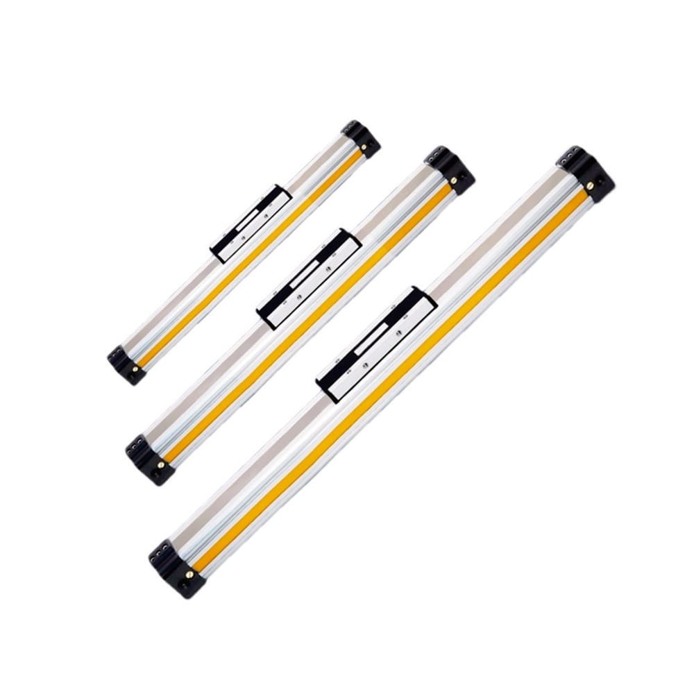
Start with the series designation, such as OSP-P32. Parker’s catalog uses the number as the cylinder series size, then supplies size-specific dimensions and ports. Stroke and options must be read from the ordering instructions for the exact OSP-P configuration. Accessories can also carry independent order numbers.
The practical lesson is restraint. Don’t infer that A, AN, or another suffix must mean the same mounting, carriage, sensor, or cushioning option found in a different catalog. Parker’s own literature uses position-based fields and separate accessory tables. Read the full field sequence, including leading zeroes where the ordering system requires them.
A photograph of the cylinder body is helpful, but it can’t confirm the complete configuration. Record the label, carriage or guide, port orientation, end-cap arrangement, sensors, mountings, and measured stroke. For a modular family, those visible assemblies may matter as much as the base cylinder code.
Why Do Suffix and Port Codes Fail Across Brands?
ISO 228-1 covers parallel pipe threads from 1/16 through 6 inches, while ASME B1.20.1 covers the dimensions and gauging of NPT and several related inch pipe-thread forms. These standards define thread systems. They do not make a single letter in every cylinder part number mean that thread (ISO 228-1; ASME B1.20.1).
This distinction prevents two common mistakes:
| Marking or code | Safe interpretation |
|---|---|
G1/4 in a documented thread field |
ISO 228 parallel pipe thread of the stated size |
R1/4 in a documented thread field |
ISO 7 pipe-thread designation; confirm internal/external mating details |
NPT 1/4 or a defined NPT option |
ASME general-purpose inch pipe thread |
M5, M7, or another M size |
Metric thread only when the product data defines it |
F, FA, B, P, R, or A alone |
Manufacturer-specific token until the ordering table defines it |
The mechanical consequences are real. Parallel pipe threads generally rely on a sealing surface or seal outside the thread, while pressure-tight tapered thread systems use different geometry and sealing practice. Similar nominal sizes can still have different pitch, taper, engagement, and gauge requirements.
Port location is a separate variable. A code may select a front, side, rear, centralized, or alternative connection, but the same letter can mean something else in another family. Compare the configured drawing for thread designation, port size, center location, orientation, fitting envelope, and tool access.
For a deeper comparison, see the BSP, NPT, G, and R thread guide. Use adapters only after pressure rating, sealing method, protrusion, flow area, and installation clearance have been reviewed.
In my application reviews, I found that a port mismatch isn’t always a thread mismatch. A port code has two jobs: it identifies a connection standard and locates that connection on a configured product. Matching the thread without matching its position can still leave the replacement impossible to pipe on the machine.
ISO Standards Define Interfaces, Not Model Codes
ISO 15552:2018 establishes basic, mounting, and accessory dimensions for detachable-mount pneumatic cylinders from 32 to 320 mm bore at a maximum rated pressure of 1,000 kPa, or 10 bar. ISO 6432:2015 covers basic and mounting dimensions for single-rod cylinders from 8 to 25 mm bore (ISO 15552; ISO 6432).
Those standards help define interchangeable mechanical interfaces within their scopes. They do not define one cross-brand part-number language. Nor do they promise that every supplier offers the same:
- port thread and port orientation;
- rod thread or rod-end accessory;
- magnetic piston and sensor system;
- seal material and lubrication policy;
- cushioning method and adjustment access;
- temperature, pressure, speed, or environmental rating;
- special stroke, tandem, through-rod, lock, or anti-rotation option.
Dimensional interchangeability is therefore narrower than functional equivalence. A candidate may bolt into the same mounting pattern yet need different fittings, switches, cable routing, cushion settings, or rod hardware. It may also respond differently at the installed load and speed.
The ISO 15552 interchangeability checklist expands this boundary into four approval layers. For small round cylinders, use the dedicated ISO 6432 replacement workflow.
When the installed cylinder is outside either standard’s scope, the manufacturer drawing becomes even more important. The code may still be decodable, but compatibility must be established interface by interface.
How Do You Verify a Replacement After Decoding the Code?
ISO 10099:2001 specifies functional tests and acceptance criteria for final examination of double-acting, single-rod pneumatic cylinders. That is a different evidence layer from ISO mounting dimensions and from a manufacturer’s part-code table. A replacement decision needs identification, interface comparison, and application acceptance (ISO 10099:2001).
Use this verification matrix after decoding:
| Gate | Verify | Evidence |
|---|---|---|
| Identity | Manufacturer, complete code, series, revision, successor status | Nameplate, official product record, ordering table |
| Mechanical fit | Mounting pattern, overall lengths, rod or carriage interface, clearance | Controlled drawings, measurements, CAD overlay |
| Pneumatic fit | Thread, port location, fitting envelope, pressure limits | Configured drawing and technical data |
| Motion duty | Bore, stroke, force margin, speed, side load, moment, cushioning | Application inputs, catalog limits, calculation record |
| Sensing and control | Magnet, switch type, logic, connector, trip position | Sensor datasheet, wiring, guarded sequence test |
| Environment | Temperature, media, seals, corrosion, washdown, cleanliness | Material and environmental declarations |
| Release | Leakage, travel, timing, sensing, end impact, restart behavior | First-article inspection and machine trial |
Bore and stroke belong in the matrix, but neither should be treated as an automatic “must match” without context. A true drop-in replacement usually preserves them because they affect force, travel, and mounting. A redesign may intentionally change the bore if engineering recalculates force, flow, structure, cushioning, and machine safety.
Use the Cylinder Force Calculator when the decoded bore must be checked against working pressure, rod diameter, friction allowance, and safety factor. The calculator supports the engineering review; it doesn’t prove dimensional fit or catalog equivalence.
For a brand-specific example, the Norgren-to-generic ISO cylinder guide shows how identification, drawing overlays, duty checks, and first-article records work together.
In replacement reviews, I found that the strongest cross-reference is a controlled comparison package, not a database row. Freeze the original code, proposed code, drawings, deviations, acceptance limits, test result, and approved revision. If the supplier later changes a critical feature, the package shows exactly which gate must be reopened.
What If the Nameplate Is Incomplete or Unreadable?
SMC’s MY1B16-300 product record contains at least 6 useful identification fields: series, bore, stroke, thread selection, piping arrangement, and auto-switch configuration. When the nameplate no longer exposes that information, photos and measurements must rebuild the missing evidence before a replacement is selected (SMC Web Catalog).
Collect the following before removing the cylinder:
- every readable character, logo, material number, serial number, and date code;
- clear photos of all sides, ports, end caps, rod or carriage, guides, sensors, and mountings;
- retracted and extended overall length, measured stroke, body size, and rod diameter where applicable;
- mounting-hole spacing, pilot diameters, pin sizes, rod thread, carriage pattern, and center heights;
- port thread, port location, fitting orientation, and available tool clearance;
- sensor model, connector, cable exit, electrical logic, and switching positions;
- machine function, moving mass, direction, working pressure, speed, cycle rate, and environment.
Don’t measure a pressurized or unsupported axis. Isolate the air supply, dissipate stored pressure, secure gravity or suspended loads, and follow the machine’s energy-control procedure before touching the actuator.
When dimensions point to several possible families, compare distinctive interfaces first. End-cap shape and color are weak evidence. Mounting centers, profile geometry, carriage pattern, port arrangement, switch groove, and accessory interfaces are more discriminating.
Mark every inferred value. A measured 300 mm travel isn’t proof that the catalog stroke is exactly 300 mm if the mechanism has external stops or lost motion. Likewise, a thread that accepts a fitting isn’t identified until its diameter, pitch, taper, and sealing method are confirmed.
Cylinder Part Number FAQs
These 5 answers apply the same evidence boundary used by ISO 15552 and ISO 6432. The standards cover defined dimensional series from 8 to 320 mm bore at 10 bar, but manufacturers retain their own product designs, options, and ordering codes. Decode first, then verify the configured interfaces (ISO 15552; ISO 6432).
Can I decode any pneumatic cylinder part number from its numbers alone?
No. Numbers often represent bore and stroke, but they can also represent a frame size, variant, port, inch dimension, or zero-padded stroke field. Confirm the manufacturer and exact series, then follow its ordering table. Treat any unexplained number as unresolved until the product record or drawing defines it.
Does the same bore and stroke guarantee a drop-in replacement?
No. Bore and stroke don’t establish mounting centers, overall length, rod or carriage interface, port thread and position, sensors, cushioning, seals, or application performance. Compare the configured drawings and operating limits, then inspect and test the first article on the machine before releasing repeat orders.
What does PPV-A mean on every Festo cylinder?
It should be interpreted only within the exact Festo family and catalog. In documented DNC and DGC patterns, PPV relates to adjustable pneumatic cushioning and A to position sensing. The DGCI modular table uses a different field sequence, so don’t append or decode PPV-A there by analogy.
Are G1/4, R1/4, and 1/4 NPT interchangeable?
No. G threads follow the ISO 228 parallel-thread system, R designations fall under ISO 7 pressure-tight pipe threads, and NPT is covered by ASME B1.20.1. Their geometry and sealing methods differ. Match the exact designation or use a reviewed adapter with suitable pressure, flow, sealing, and clearance.
What information should I send with a cylinder cross-reference request?
Send the complete part number, nameplate and installation photos, manufacturer datasheet, bore, stroke, mounting dimensions, port details, sensors, cushioning, working pressure, speed, moving load, orientation, environment, and required delivery configuration. Identify uncertain measurements. That package lets the supplier answer with evidence rather than a visual guess.
Sources and technical references
-
Festo DGCI linear-drive catalog, type code, bore range, stroke range, guide options, and ordering sequence
-
Festo rodless-drive replacement comparison, documented DGC and DGPL code patterns
-
SMC MY1B16-300 product record, exact MY1B configuration example
-
SMC rodless-cylinder manuals, mechanically jointed MY and magnetically coupled CY families
-
Parker OSP-P catalog, OSP-P dimensions, stroke availability, ports, and accessories
-
ISO 15552:2018, detachable-mount cylinder dimensional scope
-
ISO 6432:2015, small single-rod cylinder dimensional scope
-
ISO 10099:2001, final examination and acceptance criteria
-
ISO 228-1:2000, parallel pipe-thread dimensions and designation
-
ISO 7-1:1994, pressure-tight pipe-thread dimensions and designation
-
ASME B1.20.1, NPT and related general-purpose inch pipe threads