

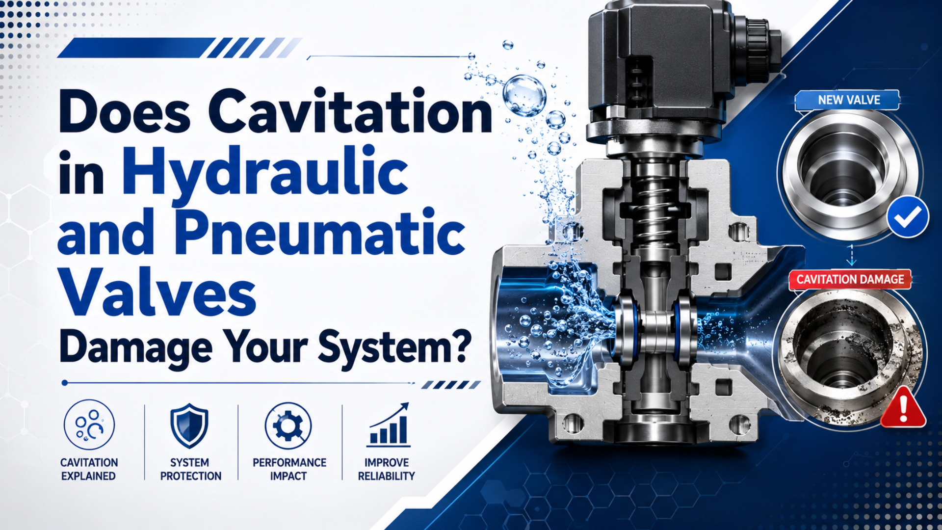
Cavitation can erode a liquid-service valve, but dry compressed air cannot cavitate in the same thermodynamic sense. In a hydraulic valve, liquid may vaporize at a low-pressure restriction and the vapor bubbles may collapse after pressure recovers. A pneumatic valve instead experiences compressible-gas effects such as choked flow, aerodynamic noise, cooling, condensation, or icing.
Emerson states the boundary directly: control-valve cavitation occurs only in liquid flow, and gases cannot cavitate. ISO 6358 uses a different model for pneumatic components, separating subsonic from choked compressible flow rather than treating gas expansion as liquid cavitation (Emerson, accessed 2026; ISO 6358-3, 2014).
Key Takeaways
- Liquid cavitation requires vapor formation, pressure recovery, and bubble collapse near a surface.
- Flashing remains a liquid-vapor mixture downstream.
- Dry compressed air may choke, cool, or create aerodynamic noise, but the gas does not cavitate.
- Before changing a valve, identify the fluid phase and record absolute pressure, temperature, moisture condition, valve response, and damage location.
This distinction matters because the remedies are different. Anti-cavitation trim can stage a liquid pressure drop. It cannot dry wet compressed air, enlarge an undersized pneumatic exhaust, or remove particles from a valve. For the gas-flow side of the problem, compare this guide with the pneumatic choked-flow explanation and the sonic-conductance guide.
What Actually Counts as Cavitation in a Valve?
Emerson tracks 3 liquid-pressure locations through a control valve: inlet pressure , minimum pressure at the vena contracta , and outlet pressure . Cavitation becomes possible when falls below liquid vapor pressure and later recovers above it (Control Valve Handbook, 2026).
Cavitation is the formation and subsequent collapse of vapor cavities in a liquid. The vena contracta is the narrowest part of the moving flow stream, normally just downstream of the physical restriction. Velocity is highest there, so static pressure reaches its minimum. If that minimum crosses the liquid’s vapor-pressure boundary, some liquid changes phase and forms vapor cavities.
The basic cavitation condition can be written as:
Here, is absolute pressure at the vena contracta, is the liquid’s absolute vapor pressure at operating temperature, and is absolute outlet pressure. Gauge pressure cannot be compared directly with absolute vapor pressure. Use one pressure reference throughout the calculation.
Pressure recovery is essential. The bubbles do not cause classic cavitation erosion merely because they form. Damage occurs when downstream pressure rises above , causing the vapor cavities to collapse. Repeated collapse near metal surfaces can produce localized loading, noise, vibration, and a rough pitted surface.
Pressure recovery closes the loop.
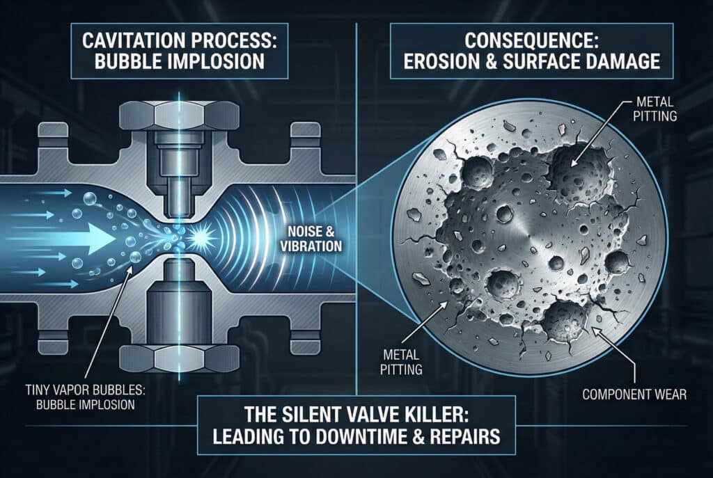
This diagram represents liquid service. Its vapor-bubble mechanism should not be applied to a valve carrying dry compressed air.
In our experience reviewing applications, the fluid phase is the fastest useful diagnostic gate. Ask whether liquid reaches the restriction before discussing cavitation. A valve in a hydraulic-oil circuit, water line, condensate service, or liquid process can cavitate. A pneumatic directional valve carrying dry gas needs a compressible-flow diagnosis instead. Entrained liquid water may create a separate liquid-phase problem, but the air itself is not the cavitating fluid.
Liquid Cavitation and Flashing Are Different Failure Modes
Emerson distinguishes 2 downstream outcomes after liquid pressure falls below : cavitation occurs when recovers above vapor pressure, while flashing persists when remains below it. Both may limit flow, but their erosion locations and suitable valve geometries differ (Emerson flashing guidance, accessed 2026).
Flashing is continued liquid-to-vapor conversion when pressure does not recover above the liquid’s vapor pressure. Its pressure relationship is:
The vapor does not collapse inside the valve because the outlet remains at or below vapor pressure. Emerson describes flashing erosion as generally smooth and shiny, driven by a high-velocity liquid-vapor mixture. Cavitation more often leaves irregular, crater-like pitting where bubbles collapse after pressure recovery. Why does the label matter during valve selection? A multistage trim may keep each liquid pressure drop above the cavitation boundary. Flashing cannot be stopped by trim if the system outlet pressure remains below vapor pressure; the design instead manages velocity, direction, material, and the downstream expansion area.
That is the practical divide.
| Condition | Pressure path | Phase behavior | Typical concern |
|---|---|---|---|
| No vaporization | Liquid remains liquid | Turbulence, velocity, ordinary wear | |
| Cavitation | Vapor forms, then collapses | Pitting, noise, vibration, trim damage | |
| Flashing | and | Vapor remains downstream | Smooth directional erosion, reduced density |
| Gas choked flow | Compressible gas reaches its critical pressure ratio | No liquid-vapor phase change required | Flow limit, aerodynamic noise, cooling |
IEC 60534-2-1 provides sizing equations for both compressible and incompressible flow and includes multistage sizing in an annex. It also limits the incompressible equations to suitable Newtonian liquids, which is another reason not to transfer one fluid model blindly between hydraulic and pneumatic applications (IEC 60534-2-1, 2011).
Why Doesn’t Dry Compressed Air Cavitate?
ISO 6358-3 describes 2 regimes for pneumatic component and piping calculations: subsonic flow and choked flow. Both concern compressible gas behavior. Emerson separately states that gases cannot cavitate, so a hissing pneumatic valve at critical flow is not evidence of vapor bubbles collapsing in a liquid (ISO 6358-3, 2014).
Choked flow is the gas-flow condition in which reducing downstream pressure no longer increases mass flow for the existing upstream state and restriction. The critical pressure ratio is model-specific and is commonly represented by in ISO 6358 component data:
No bubbles are required.
In this relationship, and are absolute upstream and downstream pressures, and is the component’s critical pressure ratio. Do not substitute a universal value for . Use the tested flow characteristics of the exact valve, fitting, tube, or manifold.
Choked gas flow can still cause trouble. The valve may produce intense aerodynamic noise, vibration, a lower local static temperature, and a flow ceiling that prevents the actuator from reaching its expected speed. Those are real engineering problems, but the causal model is different from liquid vaporization and collapse. For cylinder-speed complaints, start with available mass flow and the valve’s sonic conductance. The cylinder choked-flow guide covers the actuator consequence, while the valve pressure-drop guide explains how upstream and downstream pressure affect selection.
Pneumatic Failures Commonly Mistaken for Cavitation
Parker’s compressed-air example compresses 8 m3 of ambient air into 1 m3 at 7 bar gauge, then shows condensation as the air cools. SMC separately warns that humid compressed air can freeze when expansion lowers internal temperature. These are moisture and thermal problems, not gas cavitation (Parker, 2021; SMC, 2026).
Several pneumatic faults can create similar audible or performance symptoms:
- Choked flow: mass flow reaches a ceiling while the restriction produces strong aerodynamic noise.
- Adiabatic cooling: rapid expansion lowers local gas temperature, particularly during a sustained high-flow exhaust or continuous air-powered process.
- Condensation and icing: moisture reaches a cold pilot passage and can obstruct a small orifice, exhaust path, spool end, or silencer.
- Particle erosion: debris scratches seats.
- Lubricant or seal problems: incompatible oil, washed-out grease, swelling, or hardened seals create friction and leakage without any fluid phase change.
- Exhaust back pressure: a blocked silencer or shared manifold delays transfer. The pressure pulse may also disturb another valve station.
Water changes the diagnosis.
The adiabatic-expansion guide explains the temperature mechanism. If liquid water is present, use the pneumatic water-damage guide to trace the dryer, drains, low points, and point-of-use treatment. Do not diagnose by sound alone. A high-pitched hiss often indicates gas velocity. Intermittent sticking after long exhaust events can indicate icing. Brown residue suggests corrosion or dirty condensate. A valve that shifts late only when another station exhausts may have a common-exhaust back-pressure problem rather than damage at its flow restriction.
What Damage Patterns Separate Cavitation from Other Wear?
Fisher’s severe-service micro-trim bulletin separates 2 cavitation strategies: isolation trim controls where cavitation occurs to limit trim damage, while elimination trim changes the pressure path to eliminate its effects. That distinction shows why damage location matters more than a generic report of valve noise (Fisher Micro Trims, 2019).
Inspect the component only after isolating and depressurizing it under the applicable procedure. Record where the surface change begins, the direction it follows, and whether loose particles are present. Compare the pattern with the actual fluid and pressure path.
Damage geometry is evidence.
| Observation | More consistent with | What to verify next |
|---|---|---|
| Rough, irregular pitting near pressure recovery | Liquid cavitation | Absolute inlet/outlet pressure, fluid vapor pressure, valve recovery factor |
| Smooth, directional downstream erosion | Flashing or liquid-droplet impingement | Outlet pressure versus vapor pressure, velocity, geometry, material |
| Seat scratches aligned with flow and loose debris | Particle contamination | Filter rating, oil cleanliness, pipe scale, desiccant carryover |
| Frost, ice, or intermittent cold sticking | Moist compressed air and expansion cooling | Pressure dew point, ambient temperature, duty cycle, exhaust temperature |
| Whistling without pitting | High gas velocity or choked flow | Sonic conductance, critical pressure ratio, downstream pressure, silencer |
| Chatter linked to another manifold station | Exhaust interaction or pilot instability | Ports 3/5, pilot exhaust, supply pressure, simultaneous commands |
Noise and vibration remain useful triggers for investigation, but neither proves cavitation. Emerson notes that control-valve vibration can also arise from aerodynamic noise and high pressure-drop effects. Link the acoustic event to pressure, flow, temperature, and valve position before assigning a mechanism (Emerson control-valve vibration, accessed 2026). Metal debris in hydraulic oil is likewise evidence of wear, not proof of its cause. Confirm the alloy and likely source when possible. Pump damage, bearing wear, cylinder scoring, and contaminated maintenance work can all contribute particles that later mark a valve seat.
A Diagnostic Procedure for Suspected Valve Damage
ISO 4413 and ISO 4414 are both 3rd-edition, 2010 safety standards for hydraulic and pneumatic systems. They cover design, installation, adjustment, maintenance, and reliable operation. Use the correct system standard before opening a line, removing a silencer, or inspecting a valve with trapped energy (ISO 4413; ISO 4414).
Start with the medium and the exact valve code. A process control valve, mobile hydraulic directional valve, and pneumatic solenoid valve can all be called a control valve, but their pressure ratings, test data, failure mechanisms, and safe isolation procedures are not interchangeable.
Record the fault on a common time base:
- Identify the working fluid. Record the exact liquid or gas, any mixed phase, contamination state, temperature, and the manufacturer data needed to establish vapor pressure or pneumatic flow characteristics.
- Measure pressure at the valve. Use upstream and downstream absolute pressure where vapor pressure or critical pressure ratio is involved.
- Record command and travel. Log coil current, pilot pressure, stem or spool feedback, and working-port response where available.
- Measure temperature. Include liquid temperature or pressure dew point as appropriate.
- Compare operating states. Test individual and simultaneous operation, low supply, maximum flow, cold start, thermal equilibrium, and the exact cycle that produces the complaint.
- Inspect the flow path. Check strainers and filters first. Then inspect silencers, exhaust tubing, pressure zones, drains, coolers, reservoir level, and every recent piping change before condemning the valve.
- Examine damage safely. Photograph pitting, erosion, deposits, ice evidence, scoring, and debris in their original orientation.
One trace is not enough.
The most useful evidence is a boundary crossing. For a liquid valve, show that estimated vena-contracta pressure crosses vapor pressure and that outlet pressure recovers. For a pneumatic valve, show that the pressure ratio reaches the component’s critical value or that temperature falls below the moisture limit. Noise without a boundary measurement remains ambiguous. If the problem is pneumatic pressure loss rather than fluid phase change, follow the pressure-drop troubleshooting guide. For a pilot-operated directional valve that misses shifts, use the pilot back-pressure guide to separate main exhaust, pilot exhaust, and supply-pressure effects.
How Can Hydraulic Cavitation Damage Be Reduced?
Fisher’s CAV4 valve is a product-specific example for pressure drops above 207 bar, and its staged trim takes more than 90% of the total drop in early stages where cavity formation risk is lower. The figures are not universal limits; they demonstrate the principle of distributing pressure reduction (Fisher CAV4, accessed 2026).
Choose the remedy from the system pressure profile, not from valve style alone:
- Restore inlet pressure when the supply or suction boundary is too low.
- Reduce the pressure drop assigned to one restriction by staging it across elements that are sized for the actual liquid, flow range, temperature, and installed piping.
- Select recovery characteristics and anti-cavitation trim from verified manufacturer data.
- Lower liquid temperature only when the process permits and the full system consequence is understood, because vapor pressure changes with temperature.
- Correct reservoir starvation, blocked suction paths, low oil level, and unintended negative work-port pressure.
- Use make-up or anti-cavitation checks where the circuit analysis requires them, not as a generic accessory.
- For flashing, choose downstream geometry and material that manage sustained liquid-vapor velocity.
The pressure profile chooses the remedy.
Bosch Rexroth describes one anti-cavitation cartridge as providing make-up flow when leakage or an overrunning load leaves insufficient oil volume. Parker similarly offers work-port anti-cavitation valves that admit oil from the tank gallery during under-pressure. These devices address a particular hydraulic boundary and must be selected from the exact circuit data (Bosch Rexroth, 2023; Parker P70, accessed 2026). Do not promise that hardened material alone will solve the problem. Hard trim may resist erosion longer, but repeated vapor collapse or high-velocity flashing still consumes material. Correct the pressure path first, then use suitable geometry and material to manage the remaining exposure.
How Should Pneumatic Valve Problems Be Corrected?
ISO 6358-1 defines steady-state testing for pneumatic components with fixed or variable internal flow paths, while its 2026 Amendment 2 adds measurement-uncertainty treatment. Use tested conductance and critical-ratio data for the exact component instead of applying a liquid cavitation rule to compressed air (ISO 6358-1, 2013; Amendment 2, 2026).
If flow is inadequate, compare the required actuator flow with the complete valve, manifold, fitting, tubing, and exhaust path. An oversized valve body cannot compensate for a small manifold passage or long restricted exhaust tube. The pneumatic valve-sizing guide provides the next step when the complaint is slow motion rather than icing or contamination.
If moisture or freezing is present:
- measure pressure dew point at the valve, not just compressor-room relative humidity;
- verify the aftercooler and separator first, then the dryer, receiver, automatic drains, filters, low points, and point-of-use treatment;
- compare cold ambient conditions and continuous expansion duty with the selected dryer’s actual outlet specification;
- protect exhaust and pilot vents without creating excessive back pressure or trapping condensate;
- remove standing water safely;
- after correcting air quality, inspect seals, lubricant condition, spool surfaces, pilot orifices, and downstream components for damage that will not disappear by itself.
Correct the measured boundary.
If noise is the main symptom, determine whether it comes from the supply restriction, valve trim, actuator exhaust, silencer, or piping. A silencer can reduce exhaust noise, but a clogged or undersized unit raises back pressure. The silencer-clogging guide explains that separate failure path. Changing pressure without naming the mechanism can make the diagnosis worse. Raising pneumatic supply may increase actuator speed while also increasing exhaust mass flow and cooling. Adding hydraulic back pressure may suppress cavitation in one liquid application yet increase energy loss or load elsewhere. Change one verified boundary, then repeat the same loaded test.
Valve Cavitation FAQs: What Should Engineers Ask?
Two standards define the split: IEC 60534-2-1 covers installed control-valve sizing for compressible and incompressible fluids, while ISO 6358 covers pneumatic components using compressible fluids. These 5 answers keep liquid phase change, gas-flow limits, moisture, and valve damage in the correct engineering model (IEC; ISO).
Can cavitation occur in a pneumatic valve carrying dry air?
No. Emerson states that valve cavitation occurs only in liquid flow and gases cannot cavitate. Dry compressed air can reach choked flow, generate aerodynamic noise, cool during expansion, or produce vibration. If liquid water is entrained, diagnose that liquid separately rather than calling every pneumatic restriction pseudo-cavitation (Emerson, accessed 2026).
What is the practical difference between cavitation and flashing?
Cavitation requires outlet pressure to recover above the liquid’s vapor pressure, so vapor bubbles collapse. During flashing, outlet pressure remains at or below vapor pressure and the liquid-vapor mixture continues downstream. Emerson recommends different geometry and material strategies because flashing erosion cannot be prevented by the valve alone (Emerson, accessed 2026).
Does a noisy valve prove that cavitation is occurring?
No. Cavitation can create noise and vibration in liquid service, but pneumatic restrictions also generate aerodynamic noise and may choke without any liquid phase change. Record fluid state, absolute inlet and outlet pressure, temperature, valve position, and damage pattern before selecting a remedy (Emerson, accessed 2026).
Can moisture freeze inside a pneumatic valve?
Yes. SMC warns that compressed-air expansion lowers internal temperature and that humid air can freeze when ambient temperature is low. Confirm pressure dew point, dryer performance, drainage, expansion duty, and local temperature. Freezing is a moisture and thermal-control problem, not cavitation of the air itself (SMC, 2026).
Should engineers use a universal pressure-drop limit?
No. Liquid cavitation depends on fluid vapor pressure, temperature, valve recovery, inlet pressure, and outlet pressure. Pneumatic choked flow depends on absolute pressure ratio and component-specific flow data. Use IEC 60534 or ISO 6358 methods plus the exact manufacturer limits rather than one percentage for every valve (IEC; ISO).
Sources and technical references
- Emerson, Control Valve Handbook, 2026. Retrieved 2026-07-22.
- Emerson, Cavitation in Control Valves. Retrieved 2026-07-22.
- Emerson, Control Valve Flashing. Retrieved 2026-07-22.
- IEC 60534-2-1, Industrial-Process Control Valve Sizing Equations, 2011. Retrieved 2026-07-22.
- ISO 6358-1, Pneumatic Component Steady-State Flow Testing, 2013. Retrieved 2026-07-22.
- ISO 6358-3, Pneumatic System Flow-Rate Calculations, 2014. Retrieved 2026-07-22.
- ISO 6358-1:2013/Amd 2, Measurement Uncertainty, 2026. Retrieved 2026-07-22.
- SMC, 56-PA Installation and Maintenance Manual, 2026. Retrieved 2026-07-22.
- Parker, Compressed Air Contamination, 2021. Retrieved 2026-07-22.
- ISO 4413, Hydraulic Fluid Power Safety Requirements, 2010. Retrieved 2026-07-22.
- ISO 4414, Pneumatic Fluid Power Safety Requirements, 2010. Retrieved 2026-07-22.
- Fisher, Severe Service Micro Trims, 2019. Retrieved 2026-07-22.
- Bosch Rexroth, Anti-Cavitation Valve with Pressure Cut-Off Stage, 2023. Retrieved 2026-07-22.