

Are you struggling to predict your pneumatic cylinder’s actual performance? Many engineers miscalculate force outputs and pressure requirements, leading to system failures and costly downtime. But there’s a simple way to master these calculations.
Pneumatic cylinders operate according to fundamental physics principles, primarily Pascal’s Law1, which states that pressure applied to a confined fluid is transmitted equally in all directions. This allows us to calculate cylinder force by multiplying pressure by the effective piston area, with flow rates and pressure units requiring precise conversions for accurate system design.
I’ve spent over a decade helping customers optimize their pneumatic systems, and I’ve seen how understanding these basic principles can transform system reliability. Let me share the practical knowledge that will help you avoid the common mistakes I see every day.
Table of Contents
- How Does Pascal’s Law Determine Cylinder Force Output?
- What’s the Relationship Between Air Flow and Pressure in Cylinders?
- Why Is Understanding Pressure Unit Conversion Critical for System Design?
- Conclusion
- FAQs About Physics in Pneumatic Systems
How Does Pascal’s Law Determine Cylinder Force Output?
Understanding Pascal’s Law is fundamental to predicting and optimizing cylinder performance in any pneumatic system.
Pascal’s Law states that pressure exerted on a fluid in a closed system is transmitted equally throughout the fluid. For pneumatic cylinders, this means the force output equals the pressure multiplied by the effective piston area (F = P × A). This simple relationship is the foundation for all cylinder force calculations.

The Force Calculation Derivation
Let’s break down the mathematical derivation of cylinder force calculations:
Basic Force Equation
The fundamental equation for cylinder force is:
F = P × A
Where:
- F = Force output (N)
- P = Pressure (Pa)
- A = Effective piston area (m²)
Effective Area Considerations
The effective area differs depending on cylinder type and direction:
| Cylinder Type | Extension Force | Retraction Force |
|---|---|---|
| Single-acting | P × A | Spring force only |
| Double-acting (standard) | P × A | P × (A – a) |
| Double-acting (rodless) | P × A | P × A |
Where:
- A = Full piston area
- a = Rod cross-sectional area
I once consulted with a manufacturing plant in Ohio that was experiencing insufficient force in their pressing application. Their calculations seemed correct on paper, but the actual performance was lacking. Upon investigation, I discovered they were using gauge pressure2 in their calculations instead of absolute pressure, and they hadn’t accounted for the rod area during retraction. After recalculating with the correct formula and pressure values, we were able to properly size their system, increasing productivity by 23%.
Practical Force Calculation Examples
Let’s examine some real-world calculations:
Example 1: Extension Force in a Standard Cylinder
For a cylinder with:
- Bore diameter = 50mm (radius = 25mm = 0.025m)
- Operating pressure = 6 bar (600,000 Pa)
The piston area is:
A = π × r² = π × (0.025)² = 0.001963 m²
The extension force is:
F = P × A = 600,000 Pa × 0.001963 m² = 1,178 N ≈ 118 kg force
Example 2: Retraction Force in the Same Cylinder
If the rod diameter is 20mm (radius = 10mm = 0.01m):
The rod area is:
a = π × r² = π × (0.01)² = 0.000314 m²
The effective retraction area is:
A – a = 0.001963 – 0.000314 = 0.001649 m²
The retraction force is:
F = P × (A – a) = 600,000 Pa × 0.001649 m² = 989 N ≈ 99 kg force
Efficiency Factors in Real-World Applications
In practical applications, several factors affect the theoretical force calculation:
Friction Losses
Friction between the piston seal and cylinder wall reduces effective force:
| Seal Type | Typical Efficiency Factor |
|---|---|
| Standard NBR | 0.85-0.90 |
| Low-friction PTFE | 0.90-0.95 |
| Aged/worn seals | 0.70-0.85 |
Practical Force Equation
A more accurate real-world force equation is:
F_actual = η × P × A
Where:
- η (eta) = Efficiency factor (typically 0.85-0.95)
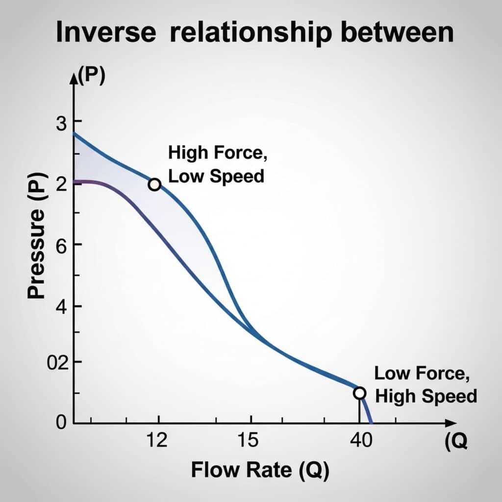
What’s the Relationship Between Air Flow and Pressure in Cylinders?
Understanding the relationship between flow rate and pressure is crucial for sizing air supply systems and predicting cylinder speed.
Air flow and pressure in pneumatic systems are inversely related—as pressure increases, flow typically decreases. This relationship follows gas laws and is affected by restrictions, temperature, and system volume. Proper cylinder operation requires balancing these factors to achieve desired speed and force.
Flow-Pressure Conversion Table
This practical reference table shows the relationship between flow rate and pressure drop across various system components:
| Pipe Size (mm) | Flow Rate (l/min) | Pressure Drop (bar/meter) at 6 bar Supply |
|---|---|---|
| 4 | 100 | 0.15 |
| 4 | 200 | 0.45 |
| 4 | 300 | 0.90 |
| 6 | 200 | 0.08 |
| 6 | 400 | 0.25 |
| 6 | 600 | 0.50 |
| 8 | 400 | 0.06 |
| 8 | 800 | 0.18 |
| 8 | 1200 | 0.35 |
| 10 | 600 | 0.04 |
| 10 | 1200 | 0.12 |
| 10 | 1800 | 0.24 |
The Mathematics of Flow and Pressure
The relationship between flow and pressure follows several gas laws:
Poiseuille’s Equation3 for Laminar Flow
For laminar flow through pipes:
Q = (π × r⁴ × ΔP) / (8 × η × L)
Where:
- Q = Volumetric flow rate
- r = Pipe radius
- ΔP = Pressure difference
- η = Dynamic viscosity
- L = Pipe length
Flow Coefficient (Cv)4 Method
For components like valves:
Q = Cv × √ΔP
Where:
- Q = Flow rate
- Cv = Flow coefficient
- ΔP = Pressure drop across the component
Cylinder Speed Calculation
The speed of a pneumatic cylinder depends on the flow rate and the cylinder area:
v = Q / A
Where:
- v = Cylinder speed (m/s)
- Q = Flow rate (m³/s)
- A = Piston area (m²)
During a recent project at a packaging facility in France, I encountered a situation where the client’s rodless cylinders were moving too slowly despite adequate pressure. By analyzing their system using our flow-pressure calculations, we identified undersized supply lines causing significant pressure drop. After upgrading from 6mm to 10mm tubing, their cycle time improved by 40%, dramatically increasing production capacity.
Critical Flow Considerations
Several factors affect the flow-pressure relationship in pneumatic systems:
Choked Flow Phenomenon5
When the pressure ratio exceeds a critical value (approximately 0.53 for air), flow becomes “choked” and cannot increase regardless of downstream pressure reduction.
Temperature Effects
Flow rate is affected by temperature according to the relationship:
Q₂ = Q₁ × √(T₂/T₁)
Where:
- Q₁, Q₂ = Flow rates at different temperatures
- T₁, T₂ = Absolute temperatures
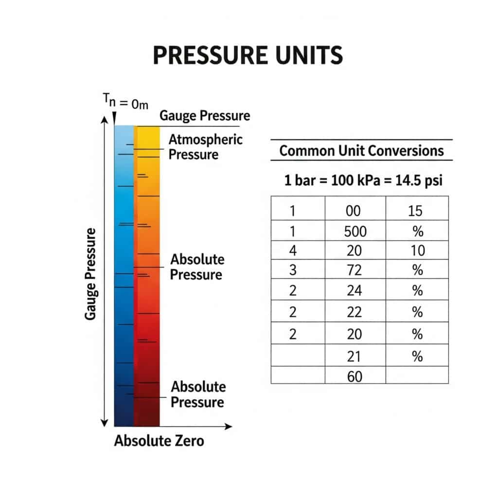
Why Is Understanding Pressure Unit Conversion Critical for System Design?
Navigating the various pressure units used worldwide is essential for proper system design and international compatibility.
Pressure unit conversion is critical because pneumatic components and specifications use different units depending on region and industry. Misinterpreting units can lead to significant calculation errors, with potentially dangerous consequences. Converting between absolute, gauge, and differential pressure adds another layer of complexity.
Absolute Pressure Unit Conversion Guide
This comprehensive conversion table helps navigate the various pressure units used globally:
| Unit | Symbol | Equivalent in Pa | Equivalent in bar | Equivalent in psi |
|---|---|---|---|---|
| Pascal | Pa | 1 | 1 × 10⁻⁵ | 1.45 × 10⁻⁴ |
| Bar | bar | 1 × 10⁵ | 1 | 14.5038 |
| Pound per square inch | psi | 6,894.76 | 0.0689476 | 1 |
| Kilogram-force per square cm | kgf/cm² | 98,066.5 | 0.980665 | 14.2233 |
| Megapascal | MPa | 1 × 10⁶ | 10 | 145.038 |
| Atmosphere | atm | 101,325 | 1.01325 | 14.6959 |
| Torr | Torr | 133.322 | 0.00133322 | 0.0193368 |
| Millimeter of mercury | mmHg | 133.322 | 0.00133322 | 0.0193368 |
| Inch of water | inH₂O | 249.089 | 0.00249089 | 0.0361274 |
Absolute vs. Gauge Pressure
Understanding the difference between absolute and gauge pressure is fundamental:
Pressure Conversion Calculator
Pressure Unit Converter
Cylinder Flow Rate Converter
Conversion Formulas
- P_absolute = P_gauge + P_atmospheric
- P_gauge = P_absolute – P_atmospheric
Where standard atmospheric pressure is approximately:
- 1.01325 bar
- 14.7 psi
- 101,325 Pa
I once worked with an engineering team in Germany who had purchased our rodless cylinders but reported they weren’t achieving the expected force. After some troubleshooting, we discovered they were using our force charts (which were based on gauge pressure) but inputting absolute pressure values. This simple misunderstanding was causing a 1 bar miscalculation in their force expectations. After clarifying the pressure reference, their system performed exactly as specified.
Practical Conversion Examples
Let’s work through some common conversion scenarios:
Example 1: Converting Working Pressure Across Units
A cylinder rated for 0.7 MPa maximum working pressure:
In bar:
0.7 MPa × 10 bar/MPa = 7 bar
In psi:
0.7 MPa × 145.038 psi/MPa = 101.5 psi
Example 2: Converting from Gauge to Absolute Pressure
A system operating at 6 bar gauge pressure:
In absolute pressure (bar):
6 bar_gauge + 1.01325 bar_atmospheric = 7.01325 bar_absolute
Example 3: Converting from kgf/cm² to MPa
A Japanese cylinder specified for 7 kgf/cm²:
In MPa:
7 kgf/cm² × 0.0980665 MPa/(kgf/cm²) = 0.686 MPa
Regional Pressure Unit Preferences
Different regions typically use different pressure units:
| Region | Common Pressure Units |
|---|---|
| North America | psi, inHg, inH₂O |
| Europe | bar, Pa, mbar |
| Japan | kgf/cm², MPa |
| China | MPa, bar |
| UK | bar, psi, Pa |
Pressure Measurement in Documentation
When documenting pressure specifications, it’s essential to clearly indicate:
- The numerical value
- The unit of measurement
- Whether it’s gauge (g) or absolute (a) pressure
For example:
- 6 bar_g (gauge pressure, 6 bar above atmospheric)
- 7.01 bar_a (absolute pressure, total pressure including atmospheric)
Conclusion
Understanding the physics behind pneumatic cylinders—from Pascal’s Law force calculations to flow-pressure relationships and pressure unit conversions—is essential for proper system design and troubleshooting. These fundamental principles help ensure your pneumatic systems deliver the expected performance reliably and efficiently.
FAQs About Physics in Pneumatic Systems
How do I calculate the force output of a rodless pneumatic cylinder?
To calculate the force output of a rodless pneumatic cylinder, multiply the operating pressure by the effective piston area (F = P × A). For example, a rodless cylinder with a 50mm bore (0.001963 m² area) operating at 6 bar (600,000 Pa) will produce approximately 1,178 N of force. Unlike traditional cylinders, rodless cylinders typically have the same effective area in both directions.
What’s the difference between gauge pressure and absolute pressure?
Gauge pressure (bar_g, psi_g) measures pressure relative to atmospheric pressure, with atmospheric pressure being zero. Absolute pressure (bar_a, psi_a) measures pressure relative to a perfect vacuum, which is zero. To convert from gauge to absolute pressure, add atmospheric pressure (approximately 1.01325 bar or 14.7 psi) to the gauge reading.
How does air flow affect cylinder speed?
Cylinder speed is directly proportional to the air flow rate and inversely proportional to the piston area (v = Q/A). Insufficient flow rate due to undersized supply lines, restrictive fittings, or inadequate valves will limit cylinder speed regardless of pressure. For example, a flow rate of 20 liters/second through a cylinder with a 0.002 m² piston area will produce a speed of 10 meters/second.
Why do pneumatic cylinders sometimes move slower than calculated?
Pneumatic cylinders may move slower than calculated due to several factors: air supply restrictions causing pressure drops, internal friction from seals, mechanical loads exceeding calculations, leakage reducing effective pressure, or temperature effects on air density. Additionally, valve flow coefficients often limit the actual flow rate available to the cylinder.
How do I convert between different pressure units for international specifications?
To convert between pressure units, use multiplication factors: 1 bar = 100,000 Pa = 0.1 MPa = 14.5038 psi = 1.01972 kgf/cm². Always verify whether the pressure is specified as gauge or absolute, as this distinction can significantly affect calculations. For example, 6 bar_g equals 7.01325 bar_a at standard atmospheric conditions.
What is the relationship between cylinder bore size and force output?
The relationship between cylinder bore size and force output is quadratic—doubling the bore diameter increases the force output by four times (since area = π × r²). For example, at 6 bar operating pressure, a 40mm bore cylinder produces approximately 754 N of force, while an 80mm bore cylinder produces about 3,016 N, nearly four times greater.
-
Provides a detailed explanation of Pascal’s Law, a fundamental principle in fluid mechanics that is the basis for hydraulic and pneumatic power transmission. ↩
-
Offers a clear definition and comparison of gauge and absolute pressure, a critical distinction for accurate engineering calculations as gauge pressure is relative to atmospheric pressure. ↩
-
Explains the derivation and application of Poiseuille’s law, which describes the pressure drop of an incompressible and Newtonian fluid flowing through a long cylindrical pipe in the laminar regime. ↩
-
Provides a technical definition of the Flow Coefficient (Cv), an imperial measurement that provides a standardized way to compare the flow capacities of different valves. ↩
-
Details the physics of choked flow, a fluid dynamics condition that limits the mass flow rate of a compressible fluid through a restriction when the velocity reaches the speed of sound. ↩
