
Your machine tool is producing dimensional variation across a production shift because the pneumatic clamping pressure at the fixture drops 0.4 bar when the adjacent press cycle fires and draws down the shared supply manifold. Your paint robot is generating gloss variation because the atomizing air pressure at the spray gun fluctuates with every valve actuation on the same distribution line. Your assembly torque tool is delivering inconsistent fastener torque because the supply pressure at the tool inlet varies by 0.8 bar between peak demand and idle periods on your centralized FRL system. You specified your compressed air treatment and regulation by the textbook method — one centralized FRL unit at the machine inlet, sized for total flow, set to the highest pressure any device on the machine requires — and every device that requires a pressure different from that setting, or that requires pressure stability independent of other devices on the same supply, is operating outside its specified condition on every cycle. 🔧
Centralized FRL systems are the correct specification for machines and systems where all downstream devices operate at the same pressure, where total flow can be served by a single filter-regulator-lubricator sized for the aggregate demand, and where the installation and maintenance simplicity of a single treatment point outweighs the pressure independence that point-of-use regulation provides. Point-of-use regulators are the correct specification for any machine or system where individual devices require different operating pressures, where pressure stability at a specific device must be maintained independent of demand fluctuations elsewhere on the same supply, where a device requires a pressure lower than the machine supply, or where the pressure at a critical device must be held within a tolerance tighter than the centralized regulator can maintain across the full range of system demand conditions.
Take Mei-Ling, a process engineer at a precision electronics assembly plant in Shenzhen, China. Her SMT pick-and-place machine had a centralized FRL set to 5 bar — the pressure required by the main gantry drive cylinders. Her vacuum generator, which required 3.5 bar for optimal vacuum level and air consumption, was operating at 5 bar — consuming 40% more compressed air than necessary and generating a vacuum level 15% higher than the component handling specification required, causing component damage on fine-pitch BGAs. Her pneumatic screwdrivers required 4 bar for torque calibration — at 5 bar they were over-torquing fasteners by 18%. Adding point-of-use regulators at the vacuum generator (set to 3.5 bar) and at each screwdriver station (set to 4 bar) — while retaining the centralized FRL for the gantry drives — reduced compressed air consumption by 22%, eliminated component handling damage, and brought fastener torque within specification on every station. 🔧
Table of Contents
- What Are the Core Functional Differences Between Centralized FRL and Point-of-Use Regulation?
- When Is a Centralized FRL System the Correct Specification?
- Which Applications Require Point-of-Use Regulators for Reliable Performance?
- How Do Centralized FRL and Point-of-Use Regulators Compare in Pressure Stability, Air Quality, and Total Cost?
What Are the Core Functional Differences Between Centralized FRL and Point-of-Use Regulation?
The functional difference between these two approaches is not a matter of component quality — it is a matter of where pressure is set and maintained relative to the device that requires it, and how many devices share a single pressure setting. 🤔
A centralized FRL system sets one supply pressure for all downstream devices from a single regulator located at the machine or system inlet — every device downstream of that regulator receives the same regulated pressure, modified only by the pressure drop in the distribution tubing between the regulator and the device. A point-of-use regulator is installed immediately upstream of a specific device and sets the pressure for that device independently of the supply pressure and independently of pressure fluctuations caused by other devices on the same supply — each point-of-use regulator maintains its set pressure at its outlet regardless of what the supply pressure is doing, as long as the supply pressure remains above the regulator’s set point plus its minimum differential pressure requirement.

Core Architecture Comparison
| Property | Centralized FRL | Point-of-Use Regulator |
|---|---|---|
| Regulation location | Machine / system inlet | Immediately upstream of device |
| Pressure setting | One setting for all downstream devices | Individual setting per device |
| Devices at different pressures | ❌ Not possible from single unit | ✅ Each device independently set |
| Pressure stability at device | Affected by distribution drop + demand | ✅ Maintained at device inlet |
| Supply pressure fluctuation effect | Propagates to all devices | ✅ Rejected — regulator absorbs |
| Demand fluctuation isolation | ❌ All devices share supply drop | ✅ Each device isolated |
| Filter element location | Centralized — one element | Supplementary — per device if required |
| Lubricator location | Centralized — one lubricator | Supplementary — per device if required |
| Installation complexity | ✅ Simple — one unit | Multiple units — one per device |
| Maintenance points | ✅ Single — one FRL | Multiple — one per regulator |
| Compressed air consumption optimization | ❌ All devices at highest required pressure | ✅ Each device at minimum required pressure |
| Pressure drop in distribution | Affects all devices | ✅ Compensated at point of use |
| Critical device pressure tolerance | Limited by distribution variability | ✅ Tight — regulator at device |
| ISO 8573 compliance point | At FRL outlet | At FRL outlet (filter) + device inlet (pressure) |
| Unit cost | ✅ Lower — one FRL | Higher — multiple regulators |
| Total system cost | ✅ Lower (simple systems) | Higher (complex systems) — offset by performance |
The Pressure Drop Problem — Why Centralized Regulation Fails at the Device
The pressure at any device downstream of a centralized FRL is:
Where:
- = static pressure drop in tubing at device flow rate
- = dynamic pressure drop from simultaneous demand on shared supply
Distribution pressure drop (Hagen-Poiseuille for laminar, darcy-weisbach1 for turbulent):
For a 6mm ID tube, 3m length, 100 Nl/min flow:
Dynamic demand drop — when adjacent cylinder fires simultaneously:
For a DN25 cylinder drawing 500 Nl/min on a shared manifold:
Total pressure variation at device: 0.15 + 0.5 = 0.65 bar — the variation that was causing Mei-Ling’s torque tool non-conformance in Shenzhen and that a point-of-use regulator at the tool inlet eliminates by regulating to the set point regardless of upstream fluctuation.
⚠️ Critical Design Principle: A regulator can only reduce pressure — it cannot increase it. A point-of-use regulator requires the supply pressure at its inlet to be consistently above the device set point plus the regulator’s minimum differential pressure (typically 0.5–1.0 bar). If the centralized FRL supply drops below this threshold during peak demand, the point-of-use regulator loses regulation authority and the device pressure drops. The centralized FRL must be set high enough to maintain supply above all point-of-use regulator set points plus their differential requirements under worst-case simultaneous demand.
At Bepto, we supply centralized FRL units, point-of-use miniature regulators, regulator rebuild kits, filter element replacements, and lubricator wick and bowl assemblies for all major pneumatic brand FRL and regulator products — with flow capacity, pressure range, and port size confirmed on every product. 💰
When Is a Centralized FRL System the Correct Specification?
Centralized FRL systems are the correct and most common specification for the majority of industrial machine pneumatic supply applications — because the conditions that make centralized regulation inadequate are specific and identifiable, and when those conditions are absent, centralized FRL delivers the simpler, lower-maintenance architecture with fully adequate pressure control. ✅
Centralized FRL systems are the correct specification for machines and systems where all pneumatic devices operate at the same pressure or where pressure differences between devices are small enough to be accommodated by fixed orifice restrictors rather than regulators, where the total flow demand is consistent enough that distribution pressure drops are predictable and acceptable, where maintenance simplicity and single-point filter element replacement are operational priorities, and where the machine layout concentrates pneumatic devices close enough to the FRL that distribution pressure drops are within acceptable limits.
Ideal Applications for Centralized FRL Systems
- 🏭 Simple pneumatic machines — all cylinders at same pressure
- 🔧 Pneumatic tool stations — all tools at same rated pressure
- 📦 Packaging machinery — consistent pressure throughout cycle
- ⚙️ Conveyor pneumatics — actuators at uniform pressure
- 🚗 Fixture clamping — all clamps at same clamping pressure
- 🏗️ General automation — standard 5–6 bar throughout
- 🔩 Valve island supply — manifold-mounted valves at same pressure
Centralized FRL Selection by System Condition
| System Condition | Centralized FRL Correct? |
|---|---|
| All devices at same pressure | ✅ Yes — single setting serves all |
| Pressure differences < 0.5 bar between devices | ✅ Yes — fixed restrictors can compensate |
| Distribution tubing < 2m to furthest device | ✅ Yes — distribution drop negligible |
| Consistent demand — no large simultaneous actuations | ✅ Yes — no significant demand drop |
| Maintenance simplicity is priority | ✅ Yes — single element, single bowl |
| All devices tolerate ±0.3 bar pressure variation | ✅ Yes — centralized regulation adequate |
| Devices require different pressures (> 0.5 bar difference) | ❌ Point-of-use required |
| Critical device requires ±0.1 bar stability | ❌ Point-of-use required |
| Long distribution runs (> 5m to device) | ⚠️ Verify distribution drop |
| Large simultaneous demand events | ⚠️ Verify demand drop at critical devices |
Centralized FRL Sizing — The Correct Approach
Centralized FRL sizing requires three calculations that most selection guides reduce to a single flow coefficient lookup:
Step 1 — Total peak flow demand:
Where is the simultaneity-factor2 for device (fraction of devices actuating simultaneously).
Step 2 — FRL flow capacity at operating pressure:
Select FRL with ≥ calculated value at maximum acceptable pressure drop (typically 0.1–0.2 bar across FRL).
Step 3 — Filter element capacity:
Select bowl capacity ≥ condensate rate × drain interval (with 2× safety margin).
Centralized FRL — Correct Pressure Setting
The centralized FRL must be set to satisfy the highest-pressure device plus distribution losses:
| Component | Typical Value |
|---|---|
| Highest device pressure | Application-specific |
| Max distribution drop | 0.1–0.3 bar |
| Max demand drop | 0.2–0.6 bar |
| Safety margin | 0.3–0.5 bar |
| Total FRL set point | Device max + 0.6–1.4 bar |
Consequence of this calculation: If your highest-pressure device requires 5 bar and your distribution and demand drops total 1 bar, your FRL must be set to 6 bar — and every device that requires less than 5 bar is receiving 5 bar (minus its distribution drop), operating above its specified pressure, consuming more air than necessary, and potentially operating outside its performance specification. This is the condition that drove Mei-Ling’s component damage and torque non-conformance in Shenzhen — and the condition that point-of-use regulation resolves.
Lars, a machine design engineer at a hydraulic valve manufacturing plant in Gothenburg, Sweden, uses centralized FRL systems for all his assembly fixtures — every fixture uses the same 5.5 bar clamping pressure, his distribution runs are under 1.5m, his demand is sequential (never simultaneous), and his pressure variation at any fixture is under 0.15 bar. His centralized FRL delivers exactly what his application requires, with a single filter element to replace and a single bowl to drain. 💡
Which Applications Require Point-of-Use Regulators for Reliable Performance?
Point-of-use regulators address the pressure control problems that centralized regulation cannot solve — and in the applications where these problems occur, point-of-use regulation is not a preference but a functional requirement for process conformance. 🎯
Point-of-use regulators are required for any application where individual devices must operate at pressures different from the centralized supply, where pressure stability at a specific device must be maintained within tolerances tighter than the centralized system can provide, where a device’s performance is sensitive to pressure variation caused by other devices on the same supply, and where compressed air consumption optimization requires each device to operate at its minimum required pressure rather than the highest pressure any device on the system requires.
Applications Requiring Point-of-Use Regulators
| Application | Why Point-of-Use Regulation Required |
|---|---|
| Pneumatic torque tools | Torque calibration pressure-dependent — ±0.1 bar tolerance |
| Spray painting / atomization | Atomizing pressure determines droplet size and finish quality |
| Vacuum generators | Optimal vacuum at specific supply pressure — over-pressure wastes air |
| Precision pneumatic cylinders | Force output pressure-dependent — fixture clamping force critical |
| Pneumatic balancers | Balance pressure must match load — varies per workpiece |
| Pressure-sensitive test equipment | Test pressure must be exact — calibration requirement |
| Blow-off nozzles (air consumption) | Minimum pressure for task — over-pressure wastes air |
| Pilot valve supply | Stable pilot pressure independent of main system demand |
| Breathing air supply | Regulated to demand valve inlet pressure specification |
| Pneumatic proportional-control3 | Upstream pressure stability required for proportional accuracy |
Point-of-Use Regulator Types for Different Applications
| Regulator Type | Operating Principle | Best Application |
|---|---|---|
| Standard miniature regulator | Spring-loaded diaphragm | General point-of-use — most applications |
| Precision regulator (high-sensitivity) | Large diaphragm, low hysteresis | Torque tools, spray, test equipment |
| Back-pressure regulator | Maintains upstream pressure | Pressure relief, back-pressure control |
| Pilot-operated regulator | Pilot pressure sets output | Remote pressure setting, high flow |
| Electronic proportional regulator | Electronic pressure control | Automated pressure profiling |
| Pressure-compensated flow control | Combined pressure + flow | Cylinder speed independent of pressure |
Point-of-Use Regulator — Pressure Stability Analysis
The pressure stability a point-of-use regulator provides at the device:
For a precision miniature regulator (hysteresis4 = 0.02 bar, = 0.3):
| Supply Variation | Device Pressure Variation (Centralized) | Device Pressure Variation (Point-of-Use) |
|---|---|---|
| ±0.5 bar supply | ±0.5 bar at device | ✅ ±0.03 bar at device |
| ±0.3 bar demand drop | ±0.3 bar at device | ✅ ±0.02 bar at device |
| ±0.8 bar total variation | ±0.8 bar at device | ✅ ±0.05 bar at device |
This is the quantified reason why Mei-Ling’s torque tools required point-of-use regulation — her centralized supply variation of ±0.6 bar produced ±0.6 bar at the tool inlet, causing ±18% torque variation. Her point-of-use regulators reduce this to ±0.05 bar, producing ±1.5% torque variation — within her ±3% fastener torque specification.
Compressed Air Consumption Optimization — The Energy Case for Point-of-Use
Every device operating above its minimum required pressure wastes-compressed-air5:
Practical waste calculation — Mei-Ling’s vacuum generator:
| Parameter | Centralized (5 bar) | Point-of-Use (3.5 bar) |
|---|---|---|
| Supply pressure | 5 bar | 3.5 bar |
| Vacuum generator flow | 120 Nl/min | 84 Nl/min |
| Compressor energy (8 hr shift) | 100% baseline | 70% of baseline |
| Annual energy cost | $$$ | $$ ✅ |
| Annual saving per vacuum generator | — | 30% of device energy cost |
System-wide compressed air consumption reduction from point-of-use pressure optimization:
For a machine with 8 devices at various pressures below the centralized 6 bar setting, typical savings are 15–35% of total compressed air consumption — the energy case that justifies point-of-use regulator investment in most medium-complexity machines.
Point-of-Use Regulator Installation Requirements
| Requirement | Specification | Consequence if Ignored |
|---|---|---|
| Supply pressure > set point + 0.5 bar | ✅ Minimum differential for regulation | Regulator loses authority — pressure drops |
| Install at device inlet — not remotely | ✅ Minimize tubing between regulator and device | Distribution drop defeats regulation benefit |
| Pressure gauge at regulator outlet | ✅ Visual verification of set point | Set point drift undetected |
| Lockable adjustment (tamper-proof) | ✅ For calibrated applications | Unauthorized adjustment causes non-conformance |
| Filter upstream of precision regulator | ✅ Contamination damages diaphragm | Regulator seat damage — pressure instability |
| Drain — if regulator has integral filter | ✅ Semi-auto drain preferred | Bowl overflow — water downstream |
How Do Centralized FRL and Point-of-Use Regulators Compare in Pressure Stability, Air Quality, and Total Cost?
Architecture selection affects device pressure stability, compressed air consumption, maintenance burden, installation cost, and the total cost of pressure-related process non-conformance — not just the purchase price of the regulation components. 💸
Centralized FRL systems deliver lower component cost, simpler maintenance, and adequate pressure control for uniform-pressure applications — but cannot provide device-level pressure independence, cannot optimize compressed air consumption across devices at different pressures, and cannot maintain tight pressure tolerances at devices subject to supply fluctuations from shared demand. Point-of-use regulators carry higher component and installation cost but deliver device-level pressure stability, compressed air consumption optimization, and process conformance that centralized regulation cannot achieve in multi-pressure or pressure-sensitive applications.
Pressure Stability, Air Quality, and Cost Comparison
| Factor | Centralized FRL | Point-of-Use Regulator |
|---|---|---|
| Pressure setting flexibility | One setting for all devices | ✅ Individual setting per device |
| Multi-pressure capability | ❌ Single pressure only | ✅ Each device at optimal pressure |
| Pressure stability at device | ±0.3–0.8 bar (demand dependent) | ✅ ±0.02–0.05 bar (precision type) |
| Supply fluctuation rejection | ❌ Propagates to devices | ✅ Absorbed by regulator |
| Demand drop isolation | ❌ Shared by all devices | ✅ Each device isolated |
| Compressed air optimization | ❌ All at highest required pressure | ✅ Each at minimum required pressure |
| Energy consumption | Higher — over-pressure all devices | ✅ Lower — 15–35% typical saving |
| Filter location | Centralized — one element | Centralized + optional per-device |
| Lubricator location | Centralized — one unit | Centralized + optional per-device |
| Air quality at device | Centralized quality — distribution adds contamination | ✅ Point-of-use filter option |
| Maintenance — filter element | ✅ Single element — simple | Multiple if per-device filters added |
| Maintenance — regulator | ✅ Single unit | Multiple units — one per device |
| Regulator diaphragm inspection | ✅ One unit | Per device — more frequent total |
| Installation cost | ✅ Lower — one unit | Higher — multiple units and connections |
| Component cost | ✅ Lower | Higher — multiple regulators |
| Pressure gauge requirement | ✅ One gauge | One per regulator |
| Tamper-proof adjustment | ✅ One lockable unit | One per device — more lockable units |
| Process conformance — uniform pressure | ✅ Adequate | ✅ Excellent |
| Process conformance — multi-pressure | ❌ Cannot achieve | ✅ Correct specification |
| Regulator rebuild kit (Bepto) | $ | $ per unit |
| Filter element (Bepto) | $ | $ (if per-device filters) |
| Lead time (Bepto) | 3–7 business days | 3–7 business days |
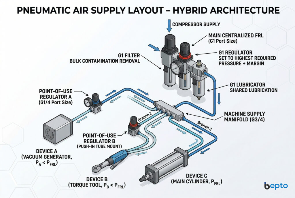
Hybrid Architecture — The Optimal Solution for Complex Machines
Most medium-to-high complexity machines benefit from a hybrid architecture that combines centralized FRL with point-of-use regulators:
Pneumatic Air Supply Layout
Centralized FRL Air Supply Layout
Hybrid architecture benefits:
- ✅ Single filter element for bulk contamination removal
- ✅ Single lubricator for all lubricated devices
- ✅ Individual pressure optimization per device
- ✅ Supply fluctuation isolation at each critical device
- ✅ Compressed air consumption minimized per device
- ✅ Maintenance concentrated at centralized FRL for filter and lubricator
Total Cost of Ownership — 3-Year Comparison
Scenario 1: Simple Machine — All Devices at Same Pressure
| Cost Element | Centralized FRL Only | Centralized + Point-of-Use |
|---|---|---|
| FRL unit cost | $ | $ |
| Point-of-use regulator cost | None | $$ (unnecessary) |
| Installation labor | $ | $$ |
| Maintenance (3 years) | $ | $$ |
| Process non-conformance | ✅ None — uniform pressure adequate | ✅ None |
| 3-year total cost | $$ ✅ | $$$ |
Verdict: Centralized FRL only — point-of-use adds cost without benefit.
Scenario 2: Multi-Pressure Machine (Mei-Ling’s Application)
| Cost Element | Centralized FRL Only | Centralized + Point-of-Use |
|---|---|---|
| FRL unit cost | $ | $ |
| Point-of-use regulator cost | None | $$ |
| Component damage (over-pressure) | $$$$ per month | None |
| Torque non-conformance rework | $$$$$ per month | None |
| Compressed air waste (over-pressure) | $$$ per month | ✅ 22% reduction |
| 3-year total cost | $$$$$$$ | $$$ ✅ |
Verdict: Point-of-use regulators pay back in < 3 weeks from damage and rework elimination alone.
Scenario 3: Pressure-Sensitive Process (Spray, Torque, Test)
| Cost Element | Centralized FRL Only | Point-of-Use at Critical Devices |
|---|---|---|
| Pressure stability at device | ±0.6 bar | ✅ ±0.03 bar |
| Process conformance rate | 78% (pressure variation) | ✅ 99.2% |
| Scrap and rework cost | $$$$$$ | $ |
| Customer returns | $$$$$ | None |
| Point-of-use regulator cost | None | $$ |
| 3-year total cost | $$$$$$$$ | $$$ ✅ |
At Bepto, we supply centralized FRL units in all port sizes (G1/8 through G1), miniature point-of-use regulators (G1/8, G1/4, push-in tube mount), precision regulators with ±0.02 bar hysteresis, regulator diaphragm and seat rebuild kits, and filter element replacements for all major pneumatic brand FRL and regulator products — with flow capacity, pressure range, and regulation accuracy confirmed for your specific application before shipment. ⚡
Conclusion
Map every pneumatic device on your machine against three parameters before specifying centralized or point-of-use regulation: the pressure each device requires, the pressure stability tolerance each device’s process demands, and the supply pressure variation each device will experience from distribution drops and shared demand fluctuations. Specify centralized FRL alone for machines where all devices operate at the same pressure within ±0.3 bar and where supply variation is acceptable at all devices. Specify point-of-use regulators at every device that requires a pressure different from the centralized supply, at every device whose process conformance requires tighter pressure stability than the centralized system provides, and at every device where over-pressure wastes compressed air at a rate that justifies the regulator cost within a reasonable payback period. The hybrid architecture — centralized FRL for filtration and lubrication, point-of-use regulators for device-level pressure control — delivers the maintenance simplicity of centralized treatment with the pressure independence of distributed regulation, and is the correct specification for the majority of medium-to-high complexity industrial machines. 💪
FAQs About Centralized FRL vs. Point-of-Use Regulators
Q1: My centralized FRL regulator has a stated accuracy of ±0.1 bar — why is the pressure variation at my downstream device greater than ±0.1 bar?
The regulator accuracy specification (±0.1 bar) describes the regulator’s output stability at its outlet port under steady-state flow conditions within its rated flow range. The pressure variation at your downstream device is the sum of the regulator accuracy plus the distribution pressure drop variation caused by changing flow rates in the tubing between the regulator and the device. If your device draws 100 Nl/min during actuation and near-zero flow at rest, the distribution tubing pressure drop changes by the full flow-dependent amount between these states — this variation is added to the regulator accuracy variation and is not controlled by the regulator. A point-of-use regulator installed at the device inlet eliminates the distribution drop variation because it regulates at the device, not at the machine inlet.
Q2: Can I use a point-of-use regulator to increase pressure above the centralized FRL set point for a specific device that requires higher pressure?
No — a standard pressure regulator can only reduce pressure below its inlet supply pressure. It cannot boost pressure above the supply. If a specific device requires higher pressure than the centralized FRL is set to, you must either raise the centralized FRL set point (which increases pressure to all devices) or install a pressure booster (intensifier) for that specific device. In practice, the correct approach is to set the centralized FRL to the highest pressure any device requires, then use point-of-use regulators to reduce pressure for all devices that require less — which is the hybrid architecture described in this article.
Q3: Are Bepto regulator rebuild kits compatible with both centralized FRL regulators and miniature point-of-use regulators of the same brand?
Bepto regulator rebuild kits are model-specific — the diaphragm, valve seat, and spring dimensions differ between centralized FRL regulators (which handle higher flow rates and use larger diaphragm assemblies) and miniature point-of-use regulators (which use smaller diaphragm and seat assemblies optimized for low flow and compact installation). Always specify the regulator brand, model number, and port size when ordering rebuild kits. Bepto’s technical team confirms the correct diaphragm material (NBR standard, EPDM for water service, FKM for chemical exposure), seat material, and spring rate for your specific regulator model before shipment.
Q4: How do I determine the correct set point for my centralized FRL when I am adding point-of-use regulators to an existing machine?
Set the centralized FRL to the highest point-of-use regulator set point plus the maximum distribution pressure drop plus the minimum differential pressure required by the point-of-use regulators (typically 0.5–1.0 bar). For example: if your highest point-of-use regulator is set to 5 bar, your maximum distribution drop is 0.3 bar, and your point-of-use regulators require 0.7 bar differential, set the centralized FRL to 5 + 0.3 + 0.7 = 6 bar. Verify this setting maintains adequate supply to all point-of-use regulators under worst-case simultaneous demand — measure the supply pressure at the furthest point-of-use regulator inlet during peak demand and confirm it remains above the regulator set point plus minimum differential.
Q5: My point-of-use regulator pressure is drifting upward over time without any adjustment — what is the cause and how do I restore stable regulation?
Upward pressure drift in a point-of-use regulator is almost always caused by a contaminated or worn valve seat that allows supply pressure to bleed through the closed valve into the regulated outlet — the regulator is no longer sealing completely, and supply pressure slowly raises the outlet pressure above the set point. This is the primary wear failure mode for miniature regulators in contaminated air systems. The correct repair is a regulator rebuild kit replacing the valve seat, diaphragm, and O-rings — Bepto rebuild kits restore factory sealing performance. To prevent recurrence, install a filter upstream of the point-of-use regulator if one is not already present — particulate contamination is the primary cause of valve seat wear in miniature regulators. ⚡
-
Explains the fundamental fluid dynamics equation used to calculate pressure drop in distribution tubing. ↩
-
Details the engineering methodology for calculating concurrent peak flow demand in automated machinery. ↩
-
Explores how electronic proportional technology achieves automated and highly accurate pressure profiling. ↩
-
Defines how mechanical hysteresis affects the accuracy and repeatability of pressure control valves. ↩
-
Provides industry data on energy losses and cost implications associated with over-pressurizing pneumatic systems. ↩
