

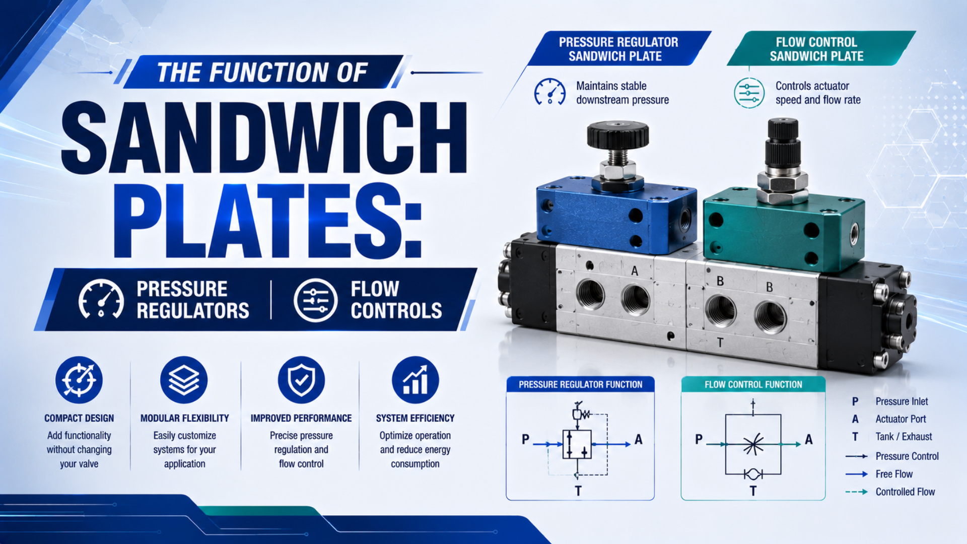
Pneumatic sandwich plates add pressure regulation, flow control, supply isolation, or another circuit function at one valve station without routing the station through a separate line-mounted device. Normally, the plate sits between the directional valve and its manifold or subbase. Its internal passages must match the valve interface, port function, pilot arrangement, and permitted stack order.
Compactness is useful, but it doesn’t make every plate interchangeable. “Sandwich plate” describes a mounting form, not one universal pneumatic circuit. Correct selection starts with the port that must be controlled, then checks the exact valve family and the manufacturer’s schematic.
Key Takeaways
- A sandwich plate changes one valve station while retaining a compact manifold layout.
- Common regulators control supply port 1; independent versions can regulate working ports 2 and 4 at the same station.
- Flow-control plates meter only the catalog-defined passages. They aren’t shut-off, isolation, load-holding, or safety devices unless the manufacturer explicitly assigns and rates one of those functions.
In this guide
- What does a pneumatic sandwich plate actually do?
- Which port does a pressure-regulator plate control?
- How do flow-control plates set cylinder speed?
- Stack order changes the pneumatic circuit
- Which interface standard applies?
- How should you size a plate for flow and pressure drop?
- What should you check before installation and commissioning?
- Common symptoms and diagnostic logic
- Pneumatic sandwich plate FAQs
What Does a Pneumatic Sandwich Plate Actually Do?
Festo’s ISO 5599-1 vertical-stacking guide shows a 43 mm regulator plate between the manifold subbase and solenoid valve; its flow-control plate occupies the same functional layer. This arrangement defines the basic role: add a local circuit function while preserving the valve station’s standardized port pattern (Festo Manifold Components, ISO 5599-1, 2008).
Pneumatic sandwich plates are ported modules clamped into a valve-to-subbase stack. Holes and seals continue selected supply, working, exhaust, and pilot passages through the assembly. Internal valves or restrictions then modify one or more of those passages before air reaches the directional valve or returns to the manifold.
The physical stack usually contains these layers:
- A directional valve switches air between supply, working, and exhaust ports according to its spool state and pilot arrangement.
- Approved functional plates modify selected passages.
- A manifold or individual subbase distributes air and provides external connections.
- The specified seals, studs, bolts, and any transition plates align and clamp the complete approved combination without blocking its internal galleries.
Standardized interfaces carry port geometry. Each plate, however, changes the circuit in a specific way. Pressure plates can regulate supply before the valve, regulate one working port after switching, or combine manufacturer-defined work-port functions; flow plates may throttle exhaust passages rather than the cylinder lines. Only the product symbol answers that question; the generic component name does not.
Interface compatibility and circuit compatibility are separate checks. Matching bolt holes and port positions can establish a mechanical interface, yet the assembly can still fail if a plate blocks pilot air, reverses a working-port function, uses the wrong gasket, or appears in an unapproved position.
Which Port Does a Pressure-Regulator Plate Control?
Parker’s ISO 15407-1 data distinguishes a common regulator from an independent dual-port regulator. Its common version regulates valve supply port 1 so working ports 2 and 4 receive the same pressure, while the independent version can regulate the two working ports separately (Parker Subbase and Manifold Valves Catalog, pages 67-68).
Regulator function depends on the force requirement in each motion direction:
| Regulator function | Controlled passage | Practical use | Selection caution |
|---|---|---|---|
| Common pressure | Supply port 1 | One reduced pressure for both valve work ports | Both directions share the same regulated supply |
| Port 2 regulator | Working port 2 | Local pressure limit in one switched path | Confirm which solenoid state connects supply to port 2 |
| Port 4 regulator | Working port 4 | Different pressure in the opposite path | Confirm port identity at the cylinder and valve |
| Independent dual-port | Ports 2 and 4 | Separate extend and retract pressure settings | Some designs reverse switching relationships |
| Reversible work-port regulator | Catalog-defined work port | Allows regulated forward flow and controlled reverse behavior | Not every plate is reversible or relieving |
Festo lists P, A, B, AB, and reversible A/B regulator plate variants in one ISO 5599-1 family. That variety matters. “Regulator plate” isn’t a complete specification, so an RFQ must name the regulated passage and state whether downstream pressure needs secondary relief. Pressure regulation changes available actuator force. It doesn’t create precision positioning by itself because position also depends on valve state, mechanical stops, sensing, load, friction, compressibility, and sometimes a closed-loop controller. See the double-acting cylinder operating guide for the interaction between its two working chambers. For the broader control distinction, compare proportional pressure regulation with ordinary mechanical regulation. Static gauge pressure doesn’t prove adequate dynamic performance either. At idle, a small regulator can show the correct pressure, then droop when the cylinder demands flow. Measure at the station during motion and use the product’s pressure-flow curve.
How Do Flow-Control Plates Set Cylinder Speed?
Festo assigns its VABF-S1 flow-control plate to exhaust ports 3 and 5. The catalog doesn’t present it as a generic restriction for every passage; it also identifies a 220 g plate on the ISO 5599-1 interface, so controlled ports and mechanical size both belong to the product definition (Festo Manifold Components, 2008).
Adjustable restrictions in one or more air paths allow a flow-control plate to change cylinder speed. Many use a check-valve bypass. Air then meets the restriction in one direction but passes more freely in reverse, provided the product schematic shows that path. The schematic determines whether the plate provides meter-in, meter-out, or common exhaust throttling.
| Flow-control location | Primary effect | Useful when | Main risk |
|---|---|---|---|
| Working port 2 | Controls the path connected to port 2 | One cylinder direction needs independent adjustment | Port mapping can reverse with valve configuration |
| Working port 4 | Controls the path connected to port 4 | Opposite motion needs a different setting | Do not assume port 4 always means extension |
| Exhaust ports 3 and 5 | Restricts exhaust leaving the valve | Compact station-level exhaust speed control | Shared exhaust backpressure may affect behavior |
| Supply port 1 | Restricts incoming supply | Specific low-load or fill-control circuits | Can reduce available force and make motion load-sensitive |
For many double-acting cylinder applications, controlled exhaust gives more stable motion because the exhausting chamber develops backpressure. That circuit principle isn’t permission to rotate or relocate any plate. See the meter-out control guide for the effect of load direction. Review the wider actuator speed-control workflow when tubing and valve flow also need adjustment. Don’t use a flow-control plate as a stop valve. Parker states that its ISO 15407-1 sandwich flow control is not a shut-off device and is not bubble-tight with the needles fully turned down. Closing the adjustment can slow motion dramatically while leakage still allows pressure equalization or cylinder creep.
Pressure and flow plates solve different control problems. A regulator limits the pressure available for force; a throttle sets the rate at which a chamber fills or exhausts. Combining them can tune force and speed at one station, but neither function alone certifies position holding, safe load support, or repeatable endpoint accuracy.
Stack Order Changes the Pneumatic Circuit
Parker permits both functions in one assembly. For the cited ISO 5599 and ISO 15407 families, however, its catalog requires the sandwich flow-control plate between the manifold or subbase and the common regulator; the approved stack order must therefore come from the selected manufacturer’s documentation (Parker Catalog, pages 54, 66 and 79).
Moving a plate changes circuit behavior. It can alter the pressure reaching a sensing element, the route by which regulated air exhausts, or the pilot galleries that remain supplied; an independent work-port regulator can also change the relationship between solenoid 12/14 actuation and ports 2/4. Review the assembled stack as one circuit.
Use this stack review before ordering:
- Match the complete valve family and station size.
- Trace ports 1, 2, 3, 4, 5, 12, and 14 through every layer on the manufacturer’s schematic, including any gallery that a plate blocks or redirects.
- Recheck internal or external pilot requirements after adding the regulator.
- Identify whether the regulator is relieving, non-relieving, or reversible, and document the consequence for trapped downstream pressure.
- Use the specified gasket and O-rings.
- Verify that the longer studs or bolts suit the complete stack, the approved tightening sequence is available, and the increased height fits the enclosure and cable routing.
- Confirm the number of permitted plates and their order.
Which Interface Standard Applies?
ISO 5599-1:2001 covers five-port pneumatic directional-valve mounting interfaces without an electrical connector and remains current after confirmation in 2024. ISO 15407-1:2000 covers smaller 18 mm and 26 mm five-port pneumatic interfaces, while ISO 4401:2005 applies to four-port hydraulic valves, not pneumatic valve stations (ISO 5599-1; ISO 15407-1; ISO 4401).
| Standard | Actual scope | What it can establish | What it does not establish |
|---|---|---|---|
| ISO 5599-1:2001 | Five-port pneumatic valve mounting interface without electrical connector | Interface dimensions, tolerances and port identification | Accessory stack order or cross-brand functional compatibility |
| ISO 15407-1:2000 | Five-port pneumatic interfaces in 18 mm and 26 mm sizes without electrical connector | Compact pneumatic mounting geometry and port interface | Pressure, flow, regulator accuracy or approved accessory mix |
| ISO 15407-2:2003 | Similar 18 mm and 26 mm pneumatic interface with optional electrical connector | Mechanical and optional electrical connector mateability | Complete valve-terminal compatibility |
| ISO 4401:2005 | Four-port hydraulic directional-valve mounting surfaces | Hydraulic mounting interchangeability within its scope | Pneumatic five-port manifold compatibility |
An interface standard is a necessary filter, not the entire selection. Manufacturers can offer different pilot arrangements, internal galleries, electrical architectures, station pitches, accessory codes, and permitted combinations on the same broad standard family. For a replacement request, record the valve and manifold part numbers, station size, electrical connection, pilot mode, port function, existing plate code, pressure range, and required flow. Photos of the top and side labels help, but a pneumatic schematic or assembly drawing is more decisive.
How Should You Size a Plate for Flow and Pressure Drop?
ISO 6358-1:2013 excludes internally fed-back regulators from its scope. For a throttle plate with a fixed or variable internal path, use an applicable steady-state conductance or flow curve under the standard’s stated conditions; for a regulator, use the manufacturer’s pressure-flow or droop curve instead (ISO 6358-1, confirmed 2022).
Start with the actuator’s required flow at its working pressure and target stroke time. Then follow the complete path through the manifold, sandwich plates, directional valve, fittings, tubing, and exhaust devices. Whichever passage has the smallest effective area can limit speed even when every individual component appears adequately sized. Don’t select from a “maximum flow” number without its test condition. Record at least:
- inlet and outlet pressure;
- allowable differential pressure and the consequence of exceeding it;
- flow reference conditions, unit conversions, reference temperature and pressure, test direction, valve position, and the catalog method used to derive the published value;
- direction of flow through each controlled port;
- regulator set pressure and the maximum permitted droop during actuator demand;
- throttle setting;
- exhaust silencer, tubing, downstream restrictions, and any shared exhaust path;
- required cylinder speed under the actual load and supply condition.
Parker publishes separate Cv paths for common, single-port, and dual-port regulator configurations, with different values for paths such as 1-to-2 and 2-to-3. This is why one generic flow-capacity number cannot describe an entire plate. The pneumatic flow-control overview and choked-flow guide provide the surrounding sizing context.
Dynamic measurements separate pressure and flow faults. Correct static pressure followed by a large pressure drop during motion points toward insufficient conductance, regulator droop, restricted exhaust, or inadequate supply. Stable dynamic pressure with incorrect force points instead toward cylinder area, friction, load, leakage, or mechanical alignment.
What Should You Check Before Installation and Commissioning?
ISO 4414:2010 addresses pneumatic-system hazards and applies to assembly, installation, adjustment, operation, maintenance, reliability, and energy efficiency. It does not provide one universal sandwich-plate torque value; safe commissioning therefore combines the machine’s risk controls with the selected manufacturer’s assembly instructions (ISO 4414, confirmed 2021).
Use a controlled installation sequence:
- Isolate both energy sources, vent stored pressure, and secure movable loads.
- Verify the valve, manifold, functional plate, gasket, seal, stud, and bolt part numbers against the complete assembly documentation before separating the existing stack.
- Inspect mating faces and grooves.
- Remove particles without scratching a sealing surface, then confirm that every seal matches its documented groove and material specification.
- Orient each plate by its port symbol and locating features, never by adjustment-knob direction alone.
- Install only the specified fasteners and seals. Apply the documented torque, tightening sequence, lubrication, and thread treatment.
- Restore pressure gradually.
- Start regulator adjustment from a low safe setting, restrict initial cylinder speed, and confirm pilot supply before commanding a full stroke.
- Test valve shifting, pressure regulation, extend speed, retract speed, and exhaust behavior separately.
- Check external leakage, then measure pressure during motion rather than accepting only a static gauge reading.
- Record final settings, part numbers, station position, supply condition, load, and acceptance results for maintenance.
Treat a suspended or overrunning load separately. Pneumatic compressibility and normal component leakage can allow motion even when a directional valve or throttle appears closed. If unexpected motion creates a hazard, use an engineered load-restraint or safety function validated for that risk, not an ordinary sandwich flow control. Avoid universal assembly shortcuts: generic bolt torque, unapproved thread locker, an added gasket, or a reused damaged O-ring can distort the stack or block a passage. Use the actual valve-terminal documentation for the correct value.
Common Symptoms and Diagnostic Logic
Parker gives a direct limitation: this plate isn’t a shut-off device. Its ISO 15407-1 catalog also says the sandwich flow control isn’t bubble-tight when fully turned down, which explains why slow leakage needn’t indicate a failed new plate and why the throttle can’t serve as a safe isolation function (Parker Catalog, page 66).
| Symptom | First checks | Why it points there |
|---|---|---|
| Both cylinder directions have low force | Common regulator setting, inlet pressure, dynamic droop, supply port 1 | Both work ports depend on the shared regulated supply |
| Only one direction has low force | Port 2/4 regulator selection, cylinder hose mapping, valve state | Independent regulation acts on a specific switched path |
| Static pressure is correct but falls during motion | Regulator flow curve, plate conductance, valve, tubing and exhaust restriction | Demand exposes pressure loss that an idle gauge cannot show |
| One adjustment changes the wrong direction | Plate symbol, work-port mapping, solenoid 12/14 relationship | Port relationships can differ with valve and regulator configuration |
| Cylinder creeps with the throttle closed | Normal non-bubble-tight throttle behavior, valve leakage, external load | A speed-control needle is not an isolation valve |
| Valve does not shift after adding a regulator | Internal/external pilot configuration and pilot galleries | The regulator stack may alter the pressure feeding pilot ports |
| External leak begins after assembly | O-ring position, gasket compatibility, surface damage, fastener kit | A mechanical sealing fault often appears immediately after stacking |
| Both directions are slow | Exhaust flow control, silencers, common restriction, undersized path | A shared restriction can affect both cylinder chambers |
Change one variable at a time. Record the initial state, identify the affected port, and test the station under the same load and supply condition after each correction. Otherwise several simultaneous adjustments can hide the actual fault. If debris or degraded lubricant repeatedly changes a needle or regulator response, treat the air-quality cause separately with the control-valve contamination workflow. Replacing a plate without removing the contaminant only resets the failure cycle.
Pneumatic Sandwich Plate FAQs
Festo lists P, A, B, AB, and reversible regulator variants. Parker separately documents common and independent regulators, reinforcing a practical FAQ rule: identify the controlled port, exact valve family, pilot arrangement, and approved stack before treating two similarly named plates as equivalent (Festo, 2008; Parker).
Are pneumatic sandwich plates universally interchangeable?
No. An ISO interface can align mounting surfaces and ports within its scope, but it does not approve every accessory combination. Confirm the valve family, station size, electrical interface, pilot arrangement, port schematic, seals, fasteners, plate order, and manufacturer compatibility statement before substituting a plate.
Does a pressure-regulator plate improve cylinder positioning accuracy?
Not by itself. The regulator stabilizes or limits pressure, which affects available cylinder force. Position accuracy also depends on sensing, valve control, mechanical stops, friction, load variation, air compressibility, and the control strategy. Use closed-loop or mechanically defined positioning when the application requires a measured position tolerance.
Should a flow-control plate restrict supply or exhaust?
It depends on the plate and load. Many cylinder circuits use meter-out control for stable motion, and some manifold plates specifically restrict exhaust ports 3 and 5. Other products control working or supply passages. Follow the plate symbol and application data rather than inferring the path from its mounting orientation.
Can a sandwich flow-control plate hold a cylinder safely?
No ordinary throttle should be credited as a safety holding device. Parker states that one sandwich flow-control family is not a shut-off and is not bubble-tight when fully closed. Pneumatic leakage, compressibility, valve leakage, and external load can still produce movement, so hazardous loads need a validated restraint.
Can a regulator and flow-control plate be stacked together?
Sometimes. Parker permits this combination in specific ISO valve families but requires the flow-control plate between the manifold or subbase and the common regulator. Other products can use different rules. Verify the approved combination, plate order, pilot supply, fastener kit, pressure rating, and resulting flow before assembly.
Sources
- Festo Manifold Components, ISO 5599-1, regulator, flow-control, supply and shut-off plates for vertical stacking. Retrieved 2026-07-22.
- Parker Subbase and Manifold Valves Catalog 0600P-E, ISO 5599 and ISO 15407 sandwich regulator, flow-control, pilot and stacking data. Retrieved 2026-07-22.
- ISO 5599-1:2001, five-port pneumatic directional-valve mounting interfaces without electrical connectors. Retrieved 2026-07-22.
- ISO 15407-1:2000, 18 mm and 26 mm five-port pneumatic mounting interfaces without electrical connectors. Retrieved 2026-07-22.
- ISO 15407-2:2003, 18 mm and 26 mm pneumatic interfaces with optional electrical connectors. Retrieved 2026-07-22.
- ISO 4401:2005, four-port hydraulic directional-valve mounting surfaces. Retrieved 2026-07-22.
- ISO 6358-1:2013, steady-state flow-rate testing scope for pneumatic components. Retrieved 2026-07-22.
- ISO 4414:2010, pneumatic-system safety requirements covering assembly, installation, adjustment and maintenance. Retrieved 2026-07-22.