

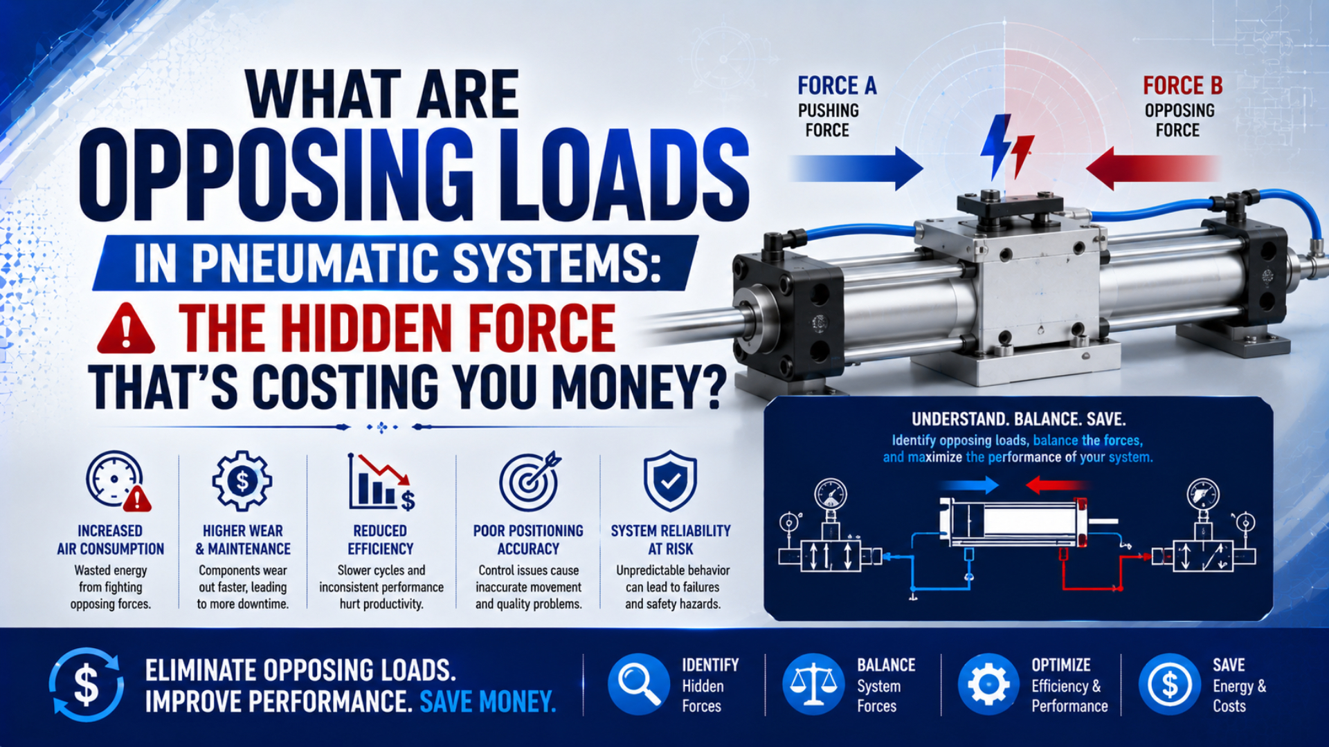
An opposing load is a force that acts against a pneumatic actuator in the direction being evaluated. It can come from the work itself, gravity, friction, a spring, acceleration, exhaust back pressure, or a combination of these effects. If one term is omitted, a cylinder that looks adequate on paper may move slowly, stall, or require more pressure than expected.
The important word is direction. Gravity opposes an upward stroke but assists a downward stroke. A spring may resist extension and assist retraction. Friction reverses with motion. Back pressure depends on which chamber is exhausting. There is no defensible rule that converts every opposing load into one fixed pressure increase or one universal percentage of rated cylinder force.
Key Takeaways
- Start with a free-body diagram for one stroke direction, not a generic list of loads.
- Add process force, gravity, friction, spring force, inertia, and exhaust-side resistance only when they oppose that movement.
- Use pressure measured at the cylinder during motion and the correct extension or retraction area.
- Apply the selected cylinder series’ load ratio, moment, speed, and energy limits instead of inventing a universal margin.
- Fix restrictions and load-path errors before raising plant pressure or increasing bore.
What Counts as an Opposing Load?
An opposing load is any force component whose vector points against the actuator’s intended motion. NASA’s explanation of Newton’s second law notes that force and acceleration are vector quantities and can be resolved by direction; this is the correct starting point for a pneumatic load budget (NASA Glenn Research Center).
That definition prevents two common errors. First, do not count the same physical demand twice. For a cylinder lifting a freely suspended mass, its weight is the application load in the upward direction; “application load plus gravity” would duplicate the same force unless the application load means a separate process force. Second, do not assume a force is always unfavorable. The same spring or gravitational term can change sign when the cylinder reverses.
Build a separate list for extension and retraction:
| Load component | How to quantify it | Direction check |
|---|---|---|
| Process force | Measured or specified force at the tool or workpiece | Does the process push back during this stroke? |
| Gravity | Mass multiplied by gravitational acceleration and the component along the motion axis | Does the axis move up, down, or on an incline? |
| Sliding or guide friction | Measured breakaway and running resistance, or approved design data | Friction opposes the current direction of motion |
| Spring force | Spring rate multiplied by displacement within the spring’s valid range | Does the spring resist or assist this stroke? |
| Inertia | Moving mass multiplied by commanded acceleration | Acceleration and deceleration can reverse the force direction |
| Exhaust back pressure | Exhaust-chamber pressure multiplied by its effective area | Which chamber is exhausting during this stroke? |
| External moment or side load | Force multiplied by offset, then checked against guide ratings | Is thrust being converted into bearing friction or binding? |
OpenStax describes friction as a force that opposes motion or its tendency and spring force as a restoring force proportional to displacement and opposite to that displacement (OpenStax, Common Forces). Those definitions explain why fixed “friction percentage” and “spring pressure factor” tables are weak substitutes for actual inputs.
How Do You Build a Directional Force Budget?
A directional force budget puts every force on one axis, assigns a sign, and calculates the remaining force available to accelerate or do useful work. For an extension stroke, a practical form is:
For retraction, pressure acts on the annular area and the cap-end pressure can oppose it:
The two effective areas are:
Here, is bore diameter and is rod diameter. Use consistent units: pascals with square metres produce newtons, while megapascals with square millimetres also produce newtons. Festo’s pneumatic-actuator training material uses pressure times piston area for theoretical force and warns that real force is lower because of internal friction and external side loading (Festo Didactic).
SMC’s air-cylinder selection guide makes the same practical distinction. It says seal and bearing resistance must be subtracted even at rest, and exhaust pressure also acts during operation. It further notes that the single-rod retraction area is reduced by the rod cross-section (SMC Air Cylinders Model Selection).
Do not apply both a blanket “efficiency factor” and separately measured friction and back pressure unless the selected method explicitly requires both. That would hide or double-count the same losses. Our detailed guide to cylinder force loss from friction and back pressure covers the chamber-pressure calculation in more depth.
Calculating Each Opposing Force
Each force needs its own input and operating point. A single percentage cannot represent a spring whose force changes through the stroke, a guide that has different breakaway and running friction, and a mass that changes inertial demand with the motion profile.
Gravity and acceleration
For vertical upward motion, the gravitational term is . If the moving mass is also accelerating upward, the inertial term is . NASA gives the constant-mass relation and explains that direction is part of the force vector (NASA Glenn Research Center).
On an incline at angle from horizontal, the gravity component along the axis is . Confirm how the angle is defined before using a drawing or calculator. For a complete vertical-lift bore calculation, use our vertical-up cylinder sizing guide.
Spring resistance
For a linear spring operating inside its specified range, the force magnitude is , where is spring rate and is displacement from the relaxed position. Spring force therefore changes through the stroke. Use the worst relevant position, not an average that misses peak demand. OpenStax identifies this proportional restoring-force relationship as Hooke’s law (OpenStax).
Gas springs, Belleville washers, elastomer stacks, toggles, and over-centre mechanisms may not follow a simple linear relationship. Use their force-displacement data or measure the mechanism through its complete travel.
Friction and breakaway force
Friction should be separated into breakaway, running, and guide-related resistance when the application is sensitive to low speed or small force margins. Seal friction changes with bore, pressure, seal design, lubrication, temperature, wear, and dwell. External guide friction also changes with alignment and moment load.
Measure force or infer it from controlled pressure tests when catalog data are insufficient. A calculated running force can still fail to start the load if breakaway resistance is higher. Record the two values separately instead of hiding both inside one friction allowance.
Back pressure and restrictions
Back pressure is an opposing pneumatic force, not a percentage to add to the supply-pressure requirement. Multiply the measured pressure in the exhausting chamber by that chamber’s effective area, then subtract the result in the force balance.
Measure while the problem occurs. A regulator gauge can look healthy after the cylinder stops even though the supply chamber lost pressure or the exhaust chamber built pressure during motion. CAGI states that pressure drop occurs through piping, fittings, filters, dryers, and other components, and advises against increasing compressor discharge pressure as the first response to excessive point-of-use pressure loss (CAGI Pressure Drop Technical Brief).
Worked Example: A Spring-Loaded Horizontal Slide
This hypothetical calculation shows how several modest forces can combine into one material opposing load. It is not a customer case or a universal sizing recommendation.
A cylinder extends a horizontal slide while compressing a linear spring. The design inputs at the most demanding point are:
| Input | Example value |
|---|---|
| Required process force | 180 N |
| Measured running friction | 70 N |
| Spring rate | 12 N/mm |
| Spring compression | 20 mm |
| Moving mass | 15 kg |
| Extension acceleration | 0.8 m/s² |
| Equivalent exhaust back-pressure force | 45 N |
| Dynamic cap-end pressure | 0.6 MPa |
The spring force is , and the inertial term is . The total opposing force at that point is therefore:
A 40 mm bore has a theoretical extension force of approximately 754 N at 0.6 MPa. The example load ratio is therefore about 0.73. In the cited SMC CJ2/CM2 selection guide, the recommended load ratio is 0.7 or below for stationary operation and 0.5 or below for dynamic operation. Those are manufacturer selection values for the covered cylinders, not universal pneumatic limits. Under that guide’s dynamic criterion, the 40 mm option is not adequate.
A 50 mm bore produces approximately 1,178 N theoretically at the same pressure, giving an example load ratio of about 0.46. That clears the cited 0.5 criterion, but selection is still incomplete: confirm the exact series, available pressure through the stroke, speed, cushion or external stop, mounting, guide load, and force variation. Parker’s cylinder sizing tool likewise asks for load weight, orientation, acceleration or deceleration, friction, back pressure, available pressure, mounting, and stroke rather than one generic opposing-load factor (Parker Cylinder Sizing Tools).
If the total required load is already known and bore is the unknown, the Cylinder Bore Size Calculator provides a useful preliminary check. Final selection must still follow the exact manufacturer’s catalog.
Why Does Ignoring Opposing Load Increase Operating Cost?
An incomplete load budget creates cost through wrong corrective actions. An undersized actuator may stall or miss cycle time. A larger-than-needed bore consumes more swept air each cycle. Raising system pressure to hide a restriction increases the pressure carried by other components and can increase demand through leaks. Misalignment can turn useful thrust into guide friction while accelerating bearing and seal wear.
The remedy is not automatically “more pressure” or “a rodless cylinder.” First identify where the force is going:
- Record extension and retraction symptoms separately.
- Measure both cylinder-port pressures during the affected movement.
- Disconnect the load where the machine’s safe procedure permits, then compare actuator and mechanism resistance.
- Measure breakaway and running resistance through the stroke.
- Check spring or process-force curves at the highest-demand position.
- Verify speed, acceleration, cushion, and stopper conditions.
- Inspect alignment, guide preload, load offset, and mounting compliance.
In our experience, we use this sequence before recommending a larger bore or higher pressure. It distinguishes a genuine force shortage from a valve, tube, muffler, guide, or mechanism problem. CAGI specifically recommends addressing pressure-drop causes rather than making higher compressor pressure the first response.
Which Cylinder Type Should Handle the Load?
Cylinder architecture should be selected from the load path, stroke, guidance, moment, speed, and required force, not from the phrase “high opposing load” alone.
| Application condition | Selection direction |
|---|---|
| Axial push or pull with an externally guided load | Standard rod cylinder may be appropriate after bore, rod, mount, and buckling checks |
| Load offset creates pitch, yaw, or roll moment | Use a guided cylinder or external linear guide with published moment ratings |
| Long travel with limited installation length | A rodless cylinder may solve packaging and extended-rod buckling concerns |
| Vertical load must remain controlled after air or power loss | Use a validated safety architecture; ordinary cylinder thrust is not a holding guarantee |
| High end-of-stroke energy | Check cushion capacity or add a correctly sized external shock absorber |
Rodless does not mean unlimited side-load capacity. SMC’s MY1B catalog requires checks for maximum load, static moment, and dynamic moment at stopper impact; it combines those guide load factors and requires their sum to remain within the catalog limit (SMC MY1B Catalog). Review rodless cylinder load-capacity myths and linear-actuator side loading before treating carriage load as usable thrust.
For vertical axes and other hazardous movements, force sizing is only one part of machine safety. ISO 4414 covers general rules and safety requirements for pneumatic systems and components on machinery, including reliable operation and significant pneumatic hazards (ISO 4414:2010). A directional valve, trapped air, a counterbalance circuit, or an ordinary rod lock should not be assumed to create a safety function without a risk assessment and validated control architecture.
What Data Should Go Into the Cylinder RFQ?
A useful RFQ separates force demand from component preference. Send enough information for the supplier to reproduce the directional load budget:
- required process force and where it acts;
- moving mass, orientation, incline angle, and centre-of-gravity offset;
- extension and retraction directions that do useful work;
- target stroke, time, speed, acceleration, deceleration, and cycle rate;
- spring, cam, toggle, or clamp force through the full travel;
- measured breakaway and running resistance, if available;
- minimum dynamic pressure at both cylinder ports;
- valve, tube, fitting, silencer, and flow-control details;
- bore, rod diameter, mounting, and guidance for a replacement cylinder;
- external moments, end-stop method, and cushion requirement;
- safe state after loss of air, electrical power, or control signal.
Do not send only mass and plant pressure. Those two values cannot reveal whether the load is guided, whether retraction does the work, whether a spring peaks near the end of travel, or whether exhaust back pressure consumes the available force.
FAQs About Opposing Loads in Pneumatic Systems
SMC’s selection guide explicitly subtracts seal, bearing, and exhaust-pressure resistance from useful cylinder force, while Parker’s sizing tool asks for orientation, motion, friction, back pressure, and available pressure. Together, those manufacturer resources show why opposing load must be evaluated by direction and operating condition rather than a universal percentage.
What is an opposing load in a pneumatic system?
An opposing load is any force component acting against the movement being evaluated. It can include process force, gravity, friction, spring force, inertia, exhaust back pressure, or resistance created by an offset load. The same force may assist the reverse stroke, so extension and retraction need separate force budgets.
Is back pressure an opposing load?
Yes. Pressure in the exhausting chamber acts on that chamber’s effective area and subtracts from drive-side force. Measure both cylinder ports during the affected stroke, calculate the two pressure-area forces separately, and do not subtract back pressure from supply pressure unless both pressures act on the same effective area.
How much safety margin should be added for opposing loads?
There is no universal margin for every cylinder and motion profile. Use the selected manufacturer’s load-ratio or sizing method and verify pressure variation, friction, speed, energy, mounting, and safety requirements. For example, the cited SMC CJ2/CM2 guide uses load ratios of 0.7 or below for stationary operation and 0.5 or below for dynamic operation.
Can higher pressure solve an opposing-load problem?
Higher pressure increases theoretical force only when it reaches the driving chamber and remains within every component rating. It does not correct binding, side load, an undersized exhaust path, or a wrong force direction. Measure dynamic port pressures and correct restrictions or mechanical resistance before changing plant pressure.
Do rodless cylinders handle opposing loads better than rod cylinders?
Not automatically. A rodless cylinder can provide long travel without an extending piston rod, but its carriage still has published load and moment limits. Choose between rod, guided, and rodless designs by checking axial force, stroke, packaging, guidance, static moment, dynamic moment, speed, and end-of-stroke energy.
Sources and technical references
-
SMC, Air Cylinders Model Selection, bore size and load ratio guidance. Evidence role: piston and annular area, seal and bearing resistance, exhaust-pressure resistance, and series-specific load-ratio guidance. Retrieved 2026-07-22.
-
Festo Didactic, Mechatronics: Pneumatics. Evidence role: theoretical pressure-area force and reduction of real force by internal friction and external side loading. Retrieved 2026-07-22.
-
Parker, Basic Cylinder Sizing Tools. Evidence role: orientation, load motion, friction, back pressure, available pressure, bore, mounting, and stroke inputs. Retrieved 2026-07-22.
-
Compressed Air and Gas Institute, Technical Brief on Pressure Drop. Evidence role: pressure-drop causes, point-of-use pressure, and corrective actions before raising compressor pressure. Retrieved 2026-07-22.
-
SMC, MY1B Mechanically Jointed Rodless Cylinder Catalog. Evidence role: maximum load, static moment, dynamic moment, and combined guide load-factor checks. Retrieved 2026-07-22.
-
NASA Glenn Research Center, Newton’s Second Law of Motion. Evidence role: force as mass times acceleration for constant mass and directional vector treatment. Retrieved 2026-07-22.
-
OpenStax, University Physics Volume 1, Common Forces. Evidence role: friction direction and the spring restoring-force relationship. Retrieved 2026-07-22.
-
ISO 4414:2010, Pneumatic fluid power: General rules and safety requirements for systems and their components. Evidence role: pneumatic-system safety scope and reliable operation requirements. Retrieved 2026-07-22.