

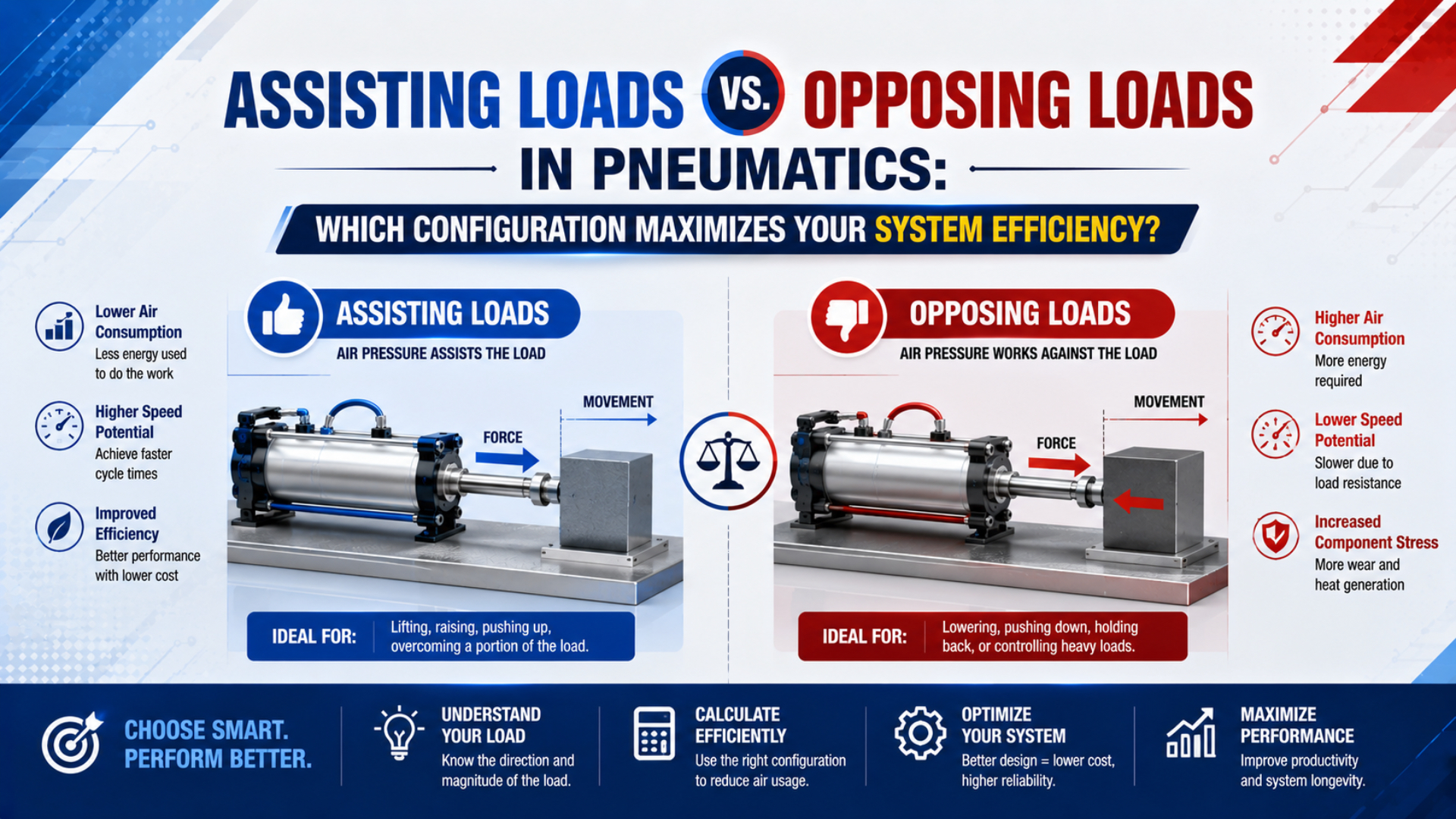
Assisting loads vs opposing loads in pneumatics do not produce a universal efficiency winner. Classify external forces separately for each stroke. Then calculate pressure force from both cylinder chambers and select the bore, flow control, guidance, cushioning, and load-holding method from the resulting net force.
SMC varies load-rate limits by task. For many vertical and horizontal dynamic-load cases, its cylinder model-selection guide uses 0.5 or less. This application-specific ceiling does not prove that one load direction always saves a fixed percentage of pressure (SMC Air Cylinder Model Selection, accessed 2026-07-22).
Key Takeaways
- Classify every load separately for extension and retraction.
- Use both cylinder-port pressures in the force balance during motion.
- A gravity-assisted stroke may need more exhaust control and a separately engineered holding method even when it needs less driving force.
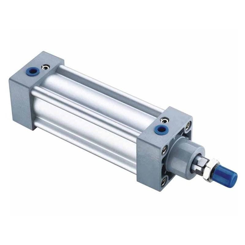
A single-rod cylinder has a full piston area on the cap side and a smaller annular area on the rod side. Both chamber pressures can act during motion.
Assisting and Opposing Describe Force Direction, Not Cylinder Type
SMC separates extension and retraction before bore selection. Effective areas differ, so designers must identify the direction in which cylinder force will be used. Apply the same discipline to external load by comparing it with commanded movement for every stroke instead of labeling the machine once (SMC Air Cylinder Model Selection, accessed 2026-07-22).
Assisting load means an external force acts in the commanded travel direction. Gravity assists a downward-moving vertical carriage, a spring can help open a gate, and a linkage can pull a cylinder through part of its stroke. Such force adds to the actuator’s tendency to move. Opposing load means the force acts against commanded travel. Gravity opposes an upward lift; clamp reaction and guide friction can do the same. The cylinder must overcome this resistance before any margin remains for acceleration.
Overrunning load describes an assisting load strong enough to move the mechanism ahead of controlled air supply, making starting pressure and stable motion separate circuit questions.
Classify every meaningful external force on a load sketch:
- Mark one positive travel direction.
- Draw gravity, springs, process reactions, guide friction, counterweights, and any force transmitted by the machine linkage.
- Resolve angled forces along the cylinder axis.
- Repeat the sketch for the return stroke and at intermediate positions whenever a spring, cam, lever, or toggle changes force magnitude or direction.
Counterweights show why one label can mislead: the same weight may oppose downward travel yet assist upward travel. Toggle mechanisms can reverse the relationship within one stroke. Calculate every position where force magnitude or direction changes materially.
Calculate Net Cylinder Force From Both Chambers
AutomationDirect calculates cylinder force from area and differential pressure. Its sizing reference also subtracts rod area on retraction. Machine-level analysis should additionally keep both port pressures, signed external forces, and friction visible instead of burying unrelated effects in one percentage allowance (AutomationDirect Cylinder Sizing, accessed 2026-07-22).
For a single-rod cylinder, let represent bore diameter and represent rod diameter when calculating full piston area and rod-side annular area :
With rod-out travel defined as positive, use this first-pass extension net-force equation:
is cap-end pressure during motion, is rod-end pressure during motion, and represents seal, guide, and mechanism friction opposing travel. Use absolute force directions consistently. Do not insert the regulator setting for both pressures.
For retraction, reverse the positive direction and use the correct working areas:
Pressure in MPa multiplied by area in mm² produces force in newtons; one bar equals 0.1 MPa, or 0.1 N/mm². Available acceleration before other dynamic effects is . A positive result alone does not approve the cylinder. Remaining margin must cover pressure variation, breakaway friction, speed, impact, and the selected manufacturer’s load-rate rule.
Treat measured chamber pressure as an operating-state variable, not a nameplate property. Record both port pressures at the same piston position and load condition because a supply-side gauge cannot reveal exhaust back pressure. Build one signed equation for each motion direction, then solve it at startup, mid-stroke, peak process force, and cushion entry. If a spring or linkage changes force with position, add operating points instead of averaging the load. Apply one catalog-backed load rate only after the physical forces are visible. Finally, verify the candidate with its actual rod diameter, minimum working pressure, speed range, guide limits, cushion capacity, and permitted mounting orientation. This sequence separates measurable forces from selection allowances and prevents the same uncertainty from being counted twice. Acceptance testing must reproduce the documented worst cases.
This calculator supplies a preliminary pressure-area result, but it cannot know whether gravity assists the stroke, a spring reverses direction, or the exhaust path creates substantial back pressure. Keep those terms on the worksheet. For the next step after required force is known, use the cylinder bore sizing guide.
Worked Example: One Vertical Load, Two Different Force Conditions
AutomationDirect’s force relation uses differential pressure, while SMC instructs designers to select extension and retraction separately. Consider a 50 mm bore cylinder with a 20 mm rod: its full piston area is about 1,963 mm², but rod-side working area is only about 1,649 mm² (AutomationDirect; SMC, accessed 2026-07-22).
Assume the cylinder is mounted vertically with the rod pointing down and carries a 40 kg guided mass. Use 5.5 bar in the driving chamber and a measured 1.0 bar in the exhausting chamber during motion. Gravity contributes approximately:
During downward extension, cap-end pressure drives the load and gravity assists it:
During upward retraction, rod-end pressure drives the load while cap-end back pressure and gravity oppose it:
Both results omit friction and therefore remain calculation margins, not permissible payload ratings.
| Stroke | Driving pressure force | Exhaust-side pressure force | Gravity | Net before friction |
|---|---|---|---|---|
| Extend downward | 1,080 N downward | 165 N upward | 392 N downward | 1,307 N downward |
| Retract upward | 907 N upward | 196 N downward | 392 N downward | 319 N upward |
More force is available on the downward stroke, but control and efficiency do not follow automatically. Unrestricted exhaust may allow excessive acceleration. By contrast, the upward stroke has much less margin and greater sensitivity to supply sag, exhaust restriction, seal friction, and payload variation.
Change one condition at a time when reviewing the design:
- Replace every assumed pressure with the lowest measured driving-port pressure and the corresponding exhaust-port pressure during the demanding part of each stroke.
- Test both payload extremes.
- Add acceleration and process forces where they peak.
- Apply one documented manufacturer load-rate or application factor instead of stacking several unrelated percentages that cover the same uncertainty.
- Select the next catalog bore, then repeat both directional calculations with its actual rod diameter and catalog limits.
Replace the “assisting versus opposing pressure percentage” comparison with a force-margin profile that can expose generous starting force, poor mid-stroke margin, and an overrunning condition near the end as linkage geometry changes.
Why an Assisting Load Can Need More Motion Control
SMC describes exhaust-port control as the most common way to regulate cylinder speed because changing exhaust back pressure changes piston velocity. Its published speed relation also assumes constant inlet pressure, so it cannot by itself predict a vertical axis whose load drives the piston ahead of the supplied flow (SMC Control Air Flow, accessed 2026-07-22).
Meter-out control restricts air leaving the non-driving chamber. Restricting exhaust raises back pressure, resists motion, and can stabilize a gravity-assisted or spring-assisted stroke. Back pressure also subtracts from net cylinder force; measure both ports before opening the controller or raising supply pressure. Meter-in control instead restricts air entering the driving chamber. It can suit a predictable resisting load, but an overrunning load may pull the mechanism ahead as driving pressure falls. Resulting motion can alternate between surging and stalling.
Use the meter-in versus meter-out engineering guide for valve orientation and commissioning while keeping the following four load-analysis functions separate:
| Function | Typical method | Engineering boundary |
|---|---|---|
| Normal travel speed | Meter-in or meter-out flow control | Does not prove adequate force or safe holding |
| Controlled startup | Soft-start or staged speed controller | Does not control every loss-of-pressure event |
| Temporary pneumatic stop | Pilot-operated check arrangement | Leakage and hose failure still require review |
| Safety-related load holding | Risk-assessed brake, lock, or mechanical restraint | Must match the machine’s required safety function |
SMC’s ASS valve changes from meter-in during initial pressurization to ordinary meter-out after the cylinder is pressurized, demonstrating through its architecture that startup behavior and normal travel control are different design states (SMC ASS, accessed 2026-07-22).
For drop prevention, SMC separately offers end locks, locking cylinders, pilot-check speed controllers, and double-check arrangements. Standard speed controllers are therefore not positive load-holding devices (SMC Drop Prevention, accessed 2026-07-22). ISO 4414 remains the general pneumatic-system safety standard and addresses significant hazards, reliable operation, and energy efficiency at the system level (ISO 4414:2010, confirmed 2021).
Evaluate a vertical or spring-assisted axis in four states: initial pressurization, normal travel, commanded stop, and loss of pressure. Normal meter-out adjustment may stabilize travel but says nothing about the force that appears before both chambers are pressurized. A pilot-check arrangement can provide a temporary pneumatic stop, yet leakage, hose failure, trapped energy, and manual pressure release still require analysis. Where falling or unexpected movement can create a hazard, define the required safety function first and choose a lock, brake, mechanical restraint, or validated pneumatic architecture accordingly. Test each state with the lightest and heaviest approved payloads. Record restart behavior after every stop because a cylinder that holds acceptably can still jump when pressure is restored. Flow control, holding, isolation, and emergency behavior should never be collapsed into one valve setting.
Which Configuration Uses Less Compressed Air?
SMC’s model-selection procedure includes separate air-consumption and required-air-volume checks after the bore and operating pressure are chosen. This ordering matters: assisting load direction alone does not determine consumption. Bore, stroke, regulated pressure, dead volume, cycle rate, valve state, leakage, and exhaust strategy all contribute (SMC Air Cylinder Model Selection, accessed 2026-07-22).
Driving pressure can fall on an assisted stroke only when all of the following are true:
- Pressure is actually regulated lower at the actuator.
- Stable motion remains possible across the complete payload range plus the expected temperature, seal-friction, guide-friction, and supply-pressure variations documented for the machine.
- Required exhaust back pressure does not erase the reduction.
- Cylinder bore remains appropriate for the opposite stroke.
- Cushioning, stopping, restart behavior, and the risk-assessed load-holding function all remain acceptable after the pressure change.
If the regulator remains at the same setting and the same cylinder volume is charged every cycle, gravity does not automatically create an air saving. It may simply increase acceleration and the energy that cushioning or an external shock absorber must absorb.
Opposing force may require more pressure, more piston area, or different mechanical advantage, and each choice has a different energy consequence. Raising plant pressure affects other consumers; choosing a larger bore increases charged volume every cycle. Mechanical changes such as counterweights, spring balances, or separate lift mechanisms can reduce actuator force without raising system pressure, but they add safety and maintenance checks of their own.
Use this comparison sequence:
- Calculate net force in both directions at every worst operating position identified on the load sketch.
- Choose the smallest standard actuator that passes.
- Calculate complete-cycle air demand at the intended regulated pressure, including tubing or other repeatedly charged dead volume when it is material.
- Measure dynamic port pressure and standard air flow.
- Compare alternatives only after they deliver the same safe motion, payload range, stopping behavior, and required cycle time.
In our experience reviewing applications, the most useful measurement is rarely compressor-room pressure. A synchronized trace of both cylinder-port pressures and stroke position shows whether a weak stroke comes from external load, supply loss, exhaust back pressure, changing linkage angle, or friction near one point in travel.
Rodless Cylinders Change the Load Path, Not the Force Rules
Parker conditions its basic OSP-P load data on speed. At no more than 0.5 m/s, designers must still check load, force, moment, and cushion performance. Removing an exposed piston rod avoids that rod’s compression-buckling limit, but it cannot remove carriage-guide reactions or the energy that the axis must absorb when stopping (Parker Catalog 0900P-7, accessed 2026-07-22).
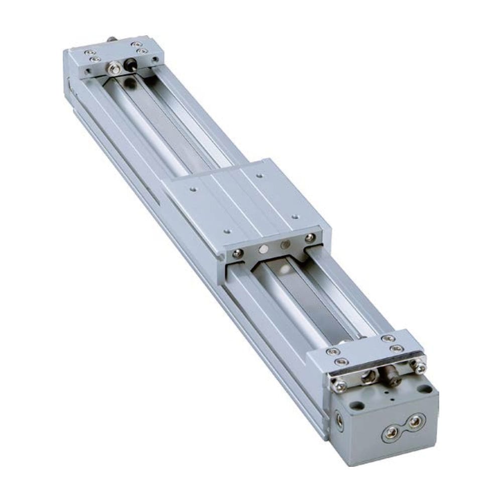
A guided rodless actuator can support a carriage load, but allowable pitch, roll, yaw, speed, and stopping energy remain series-specific.
Rodless cylinders may suit long travel in a short installation envelope, especially where an exposed pushing rod would be vulnerable to buckling. They do not cure opposing load, side load, or overrunning motion by themselves.
Check these limits separately:
- Pneumatic thrust: use measured working pressure.
- Guide moment: calculate each payload force multiplied by its actual offset from the manufacturer’s carriage reference, then apply that series’ combined-load rule.
- Dynamic load: include acceleration, deceleration, vibration, and impact.
- Stroke support: verify every required intermediate support plus profile deflection and machine alignment over the installed span.
- Stopping energy: use moving mass and peak approach speed.
- Control and safety: repeat the full assisting-load, exhaust-back-pressure, startup, stopping, and load-holding analysis used for a rod cylinder.
Parker expresses combined loading through a load-moment factor that sums each applied load or moment divided by its permissible value, with the total limited to 1.0 for the stated conditions. That is a model-specific selection method, not permission to transfer one product’s load rating to another.
See the rodless cylinder load-capacity guide for guide and moment checks, and use the side-loading guide to keep structural guidance separate from pneumatic thrust.
Commission the Two Directions as Separate Operating Cases
SMC’s guide-cylinder software evaluates 7 input groups. Beyond pressure and load weight, it checks mounting orientation, piston speed, moment, kinetic energy, and cushion type. Such breadth makes a static force calculation only the first gate; commissioning must reproduce the real combinations the machine will encounter (SMC Model Selection Software, accessed 2026-07-22).
Record one worksheet row for each direction and load state. Include extension and retraction, maximum and minimum payload, startup, normal travel, end-of-stroke deceleration, commanded stop, and loss of supply where the risk assessment requires it.
Measure or confirm:
- Both cylinder-port pressures throughout the stroke
- Regulator inlet pressure, outlet pressure, and the timing of any dynamic sag relative to cylinder motion
- Stroke time and peak velocity
- Payload mass, center of gravity, attachment offset, guide friction, and any moment transferred into the actuator
- Spring or linkage force at several positions
- Cushion entry speed, adjustment range, final piston speed, and evidence of end-stop impact under the heaviest payload
- Startup, emergency-stop, restart, and loss-of-pressure behavior
Reject a design that passes only at the regulator gauge. Restrictions in a valve, long tube, silencer, or speed controller can make chamber pressure very different from nominal supply. For the stopping-force boundary, use the end-of-stroke force guide.
Document one traceable force basis, one manufacturer selection rule, and measurable acceptance limits. Stacking a friction deduction, safety factor, pressure margin, and oversized bore without identifying the risk behind each allowance is not defensible.
Conclusion: Optimize the Complete Motion, Not the Load Label
ISO 4414 sets the system-level safety scope. SMC and Parker selection methods add direction, load rate, guide moment, and cushioning limits. Read together, these 3 sources support one conclusion: no assisting or opposing label can replace a complete review of force, control stability, stopping, guidance, and machine safety (ISO 4414; SMC; Parker, accessed 2026-07-22).
Assisting force can reduce required actuator output while also creating an overrunning condition and higher stopping energy. Opposing force reduces margin, yet predictable resistance may simplify speed control. Efficiency belongs to the configuration that completes both strokes safely at the required cycle time with the smallest validated actuator and lowest practical regulated pressure.
Sources and Technical References
Engineering decisions in this article rely on 8 primary manufacturer or standards sources. SMC supplies direction, load-rate, speed-control, drop-prevention, and model-selection boundaries; Parker supplies rodless load-moment and cushioning limits; ISO supplies the system-level safety scope. Check product-specific values against the exact current catalog before releasing a machine design.
- AutomationDirect Cylinder Sizing and Force, for bore, area, rod deduction, and differential-pressure relationships; accessed 2026-07-22.
- ISO 4414:2010 Pneumatic Fluid Power Safety Requirements, for the system-level safety, reliability, energy-efficiency, and significant-hazard scope; current edition confirmed 2021.
- Parker Rodless Pneumatic Cylinders Catalog 0900P-7, for OSP-P force, combined-moment, load, speed, and cushioning limits; accessed 2026-07-22.
- SMC Air Cylinder Model Selection, accessed 2026-07-22.
- SMC ASS Safety Speed Control Valve, for the transition between initial meter-in pressurization and normal meter-out control; accessed 2026-07-22.
- SMC Control Air Flow of Cylinders, accessed 2026-07-22.
- SMC Drop Prevention, accessed 2026-07-22.
- SMC Guide Cylinder Selection Software, for its orientation, pressure, speed, load, moment, kinetic-energy, and cushioning input set; accessed 2026-07-22.
FAQs About Assisting and Opposing Pneumatic Loads
SMC’s model-selection guide separates extension from retraction, while its flow-control guidance explains that exhaust back pressure changes piston speed. These 5 answers preserve that distinction: load direction determines the force sign, but pressure, control stability, guidance, cushioning, and holding risk still require separate checks (SMC, accessed 2026-07-22).
How do I determine whether a pneumatic load is assisting or opposing?
Choose the commanded travel direction, then compare every external force with it. Same-direction forces assist; opposite forces resist. Repeat this classification for the return stroke and at every position where a spring, cam, lever, or linkage changes force direction.
Does an assisting load always reduce air consumption?
No. It reduces required actuator force only when the external force helps the commanded motion. Air use falls only if the design can safely use lower regulated pressure, a smaller cylinder, fewer charged volumes, or another measurable change. Unchanged pressure and cylinder volume do not create an automatic saving.
Why can a gravity-assisted cylinder move unpredictably?
Gravity can create an overrunning load. Meter-out control often adds stabilizing exhaust back pressure, which must also be subtracted from net cylinder force when checking the weakest stroke. Test the full payload range. Never treat a speed controller as a load-holding device.
Should I use a fixed pressure percentage for opposing loads?
No. Calculate the actual opposing force and use the lowest credible pressure difference across the cylinder during motion. Apply one documented selection factor. Fixed pressure additions can duplicate other margins, hide a restricted air path, or push the proposed operating pressure beyond component and plant limits.
Do rodless cylinders handle assisting and opposing loads better than rod cylinders?
Not categorically. Rodless designs avoid exposed piston-rod buckling and can save installation length, but their carriage, guide moments, profile support, cushion energy, and control circuit still limit the application. Compare exact catalog limits and the complete load path for each design.