

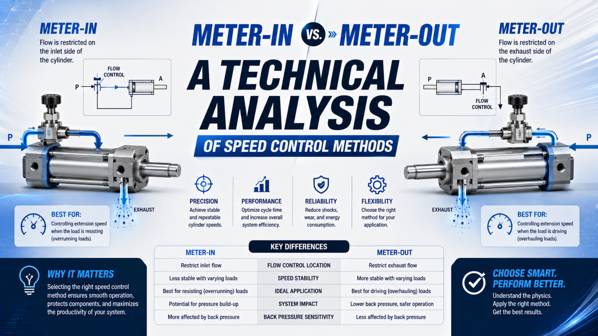
Meter-in restricts air entering the driving chamber; meter-out restricts air leaving the opposite chamber. For most double-acting cylinder retrofits, the engineering question isn’t whether meter-out sounds better. It is whether the rebuilt circuit actually meters exhaust, retains enough force, controls the first stroke after repressurization, and stays stable across the permitted load range.
This article is a conversion-validation procedure. Use the companion meter-in versus meter-out selection guide when choosing the control method for a new circuit. Use the tests below when an installed machine has been replumbed, a speed controller has been replaced, or maintenance may have reversed the metering direction.
Key Takeaways
- Parker directs the full-flow arrow toward the cylinder for meter-out control.
- Record both cylinder-port pressures, not only the regulator gauge.
- Test the first stroke after complete depressurization separately.
- Inject minimum pressure, payload limits, and exhaust restriction before acceptance.
- A speed controller is not a load-holding safety device.
What Does a Meter-In-to-Meter-Out Retrofit Actually Change?
Parker states that its one-way flow control passes minimum-restriction flow in the arrow direction and meters the opposite direction; for meter-out, the full-flow arrow points toward the cylinder port (Parker Flow Control Valve Instructions, accessed July 22, 2026). The retrofit changes which air path the needle controls.
During one cylinder stroke, the directional valve connects supply to the driving chamber and connects the opposite chamber to exhaust. Meter-in control is the arrangement that puts the adjustable restriction in the driving chamber’s supply path. Meter-out control is the arrangement that meters the opposite chamber’s exhaust while allowing relatively free inlet flow.
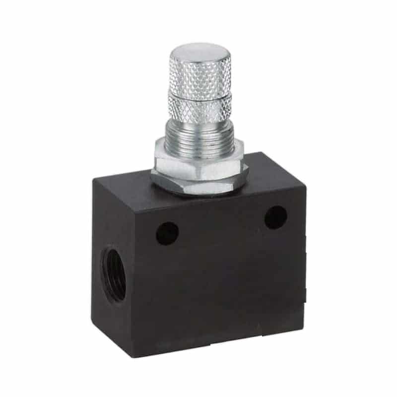
The word “relatively” matters. Meter-out doesn’t guarantee full regulator pressure at the driving port. The directional valve, tubing, fittings, manifold, and shared supply can still create a dynamic pressure loss. Likewise, the exhausting chamber doesn’t sit at one fixed back pressure. Its pressure changes with needle position, piston speed, load, cylinder volume, and downstream restrictions.
| Circuit state | Free-flow direction | Metered direction | Expected control effect |
|---|---|---|---|
| Meter-in | From cylinder toward valve | From valve toward cylinder | Restricts chamber filling |
| Meter-out | From valve toward cylinder | From cylinder toward valve | Restricts chamber exhaust |
The useful retrofit test is directional, not visual. An elbow speed controller can be rotated without changing its internal check-valve direction. Verify the printed symbol or arrow and trace the connected ports. A body that appears to “point at” the cylinder may still be configured for the wrong metering direction.
Baseline Data Before Conversion
SMC notes that cylinder speed depends on airflow only when inlet pressure is held constant and that port and tubing sizes also affect motion (SMC Control Air Flow of Cylinders, accessed July 22, 2026). A useful baseline therefore needs pressure, time, load, and circuit data from the same cycle.
Record at least ten consecutive cycles with the existing configuration. Don’t tune the needle between runs. Capture cold-start behavior first, then normal-temperature behavior after the machine reaches its usual production state.
Use one row for extension and another for retraction:
| Baseline field | What to record | Why it matters after conversion |
|---|---|---|
| Stroke definition | PLC command-to-sensor and motion-only time | Separates valve delay from travel time |
| Valve inlet pressure | Minimum pressure during motion | Reveals shared-supply collapse |
| Cap-end pressure | Trace through the full stroke | Identifies driving or exhausting behavior |
| Rod-end pressure | Trace through the full stroke | Shows whether back pressure is controlled |
| Payload | Minimum, nominal, and maximum approved mass | Exposes load-sensitive acceleration |
| Orientation | Horizontal, vertical up, vertical down, or linkage angle | Identifies assisting-load conditions |
| Controller setting | Part number, control type, turns, and lock position | Makes the test repeatable |
| Exhaust hardware | Directional-valve port, silencer, and quick exhaust | Identifies bypasses and secondary restrictions |
| Impact behavior | End-stop noise, rebound, cushion entry | Prevents speed tuning from hiding an energy problem |
| First stroke | Result after full depressurization and refill | Detects missing initial exhaust restraint |
If the existing circuit is already unsafe or produces uncontrolled motion, don’t run a broad baseline. Secure the load, isolate the hazard, and use the machine’s approved diagnostic procedure. Baseline data are useful only when they can be collected without exposing people or equipment.
For an initial speed estimate before testing, use the Cylinder Speed Calculator. Treat the result as a pre-check, since a calculated average speed cannot predict stiction, startup pressure buildup, or a load that assists motion.
How Do You Verify the Controller Direction Before Repressurizing?
Parker recommends two one-way flow controls for most double-acting cylinders and says they should be installed as close to the cylinder ports as piping permits (Parker Flow Control Valve Instructions, accessed July 22, 2026). Verify both paths while the machine is isolated and depressurized.
Use the exact schematic and component datasheet. Don’t infer direction from knob color, elbow orientation, or the part that was removed. SMC, for example, sells visually similar meter-out and meter-in speed-controller variants with different model codes (SMC 10-AS-F Speed Controller Catalogue, accessed July 22, 2026).
Follow this pre-pressure check:
- Isolate electrical and pneumatic energy according to the machine procedure.
- Mechanically support any load that could move under gravity or stored force.
- Identify the directional valve’s supply, work, and exhaust ports from its symbol.
- Trace each work line to its cylinder port without assuming the tube colors are correct.
- Confirm that free flow points toward each cylinder port for meter-out operation.
- Confirm that exhaust from each cylinder port passes through the adjustable restriction.
- Check that a quick-exhaust valve or alternate branch does not bypass the intended control.
- Record the exact controller part number and its specified flow direction.
The same physical valve isn’t automatically reusable after a conversion. Some one-way controls can be reversed or replumbed; others are sold as dedicated meter-in or meter-out versions. Use the model-specific symbol. If its identity or direction cannot be verified, replace it with a documented component before testing.
How Do Two Port-Pressure Traces Prove the Retrofit?
SMC describes exhaust-port control as the most common industry method and links the changing exhaust back pressure to piston speed (SMC Control Air Flow of Cylinders, accessed July 22, 2026). Two cylinder-port traces show whether the intended driving and resisting pressures actually exist during motion.
Install suitable pressure transducers close to both cylinder ports. Record valve inlet pressure as a third channel when possible. Time-align the pressure data with the directional-valve command, first detected motion, end sensor, and load state.
For a meter-out extension, the expected pattern is qualitative:
- Cap-end pressure rises to provide driving force.
- Rod-end pressure remains above the downstream exhaust pressure while the piston moves.
- Changing the rod-end controller alters stroke speed and rod-end pressure.
- The controller has a useful adjustment range rather than acting only in the last fraction of a turn.
For retraction, the roles reverse. Rod-end pressure drives the piston while cap-end exhaust is metered. The two needle positions don’t need to match because piston areas, loads, cushions, and target times can differ.
| Trace result | Likely interpretation | Next check |
|---|---|---|
| Valve inlet collapses during both strokes | Upstream restriction or shared demand | Regulator, manifold, branch tubing, concurrent actuators |
| Driving port stays low while inlet remains stable | Supply-path restriction | Directional valve, fitting, tube ID, reversed controller |
| Exhaust pressure stays near downstream pressure | No effective meter-out restraint | Check-valve direction, bypass, needle position |
| Exhaust pressure rises until motion stalls | Excess restriction or inadequate force margin | Load, bore, supply pressure, silencer, needle setting |
| Needle movement barely changes the trace | Another component dominates | Muffler, cushion, valve path, tube, quick exhaust |
| Pressure changes but end impact remains | Cushioning or stopping-energy problem | Cushion setting or external shock absorber |
Synchronizing the PLC command with both pressure traces separates three delays that a stopwatch combines: valve switching, pressure buildup before breakaway, and piston travel. A conversion can improve travel stability while leaving a supply or switching delay untouched. Record those intervals separately before declaring the retrofit successful.
Use the back-pressure guide when the resisting-port pressure consumes too much force. For supply-side variations, compare the traces with the pressure-fluctuation troubleshooting guide.
Which Fault-Injection Tests Should the Retrofit Pass?
ISO 4414:2010 addresses significant pneumatic-system hazards across design, installation, adjustment, operation, and maintenance, and ISO confirmed the standard in 2021 (ISO 4414, accessed July 22, 2026). Fault injection should stay inside the machine’s risk assessment, approved load envelope, and documented test procedure.
These tests are controlled boundary checks, not permission to create a hazardous failure. Use suitable guarding, independent load support, qualified personnel, and defined abort limits.
Fault injection is a planned test that introduces one approved boundary condition while every other relevant variable is controlled and recorded. It is not an improvised blockage, overload, or unsafe loss of support.
Test 1: Minimum dynamic supply pressure
Run the accepted motion at the lowest permitted valve-inlet pressure while other approved consumers follow the worst overlapping sequence. Confirm stroke completion, pressure margin, and sensor timing. If the machine passes only at an unusually high regulator setting, the retrofit may be hiding a supply restriction.
Test 2: Minimum and maximum payload
Test both ends of the approved payload range. A heavy resisting load can expose inadequate driving force; a light assisting load can expose overrunning behavior. Use the actual load direction for each stroke. “Light” and “heavy” are less important than whether the external force resists or assists movement.
Test 3: Controlled exhaust restriction
Use only a risk-assessed restriction fixture specified in the test plan. Before testing, record normal exhaust backpressure and define the target fault backpressure, maximum permitted pressure, hold time, and immediate abort threshold for the exact valve, tubing, silencer, and load combination. Increase restriction only within those approved limits and confirm that the expected diagnostic or maintenance response occurs. Never improvise a blockage or treat a serviceable replacement silencer as the fault condition; the purpose is to verify a defined response without creating uncontrolled pressure.
Test 4: Full depressurization and restart
Exhaust the relevant zone through its designed isolation system, confirm the safe state, then restore pressure using the approved sequence. Record the first commanded movement separately from later cycles. Repeat only after the system has returned to the defined initial condition.
In our experience, tests at nominal pressure and nominal payload rarely expose an incorrect conversion. The useful failures appear at transitions: the first refill, a light descending load, a shared-air pressure dip, or a silencer that adds unexpected resistance. Define those transitions before tuning so the needle isn’t adjusted around one convenient operating point.
Do not treat a pilot-operated check valve as a universal remedy for vertical-load risk. Leakage, trapped-air compressibility, pilot-pressure loss, hose failure, and restart behavior still need evaluation. The pilot-operated check valve guide explains the pneumatic function; the machine risk assessment determines whether additional mechanical holding is required.
Why Must the First Stroke After Repressurization Be Tested Separately?
Parker’s P33 soft-start instructions switch to full flow at approximately 50% of inlet pressure and warn that inline meter-out controls may not regulate adequately while a depressurized system is refilling (Parker P33 Instructions, accessed July 22, 2026). The first actuation can therefore differ from steady cycling.
Meter-out needs air in the exhausting chamber to develop useful resisting pressure. After full depressurization, that chamber may be empty or only partly refilled. If the directional valve commands motion before the circuit reaches its intended initial state, the needle can have much less authority over the first movement.
Record these restart variables:
- pressure-restoration command and actual valve-inlet pressure rise;
- cap-end and rod-end pressure before the motion command;
- directional-valve state during refill;
- time from pressure restoration to motion enable;
- first-stroke time and peak speed;
- end impact, rebound, and sensor sequence;
- results of the second and later strokes for comparison.
A soft-start device can reduce pressurization shock, but it doesn’t automatically establish a safe restart sequence. The selected component, fill volume, valve state, trapped-air paths, and machine logic must work together. Parker also notes that check valves and closed-center valves can trap pneumatic energy downstream of an exhaust valve, so isolation boundaries need explicit verification.
If the first stroke remains abnormal, stop tuning the steady-cycle needle. Review refill state, valve position, pressure restoration, cylinder loading, and control logic first. The meter-out circuit troubleshooting guide covers startup and ordinary motion faults in more detail.
Acceptance Evidence for the Final Record
Parker specifies two flow controls for most double-acting cylinders so extension and retraction can be adjusted independently (Parker Flow Control Valve Instructions, accessed July 22, 2026). Acceptance should likewise document each stroke, each load direction, and each controller separately under defined conditions.
Use predetermined limits instead of statements such as “runs smoothly.” The final record should include:
| Acceptance item | Evidence | Pass limit source |
|---|---|---|
| Controller identity | Part number, symbol, and flow direction | Manufacturer datasheet |
| Installation | Port map, tube route, and locked needle setting | Approved schematic |
| Stroke time | Command-to-sensor and motion-only results | Machine specification |
| Dynamic pressure | Valve inlet and both cylinder-port traces | Engineering calculation and test plan |
| Load coverage | Minimum, nominal, and maximum payload | Approved operating envelope |
| Supply boundary | Result at minimum dynamic inlet pressure | Pneumatic design requirement |
| Restart | First stroke after full depressurization | Risk assessment and startup specification |
| Exhaust path | Directional valve, silencer, and bypass state | Component documentation |
| End-of-stroke behavior | Cushion entry, impact, and rebound | Cylinder and shock-absorber limits |
| Safety boundary | Holding and safe-state test evidence | Machine safety validation |
Compare at least ten stable cycles at each required operating condition when the acceptance plan needs repeatability data. Report the individual results or range, not an invented improvement percentage. If a sensor defines completion, state its switching position and filtering because sensor timing can change without a corresponding change in piston speed.
Needle turns alone are not transferable between valve sizes or manufacturers. Record the physical part, pressure conditions, payload, and measured motion with the setting. After maintenance, the same record lets a technician determine whether performance changed because of adjustment, contamination, supply pressure, or another component.
For end impacts that remain after the mid-stroke speed is stable, tune the cylinder cushion separately and check the pneumatic cushioning guide. A nearly closed cushion should not substitute for whole-stroke speed control.
Where Does Meter-Out Control Stop Being the Right Solution?
SMC’s ASD family combines meter-in and meter-out adjustment in one controller, demonstrating that the two methods are not mutually exclusive in every circuit (SMC ASD Dual Speed Controller, accessed July 22, 2026). Some startup, low-speed, and single-acting applications need a different or combined strategy.
Meter-out is a strong default for a double-acting cylinder with a variable or assisting load. It is not a universal answer. Reconsider the architecture when:
- the required speed is below the cylinder’s stable low-speed range;
- seal or guide friction produces stick-slip despite correct metering;
- the process needs commanded intermediate positions rather than endpoint timing;
- exhaust back pressure removes too much force margin;
- a quick-exhaust function must bypass the normal exhaust route;
- startup needs staged meter-in and normal travel needs meter-out;
- the axis needs safety-rated holding or controlled stopping after energy loss.
Proportional flow control, a low-friction cylinder, pressure regulation by direction, a mechanical brake, a rod lock, a shock absorber, or an electric actuator may address a problem that a manual needle cannot. Select the function from the measured failure mode.
Meter-out also shouldn’t be credited with automatic energy savings. Back pressure consumes net force, while the total air use depends on chamber volumes, operating pressures, cycle rate, leaks, and the wider circuit. Compare energy only after the motion and force requirements are met.
Meter-In vs. Meter-Out Retrofit FAQs
Parker’s installation instructions define two arrow orientations, toward the cylinder for meter-out and away from it for meter-in, while its P33 instructions identify the first refill as a separate operating condition (Parker Flow Control Instructions; Parker P33 Instructions, accessed July 22, 2026). These answers focus on conversion verification.
Can the same speed controller be reused when converting to meter-out?
Only when its manufacturer permits the required orientation and its part number, symbol, pressure range, and flow capacity are verified. Some controllers can be replumbed; others are dedicated meter-in or meter-out versions. Confirm that free flow points toward the cylinder and exhaust passes through the adjustable restriction before applying pressure.
What pressure should a meter-out exhaust chamber maintain?
There is no universal 1 or 2 bar target. Required back pressure depends on load direction, friction, piston area, supply pressure, speed, valve capacity, and force margin. Measure both cylinder ports during motion. Use enough exhaust restraint for stable control while retaining sufficient net force across the approved operating envelope.
Does meter-out make a vertical cylinder safe after air loss?
No. Meter-out regulates normal exhaust flow; it is not a safety-rated holding function. Leakage, hose failure, valve state, trapped-air behavior, and gravity can still produce movement. The machine risk assessment may require a mechanical brake, rod lock, counterbalance arrangement, monitored pneumatic device, or another validated protective measure.
Why is only the first stroke too fast after pressure restoration?
The exhausting chamber may not yet contain enough air for the restriction to generate normal back pressure. Check the soft-start device, directional-valve state, refill volume, motion-enable delay, and both cylinder-port pressures before changing the normal-cycle needle setting. Validate the first stroke from a repeatable fully depressurized state.
Can a quick-exhaust valve be used with meter-out control?
Yes, but only with a circuit-specific review. A quick-exhaust valve can bypass the directional valve and may also bypass the intended metering path. Define which stroke should exhaust rapidly, which stroke needs restraint, and how restart behaves. Verify the actual plumbing and pressure traces rather than assuming the two functions remain independent.
Sources and technical references
- Parker Flow Control Valve Instructions, flow direction, meter-in/meter-out orientation, placement, adjustment, and depressurization requirements.
- SMC Control Air Flow of Cylinders, exhaust-side flow control, constant-inlet-pressure condition, and other speed variables.
- SMC 10-AS-F Speed Controller Catalogue, separate meter-out and meter-in model designations and flow curves.
- Parker P33 Safety Exhaust Valve Instructions, soft-start threshold, first-actuation warning, isolation limits, and commissioning requirements.
- ISO 4414:2010, pneumatic-system safety requirements for design, installation, adjustment, operation, and maintenance.
- SMC ASD Dual Speed Controller, combined meter-in and meter-out control capability.