

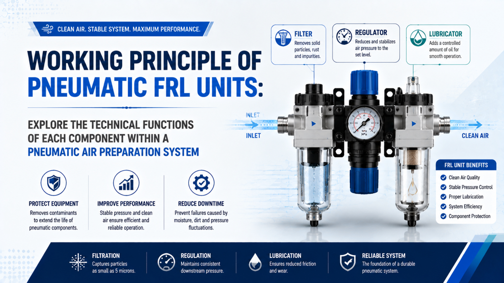
A pneumatic FRL unit is a point-of-use air-preparation assembly that conditions compressed air in sequential stages. The filter captures specified solid particles and separates bulk liquid droplets. The regulator reduces inlet pressure and controls the downstream setpoint within its flow range. The lubricator, when the equipment actually requires one, meters oil into a moving airstream.
Those functions are related, but they aren’t interchangeable. A bowl filter doesn’t remove water vapor like a dryer. A regulator doesn’t create missing flow. A lubricator doesn’t automatically improve every modern cylinder or valve. Understanding those limits is the fastest way to diagnose an FRL without replacing the wrong component.
Key Takeaways
- ISO 8573-1 classifies particles, water, and oil separately.
- Festo lists 5 and 40 micrometers as model-specific filter grades, not universal FRL requirements.
- CAGI gives 5-7 psig differential pressure as a general filter-element service trigger.
- Lubrication belongs only where every downstream component and process permits it.
This guide concentrates on the internal flow path and dynamic behavior. For broader sizing, maintenance, application, and RFQ decisions, use the air source treatment unit selection guide. For fault isolation, see the FRL reliability troubleshooting guide.
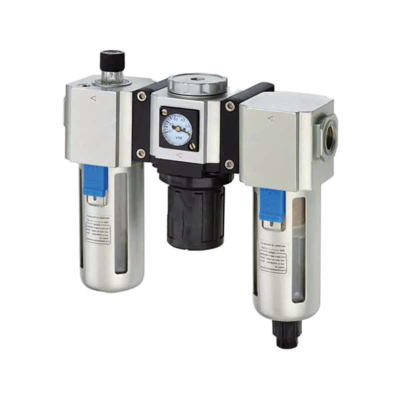
A three-element FRL places the filter first, pressure regulator second, and lubricator last when oil mist is permitted.
What Happens to Air as It Passes Through an FRL Unit?
Festo’s 2026 MSB6N combination data lists 5 or 40 micrometer filtration and a 1 to 12 bar regulation range for specific configurations. Those values show why FRL function must be read from the selected assembly, not inferred from its three bowls or port size (Festo MSB6N, 2026).
Air should enter the port marked as the inlet and follow the manufacturer’s flow arrow. In a conventional three-part assembly, the stages operate in this order:
- Filter: changes contaminant loading by separating bulk liquid and retaining particles above the element’s rated performance.
- Regulator: changes pressure by throttling the inlet passage in response to downstream pressure and adjusting-spring force.
- Lubricator: changes oil content by drawing metered lubricant into a sufficiently fast airstream.
The sequence matters. Filtering before regulation protects the regulator’s small seat and moving parts. Regulation before lubrication keeps oil from coating the regulator diaphragm and allows the lubricator to operate at the intended downstream pressure. The lubricator sits last so added oil isn’t immediately removed by an upstream filter stage.
An FRL is also more than those three letters. A practical air-preparation station may include a lockable shut-off valve, soft-start or dump valve, pressure sensor, pressure gauge, dryer, fine filter, branching module, or flow sensor. Festo’s modular service-unit catalog illustrates this broader architecture. The assembly should match the machine function rather than a fixed three-piece tradition (Festo air preparation units, accessed 2026).
The most useful way to read an FRL schematic is to assign one controlled variable to each stage. The filter controls specified contamination, the regulator controls pressure, and the optional lubricator controls oil delivery. When a symptom belongs to another variable, such as pressure dew point, peak flow, stored energy, or exhaust restriction, adding another standard FRL bowl won’t solve it.
How Does the Filter Separate Liquid and Capture Particles?
ISO 5782-1:2017 covers compressed-air filters rated up to 1,600 kPa and 80°C that remove solid and liquid contaminants by mechanical means. It does not say one nominal micron grade controls every contaminant form or every application (ISO 5782-1, 2017).
Incoming air is directed around a deflector or vane so it rotates inside the bowl. Larger droplets and heavier particles resist the change in direction more than the surrounding air. They move toward the bowl wall, lose momentum, and collect below the flow path. This inertial separation stage reduces the liquid and particle load reaching the element.
Air then passes through the filter medium. The element retains particles according to its design, grade, and test method. Festo describes 40 and 5 micrometer sintered-filter stages in its general operating guidance, then identifies separate fine and microfilter stages for tighter requirements (Festo general operating conditions, 2025).
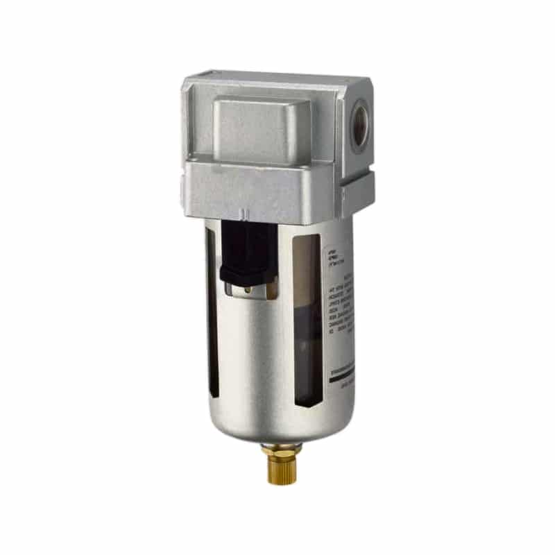
A bowl filter combines inertial liquid separation, an internal element, and a drain that must remain functional.
Three limits deserve attention:
- Water vapor passes through. A dryer controls pressure dew point. The filter only separates water that has condensed into liquid droplets.
- Oil aerosol needs the right filter stage. A general particulate element isn’t automatically a coalescing element. Use the coalescing-filter guide when oil aerosol is part of the target.
- Collected condensate must leave the bowl. Manual, semi-automatic, and automatic drains can all fail or be misapplied. Liquid reaching the element or outlet can be carried downstream.
What should the filter accomplish? Start with the purity requirement at a named measurement point. ISO 8573-1:2010 treats particles, water, and oil as separate classifications. A “5 micrometer filter” is therefore a component specification, not a complete compressed-air purity class.
The Regulator: Spring Force, Diaphragm Feedback, and Outlet Pressure
ISO 6953-1:2024 applies to several direct-acting and pilot-operated regulator types, with rated inlet pressure up to 25 bar and adjustment pressure up to 16 bar. The range is a standards scope, not a rating for every FRL regulator (ISO 6953-1, 2024).
A common direct-acting regulator contains an adjusting spring, diaphragm, valve stem, poppet, valve seat, and sometimes a relieving passage. Turning the knob changes spring compression. The spring pushes the diaphragm and opens the inlet poppet. Air enters the downstream chamber until outlet pressure acting on the diaphragm creates enough opposing force to move the poppet toward its seat.
Regulator droop is the reduction in controlled outlet pressure as flow demand rises from the no-flow setpoint. It results from the pressure difference required to move air through the valve seat and other restrictions.
A simplified static relationship is:
Here, is adjusting-spring force, is downstream gauge pressure, is effective diaphragm area, and groups friction and other internal closing forces. This relationship explains the feedback direction, but it doesn’t replace the manufacturer’s pressure-flow curve, relieving characteristic, hysteresis, or accuracy data.
When downstream demand increases, pressure falls slightly and spring force moves the poppet farther open. When demand stops, pressure recovers and the poppet closes. An inlet-pressure-compensated design reduces the effect of supply variation, but no passive regulator can create pressure above its inlet or deliver unlimited flow through a fixed seat.
A relieving regulator can vent some excess secondary pressure through its relief path when the setpoint is lowered or downstream pressure rises. A non-relieving regulator doesn’t provide that internal exhaust path. Neither description proves that a regulator is a machine safety dump valve. Check flow direction, return-flow behavior, relieving capacity, and residual-pressure requirements separately.
Why Does Regulated Pressure Fall During High Flow?
CAGI states that well-designed compressed-air systems usually limit total pressure drop from compressor discharge to a point of use to 10%. An FRL consumes part of that budget through its filter, regulator seat, lubricator, fittings, and local piping (CAGI Pressure Drop Technical Brief, 2026).
The regulator gauge may show the setpoint when the machine is idle, then fall when several cylinders move. That isn’t automatically a failed regulator. Flow through each restriction requires a pressure difference. As demand rises, the filter and internal passages consume more pressure, while the regulator poppet must open farther to supply the outlet.
The flowing FRL loss is:
Here, is pressure lost across the assembled FRL during the selected event. The inlet and outlet readings must be synchronized under flow. Static readings cannot reveal the same restriction.
Treat FRL diagnosis as a three-point measurement. Record pressure immediately before the FRL, immediately after it, and at the valve or actuator inlet. If the first point holds while the second falls, focus on the FRL. If both fall together, move upstream. If the FRL outlet holds but the actuator inlet falls, inspect downstream tube, fittings, valve, and manifold.
| Dynamic observation | Most useful next check |
|---|---|
| FRL inlet and outlet fall together | Header, branch pipe, receiver, compressor control, simultaneous demand |
| Inlet holds while outlet falls | Filter differential, regulator curve, lubricator restriction, undersizing |
| FRL outlet holds while actuator pressure falls | Hose, coupling, manifold, valve, fitting, local tube ID |
| Pressure holds but cylinder remains slow | Exhaust restriction, flow control, load, friction, alignment |
When the supplier publishes , use it with the actual inlet pressure, outlet pressure, and required flow. When the catalog uses ISO 6358 conductance, nominal flow, or a pressure-flow graph, stay with that method. Don’t compare a flow value directly with .
For complete peak-flow calculations, catalog-curve interpretation, and a worked clamp-station example, use the FRL sizing guide. For losses outside the FRL, follow the compressed-air pressure-drop troubleshooting workflow.
How Does a Pneumatic Lubricator Generate Oil Mist?
Festo states that an air-line lubricator functions only when airflow is sufficiently strong. SMC therefore publishes model-specific minimum-flow information rather than one universal pickup value. Low or intermittent flow can leave the sight dome apparently adjusted while little oil reaches the downstream device (Festo general operating conditions, SMC air-combination guide, accessed 2026).
Air passing through the lubricator’s restricted throat develops a local pressure difference. Reservoir pressure and the metering arrangement move oil up the pickup tube. The oil enters the high-velocity air region, breaks into droplets, and is carried downstream. A sight dome lets the technician observe the metered feed, but drop count alone doesn’t prove delivery at the final component.
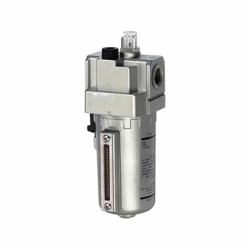
An air-line lubricator meters oil into the downstream air only when pressure, flow, oil level, and adjustment meet its operating conditions.
Oil transport changes with flow, pipe length, elevation, fittings, branch layout, and duty cycle. Long horizontal runs and low-flow branches may collect oil instead of carrying a stable mist. Exhausted oil can also reach silencers, sensors, products, and the surrounding workspace.
Check five conditions before trusting a lubricator:
- The oil type matches the lubricator and every downstream component.
- Operating pressure and temperature remain inside the product rating.
- Minimum airflow is achieved during the intended cycle.
- The lubricator is close enough to serve its assigned equipment according to the manufacturer.
- The reservoir, pickup tube, metering needle, and sight dome remain clean and functional.
Does Every Pneumatic System Need the “L” Stage?
Festo lists at least eight service-unit function families, including filters, regulators, dryers, sensors, valves, and lubricators. That modular range confirms that modern air preparation isn’t automatically a three-bowl FRL. Many stations correctly use only a filter and regulator (Festo compressed-air service units, accessed 2026).
Add a lubricator only when the downstream equipment manual requires or permits continuous oil-mist lubrication. Many contemporary cylinders and valves leave the factory with grease intended for long-term operation. Adding incompatible oil can wash out that grease, swell seals, contaminate the process, or make future oil-free operation impractical.
Once line lubrication has been introduced, don’t stop it casually. Festo’s MSB6N documentation notes that when operation with oil lubrication is used, lubrication may be required for continued service. Confirm the exact downstream product instructions before changing the policy (Festo MSB6N, 2026).
Lubrication is a branch-wide compatibility decision, not a lubricator-only decision. One oil-mist unit can affect every valve, seal, sensor, exhaust silencer, and process surface downstream. The approval record should therefore name the oil, affected devices, exhaust destination, refill method, and consequence of an empty reservoir.
| Downstream condition | Normal decision path |
|---|---|
| Component manual requires line oil | Select compatible oil and verify minimum flow |
| Factory-lubricated cylinder and valves | Do not add oil unless all manuals permit it |
| Paint, electronics, clean process, or sensitive product | Prefer an oil-free branch and control upstream oil |
| Air tool designed for continuous oil mist | Use a correctly sized lubricator near the tool |
| Mixed branch with incompatible requirements | Split the branch before adding lubrication |
For rodless cylinders, cycle rate alone doesn’t decide the answer. Follow the cylinder’s approved medium and lubrication instructions. A high-cycle actuator that is designed for non-lubricated air can be harmed rather than helped by an arbitrary oil feed.
What Can an FRL Remove, and What Requires Other Treatment?
ISO 8573-1:2010 defines three primary compressed-air purity classifications for particles, water, and oil. A standard FRL filter addresses only part of those categories, so a clear bowl or nominal micron rating cannot prove that the complete air-quality target has been met (ISO 8573-1, 2010).
| Air-quality requirement | Standard FRL contribution | Additional treatment or evidence |
|---|---|---|
| Larger solid particles and pipe scale | Particulate element | Finer staged filtration and particle measurement when required |
| Bulk liquid water | Inertial separation and drain | Dryer for water vapor and pressure-dew-point control |
| Oil aerosol | Only when a suitable coalescing stage is included | Coalescing element selected for required residual oil |
| Oil vapor | Standard element is not sufficient | Adsorption or process-specific treatment |
| Stable machine pressure | Regulator within its operating envelope | Adequate upstream capacity and correctly sized piping |
| Controlled stored energy | Optional shut-off and dump functions | Machine safety design, isolation, verification, and restraint |
A dryer belongs upstream when the coldest downstream temperature can condense remaining vapor. The pressure-dew-point guide explains why relative humidity at room conditions isn’t enough to specify compressed-air drying.
Pressure dew point is the temperature at which water vapor begins to condense at the stated compressed-air pressure. It is a dryer and system requirement, not a bowl-filter micron rating.
Fine filtration should also be staged. Installing a very fine element directly into a dirty line can load it quickly and create excess pressure drop. Follow the filter manufacturer’s prefiltration requirements, rated flow, initial differential, terminal differential, and drain arrangement.
ISO purity classes apply at a stated measurement point. If the class is required at a valve island, test or specify it there. A compressor-room certificate doesn’t account for downstream corrosion, wet branches, incompatible lubricant, or contamination introduced after the measurement point.
FRL Installation and Commissioning Checks
CAGI recommends replacing filter elements at 5-7 psig differential pressure or at least every six months as a general rule. The selected manufacturer’s limit and the site’s contamination target remain controlling, so commissioning should establish a clean baseline before that trigger is used (CAGI Pressure Drop Technical Brief, 2026).
Install the FRL where its flow arrow, bowl orientation, drain access, gauge, adjustment lock, and service clearances match the documentation. Protect polymer bowls from incompatible chemicals and impact. Use a metal bowl or guard when the environment requires it. Support the assembly so pipe strain doesn’t load the modular connectors.
Before pressurizing:
- verify the inlet and outlet ports;
- confirm filter grade, pressure range, bowl material, and drain type;
- check that every downstream device permits the selected lubricant policy;
- set the regulator knob to a low initial setting;
- close drains and fill the lubricator only with approved oil;
- confirm that guards and mounting brackets are secure.
Pressurize gradually. A soft-start function may be required to prevent unexpected actuator motion. Set pressure while approaching the target in the direction specified by the regulator manufacturer, then lock the knob. Reproduce the highest-flow production event and record inlet pressure, outlet pressure, actuator pressure, and cycle time.
For maintenance covered by US requirements, OSHA 29 CFR 1910.147 includes pneumatic energy and requires potentially hazardous stored or residual energy to be relieved, disconnected, restrained, or otherwise made safe. Closing an inlet valve or reading zero upstream doesn’t prove that every downstream volume is depressurized (OSHA 1910.147).
Use this commissioning record:
| Check | Record |
|---|---|
| Identity | Manufacturer, model, module order, filter grade, drain, bowl, port |
| Static pressure | Inlet and outlet before demand |
| Dynamic pressure | Inlet, FRL outlet, and critical point during peak flow |
| Filter baseline | Clean-element differential pressure |
| Regulator behavior | Setpoint, droop, creep, relieving or non-relieving response |
| Drain | Manual or automatic operating test |
| Lubricator | Oil type, initial setting, minimum-flow confirmation |
| Isolation | Shut-off, residual-pressure release, gauge location, verification method |
| Acceptance | Maximum pressure loss, air-quality target, cycle time, service triggers |
The detailed adjustment and condition-based service sequence belongs in the FRL setup and maintenance guide. This functional check establishes whether each stage is operating as the schematic claims.
Pneumatic FRL Working Principle FAQs
CAGI’s 5-7 psig differential-pressure trigger is useful only after the filter’s clean baseline and manufacturer limit are known. The same principle applies throughout an FRL: identify the controlled variable, measure it during real flow, and compare it with product-specific data rather than a generic port-size rule (CAGI, 2026).
Does every pneumatic FRL unit need a lubricator?
No. Many modern cylinders and valves use factory-applied grease and are intended for non-lubricated compressed air. Add an oil-mist lubricator only when all downstream manuals and the process permit it. Once oil has been introduced, continued lubrication may be required, so document the policy before changing it.
Can an FRL filter remove water vapor?
No. A standard bowl filter can separate liquid droplets and retain particles according to its element rating, but water vapor passes through. A dryer controls pressure dew point. Specify the required ISO 8573-1 water class at a named measurement point, then select and verify the drying system.
Why does the regulator gauge fall during cylinder motion?
Flow through the filter, regulator seat, lubricator, fittings, and pipe requires a pressure difference. A static gauge may show the setpoint while dynamic pressure drops during peak demand. Measure before and after the FRL during the same event, then compare the result with the exact regulator flow curve.
What order should the filter, regulator, and lubricator follow?
The conventional sequence is filter, regulator, then lubricator. Filtering protects the regulator, pressure regulation establishes the lubricator’s supply condition, and lubrication comes last so added oil travels downstream. Follow the actual product flow arrows and assembly instructions because combination modules can place functions inside one housing.
How do you know when an FRL needs service?
Use measured triggers: filter differential pressure, bowl liquid level, drain function, regulator droop or creep, lubricator oil level, and physical condition. CAGI gives 5-7 psig as a general filter differential trigger, but the product limit and air-quality requirement may demand earlier service.
Sources and technical references
- ISO 8573-1:2010: compressed-air contaminant and purity classifications for particles, water, and oil. Retrieved 2026-07-27.
- ISO 5782-1:2017: supplier-literature and marking characteristics for compressed-air filters. Retrieved 2026-07-27.
- ISO 6953-1:2024: supplier-literature and marking characteristics for pressure regulators and filter-regulators. Retrieved 2026-07-27.
- ISO 4414:2010: general rules and safety requirements for pneumatic systems and components. Retrieved 2026-07-27.
- Festo general operating conditions: filter, regulator, lubricator, flow, and air-preparation guidance. Retrieved 2026-07-27.
- Festo MSB6N air-preparation combination: model-specific filtration, regulation, flow-curve, lubrication, and operating data. Retrieved 2026-07-27.
- SMC FRL handling precautions: regulator, filter-regulator, lubricator, residual-pressure, and handling warnings. Retrieved 2026-07-27.
- CAGI Technical Brief on Pressure Drop: system pressure-drop guidance and filter service trigger. Retrieved 2026-07-27.
- OSHA 29 CFR 1910.147: hazardous-energy control requirements for covered servicing and maintenance. Retrieved 2026-07-27.