

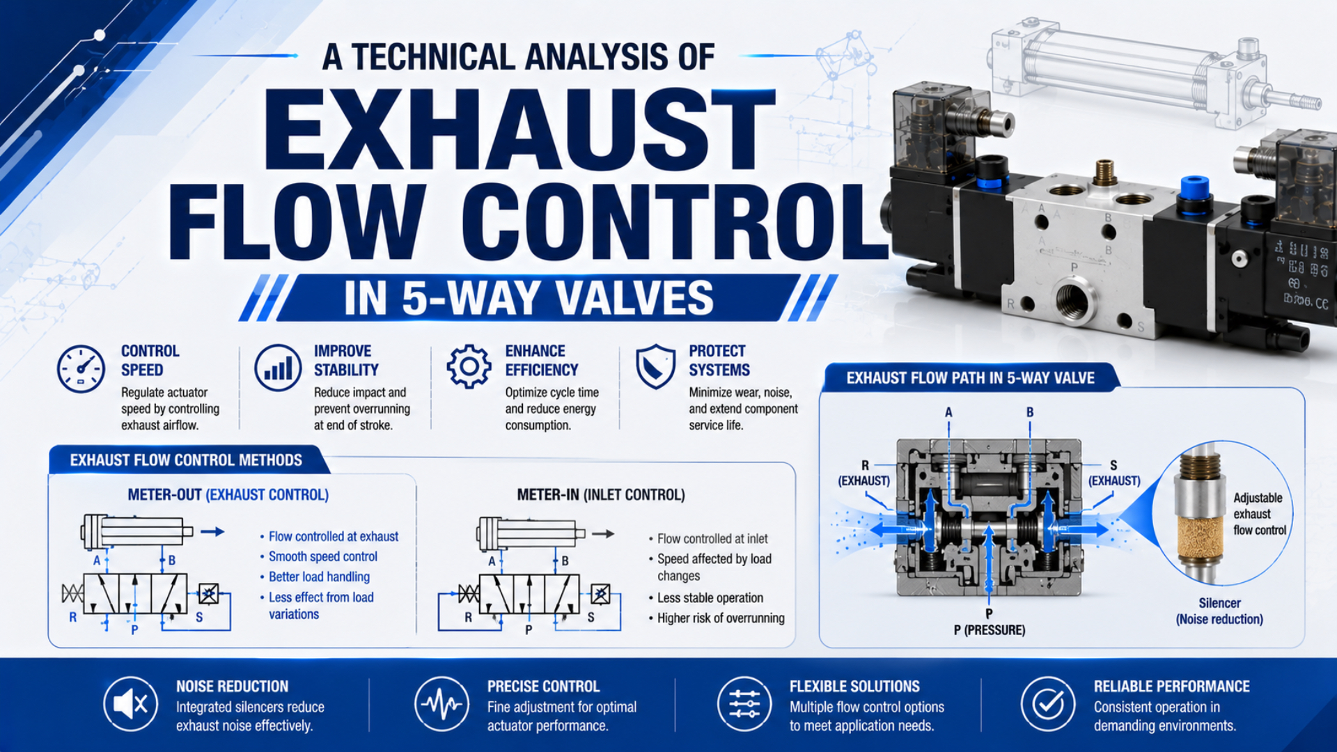
Exhaust flow control in a 5-way valve is the management of air leaving the two actuator chambers through working ports 2 and 4 and exhaust ports 3 and 5. The objective is not maximum exhaust flow in every circuit. It is enough controlled conductance to meet stroke time without losing required force, stability, cushioning, or safe stopping behavior.
A slow cylinder therefore needs a path diagnosis, not an automatic pressure increase. Record the valve symbol, active spool position, cylinder direction, inlet pressure, both chamber pressures, exhaust arrangement, and stroke time. Those measurements separate intentional meter-out control from an undersized valve passage, manifold gallery, silencer, fitting, or tube.
Key Takeaways
- A 5/2 valve has five ports and two switching positions; ports 3 and 5 are normally exhausts (Festo, accessed 2026).
- Back-pressure subtracts from cylinder force.
- Prove the limiting section with synchronized pressure and stroke-time data before changing hardware.
The useful engineering question is not “Is the exhaust large enough?” It is “Where does pressure remain above atmosphere while the piston is moving, and does that pressure fall after one controlled change?” That question turns a vague speed complaint into a testable restriction map.
How Does a 5-Way Valve Route Supply and Exhaust?
Festo explains that the first number in a directional-valve designation is the port count and the second is the switching-position count. A 5/2 valve therefore has five ports and two positions, while a 5/3 valve adds a third center position (Festo, accessed 2026).
Common ISO-style numbering used in SMC and Festo documentation is:
| Port | Common label | Function |
|---|---|---|
| 1 | P | pressure supply |
| 2 | B | working port to one actuator chamber |
| 3 | R2 or EB | exhaust associated with one working path |
| 4 | A | working port to the opposite chamber |
| 5 | R1 or EA | exhaust associated with the other working path |
In one spool position, port 1 connects to one working port while the other working port connects to an exhaust. Shifting the spool reverses those paths. Use the exact symbol on the selected valve because pilot arrangements, manifold galleries, and 5/3 center functions vary (SMC VQC4000 catalog, accessed 2026).
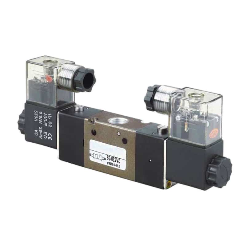
Separate exhausts are diagnostically useful. If only one direction is slow, compare the active working port, matching exhaust port, manifold passage, silencer, and speed controller for that direction. A manifold may combine exhaust galleries, so check its drawing before assuming ports 3 and 5 remain independent.
The Exhaust Path Is a Series Circuit
ISO 6358-3 provides a method for estimating the overall flow characteristics of a pneumatic system from components and piping with known characteristics. Its system-level scope matters here: valve spool windows, manifold galleries, fittings, tubes, flow controls, silencers, and cylinder ports act in series (ISO, 2014).
Air leaving a cylinder may pass through the cylinder port, a fitting, a meter-out controller, tube, directional-valve working port, spool passage, exhaust gallery, and silencer before reaching atmosphere. The narrowest effective section can dominate, but two moderate restrictions in series can also create the measured pressure loss.
Port thread size alone cannot establish exhaust capacity. ISO 6358-1 defines steady-state testing for pneumatic components with fixed or variable internal flow paths, and its published framework is a better basis for catalog comparison than external thread diameter (ISO, 2013, with 2026 uncertainty amendment).
Use the manufacturer’s directional flow data for the exact model and path. Record sonic conductance and critical pressure ratio when ISO 6358 data is available, or use the stated Cv, Kv, or rated flow only with its test pressure, downstream condition, temperature, and flow direction. Do not combine ratings from incompatible test methods as though they were the same coefficient.
For complete selection calculations, use the pneumatic flow control valve sizing guide. The port geometry and cylinder timing guide covers restrictions inside the cylinder end cap. This article keeps the boundary at the 5-way valve exhaust circuit and its measurements.
A larger directional valve cannot cancel a clogged silencer, a partially closed meter-out controller, or a small manifold gallery. Conversely, removing the silencer cannot correct a restrictive spool path. Treat every hardware change as a hypothesis about one section of the series circuit.
How Does Exhaust Back-Pressure Change Net Cylinder Force?
SMC states that cylinder force depends on pressure while speed depends on airflow, and it identifies exhaust-flow control as the common method for changing actuator speed. The resulting back-pressure is useful for motion control, but it also opposes the driving chamber (SMC, accessed 2026).
For one direction of motion, a practical force balance is:
is available force in newtons, and are simultaneous gauge pressures in pascals, and are the effective piston areas in square metres, and combines load and friction that oppose the selected direction.
An increase in exhaust pressure changes the opposing force by:
Consider a single-rod cylinder with piston diameter and rod diameter . Its full piston area is about , and its annular area is about .
If the exhausting rod-side chamber rises by during extension, the opposing-force increase is about . During retraction, the cap-end exhaust acts on the full piston area, so the same pressure increase corresponds to about . These are calculation examples, not acceptable-pressure limits.
This relationship explains why a cylinder can slow under load even when the supply gauge appears normal. It also explains why opening a meter-out control can raise speed and available force at the same time. The safe setting still depends on load direction, cushioning, impact energy, and stability.
When Is Exhaust Restriction Intentional?
Parker’s pneumatic flow-control instructions distinguish meter-in from meter-out and state that meter-out installations place the full-flow arrow toward the cylinder port. The instructions also recommend two controls for most double-acting cylinders so the two stroke directions can be adjusted independently (Parker, accessed 2026).
Meter-out control is an intentional restriction in the air leaving the active exhaust chamber. The maintained back-pressure can resist a gravity-assisted or overhauling load and make speed less sensitive to small changes in load. The adjustment is correct only when the resulting force, speed, settling, and end-of-stroke energy remain within the machine requirement.
Accidental exhaust restriction is pressure loss that the design did not request. Common locations include a clogged silencer, undersized fitting bore, long small-ID tube, incorrect one-way flow-control orientation, manifold exhaust gallery, spool passage, contaminated port, or cushion circuit that remains active too early.
One pressure trace can contain both effects. A meter-out controller may establish the intended base back-pressure while a silencer adds a second loss that grows with contamination. Record the controller position and measure before and after the valve exhaust when practical.
| Observation | More likely interpretation | Next controlled check |
|---|---|---|
| stable speed and repeatable chamber pressure | intentional meter-out action | confirm load and cushion acceptance |
| speed decreases as the silencer ages | growing unintended exhaust restriction | inspect or substitute the specified silencer |
| only one direction is slow | direction-specific working or exhaust path | compare ports 2/3 with ports 4/5 |
| cylinder runs ahead when restriction is removed | load requires controlled meter-out | restore control and review the load case |
| pressure rises only near the end of stroke | cushion passage is active | verify cushion setting and remaining travel |
The meter-in-to-meter-out retrofit guide covers conversion tests and first-stroke behavior in more detail. If the symptom is pressure remaining in a stopped system rather than pressure during motion, use the separate back-pressure troubleshooting guide.
Which Measurements Prove the Exhaust Side Is Limiting?
CAGI recommends pressure-monitoring taps because every flowing compressed-air system develops losses, and it uses 10% as a plant-level compressor-to-point-of-use design guideline. That figure is not a valve acceptance limit; machine-level diagnosis requires synchronized pressure and motion data across the suspected section (CAGI, accessed 2026).
Record these signals on the same time base:
- command to the 5-way valve and actual spool feedback when available;
- pressure at port 1 while the cylinder moves;
- pressure at both cylinder chambers;
- pressure upstream of the exhaust silencer or common manifold exhaust when accessible;
- cylinder position or timed stroke markers;
- load, direction, speed-controller setting, cushion setting, and air temperature.
Static readings after the piston stops are insufficient. Chamber and manifold pressures can equalize after flow ends, hiding the restriction that existed during motion. Use sensors with suitable pressure range, response time, sample rate, and installation volume for the transient being measured.
Pressure patterns narrow the cause. Falling port-1 pressure points upstream. High chamber pressure with low pressure at the valve exhaust points toward the working port, tube, fitting, controller, or spool route. Raised pressure at the exhaust gallery points downstream toward a common passage or silencer.
A Measurement-First Decision Sequence
ISO 6358-1 standardizes steady-state component flow testing, while real cylinder motion is transient. Use catalog conductance to screen components, then verify the installed circuit with timed strokes and dynamic pressure traces. The 2026 uncertainty amendment reinforces the need to treat measured flow data with defined uncertainty (ISO, 2026).
- Freeze the requirement. Record load, direction, target stroke time, allowable variation, end-of-stroke speed, noise constraint, and safe failure behavior.
- Map the active path. Identify ports 1, 2, 3, 4, and 5, the spool position, manifold galleries, flow-control direction, silencer, and cylinder chamber for each stroke.
- Check the supply side first. Measure port-1 pressure during motion. An upstream pressure collapse can imitate an exhaust problem.
- Capture both chamber pressures. Calculate the instantaneous force balance and identify when the exhausting chamber pressure rises.
- Measure the exhaust node. Where access permits, measure between the valve and silencer or at the common manifold exhaust.
- Make one reversible change. Substitute a known clean silencer, shorten a tube, verify controller orientation, or test another valve path.
- Repeat the same move. Compare stroke time, pressure loss, stability, and end impact. Keep the change only when all acceptance limits pass.
- Update the record. Save valve model, flow data, controller setting, sensor locations, traces, and final circuit drawing.
Do not remove an exhaust control or silencer and return the machine to production solely because the cylinder becomes faster. The change can alter running speed, impact energy, noise, contaminant exposure, and behavior under an assisting load. Complete the machine’s risk and acceptance checks before making the configuration permanent.
For pressure-drop calculations outside the valve, see how pressure drop across a pneumatic valve is calculated. If a silencer is suspected, the silencer-clogging diagnostic guide provides a maintenance-focused test sequence.
How Should Quick Exhaust, Silencers, and Meter-Out Controls Be Compared?
Parker’s quick-exhaust catalog lists model-specific capacities from 70 to 550 SCFM at its stated 100 psig inlet and full pressure-drop condition. Those figures show why catalog conditions matter: a quick exhaust can bypass a restrictive directional-valve return path, but no universal cycle-time percentage follows from the component name (Parker, accessed 2026).
| Device or change | Primary job | Useful when | Main verification |
|---|---|---|---|
| meter-out controller | regulate actuator exhaust and stabilize speed | load needs controlled motion | speed, chamber pressure, run-ahead, impact |
| exhaust silencer | reduce discharge noise and contamination ingress | open exhaust noise is unacceptable | pressure loss, noise, contamination, maintenance interval |
| larger exhaust gallery or valve path | reduce restriction inside the directional-control assembly | dynamic pressure proves that section is limiting | exact path conductance and repeated trace |
| quick exhaust valve | vent close to the actuator and bypass a long return route | directional valve or long tube is the proven exhaust limit | cracking behavior, exhaust capacity, speed, impact, noise |
| larger tube or fitting | reduce distributed or local line loss | pressure drop occurs between cylinder and valve | ID, length, fitting bore, before-and-after pressure |
A quick exhaust valve belongs close to the actuator when its purpose is to shorten the return path. It does not correct low port-1 pressure, an undersized cylinder passage, excessive load, friction, or a cushion that dominates the final stroke. It may also bypass the meter-out function that previously stabilized the load.
Check both flow directions and the device’s minimum operating differential. Confirm what happens after command removal, air loss, emergency stop, and restart. A component that makes a normal stroke faster is not automatically suitable for a safety exhaust function.
Select a quick exhaust valve only after the pressure trace locates a recoverable loss between the cylinder chamber and atmosphere. If the exhaust node is already near atmosphere while chamber pressure remains high, the restriction lies upstream of that node and a larger quick-exhaust outlet will not remove it.
See the dedicated quick-exhaust differential-speed circuit guide for port placement, flow-control location, and fault patterns. Use it with the measured restriction location, not as a default speed-up prescription.
FAQs About 5-Way Valve Exhaust Flow
SMC’s VQC4000 documentation identifies port 1 as pressure, ports 2 and 4 as working ports, and ports 3 and 5 as exhausts. Those five functions frame the questions below: each answer distinguishes the active path, intended control, and measured restriction rather than prescribing a universal port ratio (SMC, accessed 2026).
Are exhaust ports 3 and 5 always interchangeable?
No. Both are exhaust functions in common numbering, but each serves a different working-port path and may use a different spool window or manifold gallery. A manifold can also combine them. Follow the exact valve symbol and base drawing, then test extension and retraction separately before swapping silencers or controls.
Should exhaust ports be 25% larger than supply ports?
There is no universal percentage. External thread size does not define internal conductance, and each working port alternates between supply and exhaust as the valve shifts. Select the valve from manufacturer flow data at stated pressure conditions, then verify the installed supply and exhaust paths under the required load and stroke time.
Why does opening the meter-out controller increase cylinder force?
Opening the controller can reduce pressure in the exhausting chamber. That lowers the opposing term in the force balance, leaving more net force for acceleration and load. The change can also reduce motion damping, so verify run-ahead, stability, cushioning, and end impact before accepting the faster setting.
Can I diagnose exhaust restriction with a static pressure gauge?
Not reliably. The limiting pressure loss exists while air is flowing, and chamber pressure may equalize after the piston stops. Log valve command, port-1 pressure, both chamber pressures, and stroke position on the same time base. Add an exhaust-gallery measurement when the silencer or common manifold path is suspected.
When should I install a quick exhaust valve?
Install one when dynamic measurements show that the directional valve or return tubing creates the relevant exhaust loss and the application can accept the resulting speed, noise, and impact. Do not use it to mask low supply pressure, friction, excessive load, or a restrictive cylinder port. Recheck safe stopping behavior after installation.
Sources and technical references
- Festo, directional control valves, accessed 2026-07-22.
- SMC, VQC4000/5000 5-port solenoid valve catalog, accessed 2026-07-22.
- SMC, Control Air Flow of Cylinders, accessed 2026-07-22.
- Parker, Flow Control Valve Installation and Service Instructions, accessed 2026-07-22.
- Parker, Quick Exhaust and Shuttle Valve Instructions, accessed 2026-07-22.
- ISO 6358-1:2013, steady-state component flow testing, accessed 2026-07-22.
- ISO 6358-1:2013/Amd 2:2026, evaluation of measurement uncertainty, accessed 2026-07-22.
- ISO 6358-3:2014, flow characteristics of systems, accessed 2026-07-22.
- CAGI, Technical Brief on Pressure Drop, accessed 2026-07-22.