

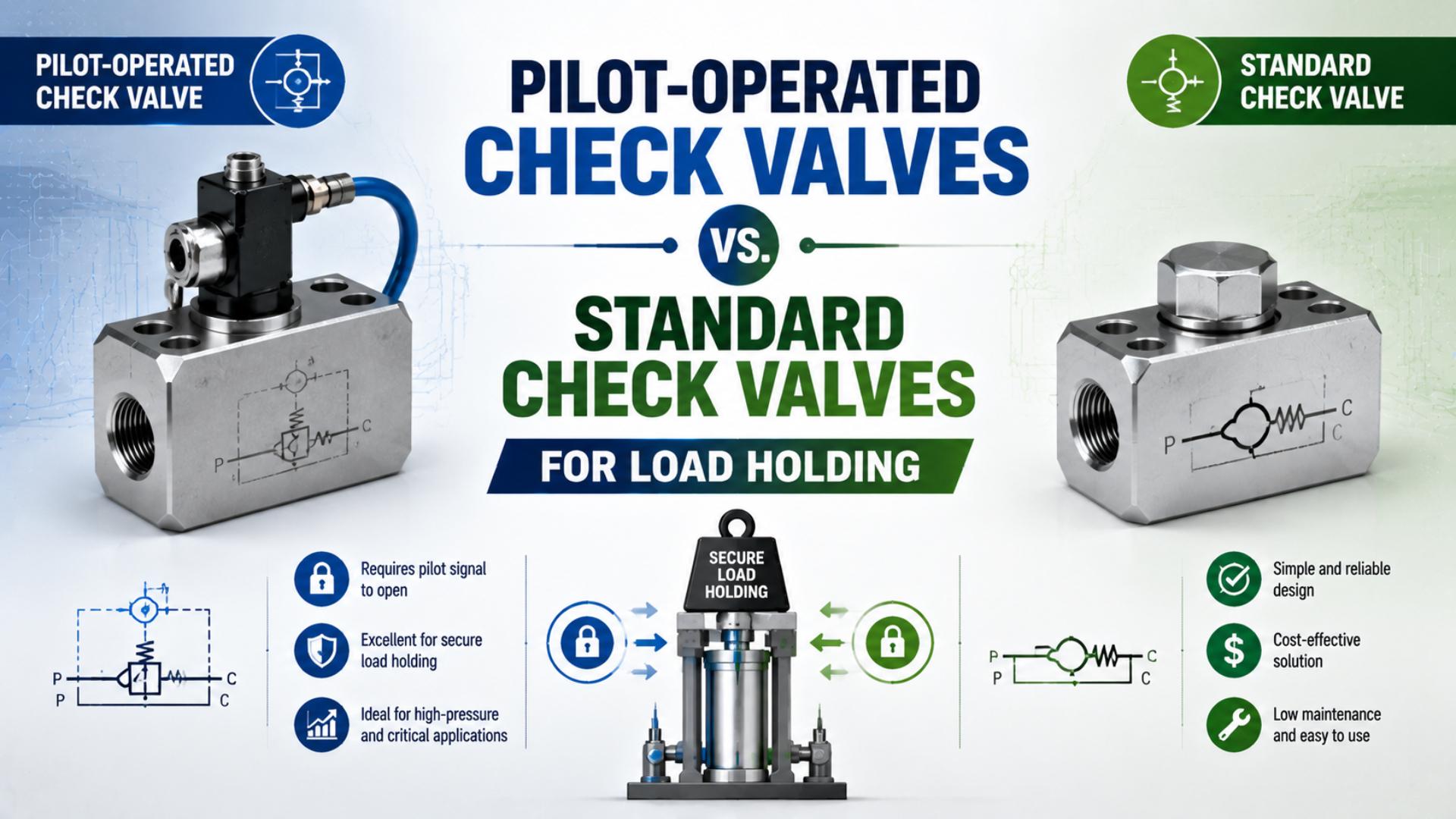
A standard check valve blocks reverse flow automatically. A pilot-operated check valve adds a pressure input that can deliberately release that blocked path. This makes the pilot-operated design useful when a cylinder chamber must remain isolated and then move on command—but it does not guarantee zero leakage, zero drift, or safe support of a suspended load.
Choose the valve from the required circuit states, allowable drift, pilot-release conditions, flow capacity, failure consequences, and maintenance procedure. If unintended motion could injure someone, the machine risk assessment may require a rod lock, brake, mechanical support, redundant safety function, or another purpose-designed restraint in addition to pneumatic valving.
Key Takeaways
- A standard check valve can retain pressure, but it cannot open the blocked direction on command.
- A pilot-operated check valve provides controlled release; the pilot normally unseats the check element rather than increasing its closing force.
- Valve leakage is only one source of cylinder drift. Cylinder seals, fittings, tubing, temperature, trapped-air compression, and external load also matter.
- ISO 4414 and ISO 13849-1 do not make a pilot-operated check valve a universal safety device.
- Verify the exact valve’s leakage, pilot-pressure, backpressure, flow, residual-pressure, and safety-use data before approval.
This article focuses specifically on the load-holding decision. For component mechanics and pilot-opening force balance, see The Engineering of Non-Return and Pilot-Operated Check Valves. For branch isolation and reverse-flow testing, use the check-valve backflow guide.
What Changes When a Check Valve Becomes Pilot Operated?
Both valve types contain a check element that permits flow in one designated direction and blocks it in the other. The difference is control over the blocked direction.
A standard check valve opens when forward pressure differential overcomes its spring, friction, and downstream pressure. Reverse pressure seats the poppet, ball, diaphragm, or other closing element. It works well for preventing backflow, isolating branches, maintaining a pressure preference, or creating a bypass around a restriction. Once reverse pressure is trapped behind it, however, the valve has no separate command input that can force the blocked path open.
A pilot-operated check valve adds a pilot piston or plunger. Adequate pilot pressure acts on that element and mechanically unseats the main check, allowing controlled reverse flow. Remove the pilot signal and the main check returns to its blocking state according to its internal design and pressure balance.
That added state is the engineering reason to use a pilot check for many clamping or cylinder-holding circuits. It is not evidence that the pilot-operated valve seals better than every standard check valve. Reverse leakage still depends on the selected product, seat design, elastomers, contamination, wear, pressure, and temperature.
| Required function | Standard check valve | Pilot-operated check valve |
|---|---|---|
| Permit normal flow in one direction | Yes | Yes |
| Automatically block designated reverse flow | Yes | Yes |
| Release the blocked path with a pneumatic command | No | Yes, if pilot force is sufficient |
| Guarantee zero reverse leakage | No | No |
| Guarantee zero cylinder drift | No | No |
| Serve as a mechanical support for personnel access | Not by valve type alone | Not by valve type alone |
Festo lists different operating-pressure, pilot-pressure, and nominal-flow values across its HGL port sizes. Its published minimum-pilot-pressure curves also change with operating pressure. These model-specific limits are why one universal “1:3” or “1:4” pilot ratio should not be copied into every design (Festo HGL datasheet, accessed 2026).
Can Either Valve Guarantee Zero Drift?
No. Even a valve documented as bubble-tight under one test method cannot guarantee that the actuator will remain at one exact position in the assembled machine.
The trapped side of a pneumatic cylinder is a system, not a single sealing interface. Position can change through:
- reverse leakage across the check valve;
- internal leakage across the piston seal;
- leakage at the rod seal, fittings, ports, or tube connections;
- hose or tube expansion and mechanical compliance;
- temperature-driven pressure change in the trapped air;
- compression or expansion caused by a changing external load;
- structural deflection in the cylinder, carriage, mount, guide, or machine frame;
- pressure equalization between two trapped cylinder chambers.
SMC explicitly warns in its ASP pilot-check documentation that pneumatic components are not guaranteed to have zero leakage, precise intermediate stops are difficult because air is compressible, and holding time depends on leakage through the valve, cylinder, and connections (SMC ASP documentation, accessed 2026).
This also explains why a pressure gauge alone cannot prove position holding. A small pressure change may produce significant motion in a lightly restrained load, while a mechanically jammed actuator may show little movement despite unacceptable leakage. Define and measure both:
- pressure retention at the relevant cylinder ports; and
- position or force retention over the required dwell time.
State the initial position, orientation, payload, supply condition, temperature range, test duration, and maximum permitted movement. “No visible drift” is not a repeatable acceptance criterion.
When Is a Pilot-Operated Check Valve the Better Choice?
Use a pilot-operated check when the circuit needs to isolate an actuator chamber during a commanded hold and later release that chamber through a defined control sequence.
Common applications include:
- clamps that must retain useful force during a short process dwell;
- cylinders that must pause while the directional valve changes state;
- circuits where loss of a pilot command should close the check path;
- actuators where the blocked direction must reopen only after the opposite chamber or another control line is pressurized;
- port-mounted isolation intended to reduce the volume exposed to downstream hose or tube failure.
A standard check valve remains appropriate when the requirement is simply one-way flow: stopping receiver backflow, separating regulator branches, protecting a vacuum line, or creating a free-flow bypass around a metering device. It may also retain pressure acceptably when reverse release is never required and its documented leakage satisfies the application. The limitation is controllability, not an automatic inability to seal.
Do not use a pilot check merely because an actuator is vertical. First define what must happen during normal stop, electrical loss, supply loss, pilot loss, tube failure, emergency stop, restart, and maintenance. In some circuits, closing a pilot check during supply loss is desirable. In others, it can leave a hazardous elevated load and compressed air trapped with no verified release method.
For intermediate production pauses that use a centered directional valve, compare this approach with the 5-way, 3-position valve holding guide. A 5/3 closed center traps air at the directional valve; a port-mounted pilot check can reduce the trapped volume, but neither arrangement converts compressed air into a rigid mechanical stop.
When Are Pneumatic Check Valves Not Enough?
A valve-only hold is not automatically an acceptable personnel-protection measure. If unintended movement can crush, shear, trap, or drop a load onto someone, use the machine risk assessment to determine the required safety function and performance.
Possible measures include:
- a cylinder with a purpose-designed rod lock;
- a spring-applied brake or mechanical latch;
- a blocking pin, prop, or maintenance support;
- a guided lifting system with a suitable load-control device;
- redundant, monitored pneumatic channels;
- position or pressure monitoring with fault detection;
- guarding that prevents access while the load can move.
The correct measure depends on the machine, load, access pattern, applicable legislation, and relevant Type-C machinery standard. A conventional pilot-operated check valve should not be called “safety rated” unless its manufacturer provides the required safety data and the complete safety function is designed and validated accordingly.
ISO 4414:2010 addresses significant hazards in pneumatic systems and gives system-level safety principles. ISO 13849-1:2023 provides a methodology for designing and integrating safety-related parts of control systems across pneumatic, electrical, mechanical, and other technologies. ISO states that ISO 13849-1 does not specify which safety functions or required performance levels apply to a particular machine. Neither standard makes a generic pilot-operated check valve mandatory for every vertical cylinder.
For servicing in workplaces covered by US requirements, OSHA 29 CFR 1910.147 treats pneumatic pressure as hazardous energy. Potentially hazardous stored or residual energy must be relieved, disconnected, restrained, or otherwise made safe, and isolation must be verified before work begins (OSHA 1910.147). A pilot check that retains pressure is therefore part of the energy-control problem as well as a possible operating solution.
How Do Pilot Pressure and Backpressure Affect Release?
The pilot signal must create enough mechanical force to unseat the main check under the worst pressure combination. The locked-port pressure is only one part of that balance. Spring force, friction, effective piston areas, pressure at the discharge port, and exhaust backpressure can all change the release threshold.
This is why a pilot ratio is not a complete selection rule. Manufacturers may define or present the ratio differently, and an ideal area ratio does not automatically include spring and friction effects. A simple calculation such as “6 bar load divided by a 3:1 ratio equals 2 bar pilot” is only acceptable if it matches the selected manufacturer’s definition and published curves.
Use this review sequence:
- Identify the pressure at every main and pilot port in each operating and fault state.
- Find the manufacturer’s minimum-pilot-pressure curve or explicit release requirement for the exact part number.
- Include downstream and exhaust backpressure rather than assuming the released side is at atmosphere.
- Check pilot pressure dynamically at the valve, not only at the regulator.
- Confirm release at the lowest supply pressure and highest expected retained-load pressure.
- Test whether the valve chatters, opens abruptly, or remains partially restricted during transition.
SMC’s ASP documentation warns that its pilot check may fail to release when pilot pressure is only 50% of operating pressure under specified conditions. SMC also offers a separate residual-pressure-release function on particular AKP models. Both examples reinforce the same rule: release behavior belongs to the exact product and circuit, not to the generic name “pilot check” (SMC ASP, SMC AKP, accessed 2026).
How Should Flow Capacity and Placement Be Evaluated?
Size the normal and released paths from the cylinder’s required free-air flow, allowable pressure loss, target stroke time, and load—not from port thread alone. A G1/4 pilot check can still be the limiting restriction if its internal flow area is smaller than the adjacent valve or fitting.
Do not compare a calculated flow in L/min directly with a dimensionless or unit-system-dependent value. First calculate the required flow, then use the manufacturer’s stated pneumatic flow method and test conditions to select a valve. Festo, for example, publishes standard nominal flow values for HGL variants rather than one family-wide capacity.
Mounting a pilot check directly at the cylinder port can reduce the trapped volume between the valve and actuator. It also reduces the length of hose or tube whose failure would bypass the holding element. That is often preferable for load retention, but it does not protect against:
- cylinder internal leakage;
- failure of the cylinder port, end cap, mount, or machine structure;
- unintended pilot pressure;
- temperature-driven pressure changes;
- unsafe motion during deliberate release.
If two pilot checks are cross-piloted from opposite cylinder lines, confirm the start sequence at low pressure. The chamber commanded to move must develop enough pressure to release the opposite check without creating excessive force or a sudden jump. Meter-out control, quick exhausts, silencers, and directional-valve center configuration can all change the transient.
How Should Trapped Energy Be Released Safely?
A closed pilot check can retain compressed air after the main supply has been isolated. A pressure gauge upstream of the check may read zero while the cylinder chamber remains pressurized.
The machine documentation should identify:
- every volume that can remain trapped;
- the device and sequence used to release or restrain that energy;
- where pressure is measured;
- how a technician verifies zero or safely controlled energy;
- how a gravity or spring load is mechanically supported before pressure is removed;
- how the system prevents unexpected motion when pressure returns.
Do not use a solenoid command or HMI indicator as proof of energy isolation. OSHA specifically distinguishes control-circuit devices from energy-isolating devices for covered servicing work. Where a manual residual-pressure release is used, position it so operating the release does not place the technician in the load path.
Release sequence matters during production too. Opening a loaded chamber directly to a low-pressure exhaust can accelerate the actuator before the opposing chamber builds pressure. Coordinate the directional valve, pilot signal, flow control, and mechanical restraint so the load remains controlled throughout the transition.
What Should a Load-Holding Acceptance Test Include?
Approve the circuit only after testing the real actuator, payload, valve, tubing, fittings, mounting, controller sequence, and environmental range.
| Test | What to record | Example acceptance basis |
|---|---|---|
| Normal hold | Both cylinder-port pressures, position, load, time, temperature | Project-defined maximum drift and force loss |
| Pilot release | Pilot pressure at the valve, retained-port pressure, opening delay, motion | Reliable release at worst permitted pressure combination |
| Flow performance | Stroke time and port pressure during extend and retract | Target time without excessive dynamic pressure loss |
| Supply loss | Valve state, load movement, retained pressure | Documented safe state for the machine |
| Pilot loss | Check state and actuator response | No unassessed motion or unstable transition |
| Tube or fitting fault | Result of the defined safe fault simulation | Risk-assessment requirement |
| Emergency stop | Stopping, holding, exhaust, and restart sequence | Validated safety specification |
| Maintenance isolation | Isolation, residual pressure, mechanical support, verification | Site energy-control procedure |
Use calibrated pressure sensors on both actuator ports and a position measurement with resolution comfortably below the allowed drift. Record valve part number, seal option, orientation, regulator setting, tube inside diameter and length, payload, cylinder position, ambient temperature, dwell time, and controller state. A video of a stationary load is not a substitute for synchronized pressure and position data.
Repeat the relevant tests after changing valve model, cylinder seals, tube length, exhaust components, load, firmware sequence, or safety architecture. If the design relies on a published leakage limit, preserve the manufacturer’s test conditions with the project record so procurement cannot replace the valve using thread size alone.
Pilot-Operated Check Valve Load-Holding FAQs
Can a standard check valve hold a pneumatic cylinder?
It can block reverse flow and may retain pressure within its documented leakage limit, but it cannot release the blocked direction on command. Cylinder position also depends on internal seal leakage, connections, trapped-air compression, temperature, and load. Use a measurable drift test rather than accepting or rejecting it solely by valve category.
Does a pilot-operated check valve provide zero-leakage holding?
Not as a generic guarantee. Check the exact model’s reverse-leakage specification and test conditions. Then test the complete assembly because cylinder, fitting, and tube leakage can still move the load even when valve leakage is very low.
What pilot ratio should be used for a pneumatic load-holding circuit?
Use the selected manufacturer’s definition, curves, and minimum-pilot-pressure requirement. Include retained pressure, discharge backpressure, spring force, friction, and the lowest dynamic pilot pressure. A universal 3:1 or 4:1 assumption is not reliable enough for final selection.
Should pilot-operated check valves be mounted at the cylinder ports?
Port mounting is often beneficial because it reduces trapped line volume and limits the tube length between the holding element and cylinder. It does not protect against cylinder internal leakage, structural failure, unintended pilot release, or every hose and fitting failure. Confirm the installation rules for the exact product.
Can a pilot-operated check valve safely support a vertical load?
Do not assume so from the valve name alone. If unexpected descent can injure someone, perform the machinery risk assessment and add the required mechanical restraint or validated safety function. Also provide a controlled method for releasing trapped pressure and supporting the load during maintenance.
Sources and technical references
- ISO 4414:2010: general rules and safety requirements for pneumatic fluid-power systems and components. Retrieved 2026-07-26.
- ISO 13849-1:2023: methodology for designing and integrating safety-related parts of control systems. Retrieved 2026-07-26.
- Festo HGL piloted check valves: port-size-specific operating pressure, pilot pressure, nominal flow, temperature, and material data. Retrieved 2026-07-26.
- Festo HGL minimum pilot-pressure curves: minimum pilot pressure as a function of operating pressure for specific HGL variants. Retrieved 2026-07-26.
- SMC ASP speed controller with pilot check: manufacturer cautions for intermediate stopping, leakage, extended holding, pilot pressure, and residual pressure. Retrieved 2026-07-26.
- SMC AKP pilot check with residual-pressure release: model-specific pilot-pressure and residual-pressure-release information. Retrieved 2026-07-26.
- OSHA 29 CFR 1910.147: control of hazardous energy for covered servicing and maintenance work. Retrieved 2026-07-26.