

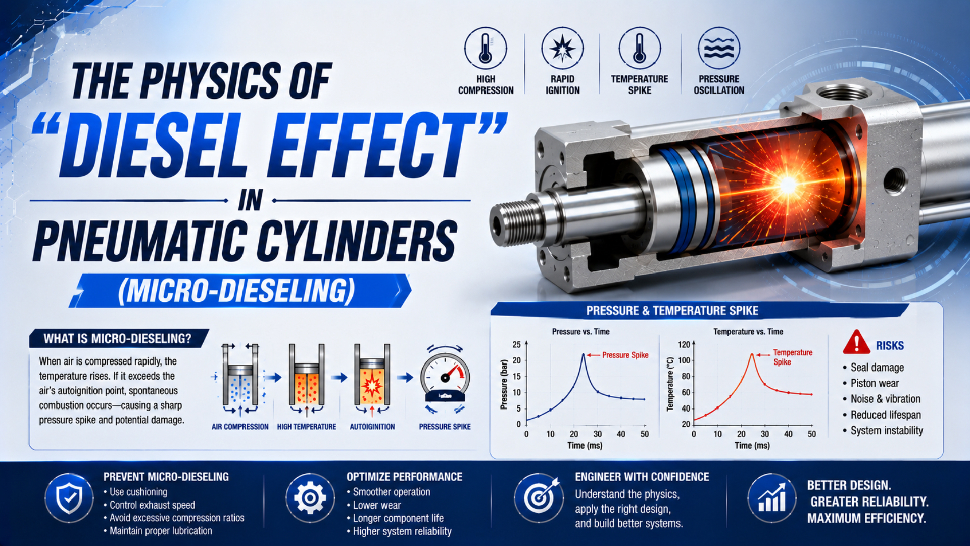
Rapid compression can heat gas enough to create an ignition hazard when combustible material is present, but a burned pneumatic-cylinder seal does not prove that micro-dieseling occurred. The defensible approach is to calculate the ideal temperature limit, reconstruct the pressure transient, identify any fuel, preserve the failed parts, and eliminate more common failure modes.
The evidence boundary matters. NASA documents rapid-pressurization ignition in high-pressure oxygen systems, while HAWE uses “diesel effect” for air bubbles compressed inside mineral oil. Neither source establishes a universal piston-speed, bore-size, or oil-concentration threshold for ordinary industrial air cylinders (NASA, 2016; HAWE).
Key Takeaways
- An ideal 8:1 pressure ratio raises air from 20°C to about 258°C, not 520°C.
- Use absolute pressure and absolute temperature in the calculation.
- Soot, odor, or a black seal is evidence to preserve, not proof of ignition.
- No validated universal 2 m/s micro-dieseling threshold applies to pneumatic cylinders.
What Does “Diesel Effect” Mean in a Pneumatic Cylinder?
NASA describes rapid pressurization in less than 1 second as an ignition mechanism when compressed gas heats nearby combustible material. HAWE documents a related hydraulic mechanism in aerated mineral oil. For an ordinary pneumatic cylinder, “diesel effect” is therefore a hypothesis that requires physical evidence, not an automatic diagnosis (NASA, 2007; HAWE).
Rapid-pressurization ignition is ignition caused when gas compression heats a nearby combustible material. Air is the oxidizer in a normal pneumatic circuit; it is not the fuel. A plausible scenario also requires a combustible vapor, aerosol, droplet, film, seal fragment, cleaning solvent, or other residue at a location where the transient gas temperature exceeds that material’s situational ignition threshold.
Three contexts are often grouped under one label even though their operating conditions differ sharply:
| Context | Compressed phase | Potential fuel | What the cited evidence establishes |
|---|---|---|---|
| Aerated hydraulic oil | Air or vapor bubbles inside liquid oil | Oil surrounding the bubble | Local self-ignition and oil or seal damage are recognized hydraulic mechanisms |
| High-pressure oxygen hardware | Oxygen trapped in a dead end | Exposed nonmetal or contamination | Rapid pressurization is a documented oxygen-system ignition mechanism |
| Industrial pneumatic cylinder | Air in a changing, valve-connected chamber | Lubricant or process contamination | Mechanism is physically possible, but diagnosis requires incident-specific evidence |
This distinction prevents a common analytical mistake: using data from high-pressure oxygen equipment to assign a fixed safe speed to a 6 or 8 bar air cylinder. ISO 4414 covers significant hazards in pneumatic systems, but it does not publish a “micro-dieseling” velocity chart (ISO 4414, 2010).
Name the control volume before naming the failure mechanism. A trapped pocket at a closed end, an actively filling cylinder chamber, and an air bubble surrounded by hydraulic oil have different mass, heat-transfer, and reaction boundaries. The label alone cannot make their evidence interchangeable.
How Hot Can Ideal Adiabatic Compression Make the Air?
NASA’s ideal relation requires absolute pressure and temperature. It uses a specific-heat ratio of about 1.4. Starting at 293 K, an 8:1 ideal pressure ratio gives 530.8 K, or 257.6°C, not 520°C. This fixed-mass result is a screening limit, not a measured cylinder temperature (NASA, 2007).
For an ideal, reversible adiabatic compression of a fixed gas mass:
Here, and are absolute temperatures, and are absolute pressures, and is the ratio of specific heats. All pressure readings must first be converted to absolute pressure:
For air initially at 20°C and 1 bar absolute, the ideal endpoint changes as follows:
| Absolute pressure ratio | Ideal final temperature |
|---|---|
| 1:1 | 20.0°C |
| 2:1 | 84.0°C |
| 4:1 | 162.3°C |
| 6:1 | 215.7°C |
| 8:1 | 257.6°C |
| 10:1 | 292.5°C |
The calculation contains no time term. A fast event makes the no-heat-transfer assumption more plausible, but pressure ratio determines the ideal endpoint. Real cylinder filling is an open-system transient: air enters through a restriction, chamber volume can change, heat reaches the wall, leakage occurs, and temperature is spatially uneven. NASA states that actual maximum temperature is appreciably lower than the ideal maximum in real hardware.
The related adiabatic expansion model shows the same limitation from the cooling side. A polytropic process model can represent a defensible fixed-mass interval, but it does not convert an actively valve-connected stroke into a closed system.
Why Is There No Universal Speed or Oil-Concentration Threshold?
ISO 8573-1 separates 3 primary contaminant groups: particles, water, and oil. ISO 8573-2 measures liquid oil and aerosol; ISO 8573-5:2025 covers oil vapor. These standards define air-quality measurement, not universal piston-speed, bore, or total-oil ignition limits for pneumatic-cylinder micro-dieseling (ISO 8573-1, 2010; ISO 8573-2, 2018; ISO 8573-5, 2025).
Piston velocity is not compression rate. A piston moving quickly in a freely exhausting chamber may not compress a trapped pocket severely. A slower motion toward a blocked or badly timed port can create a larger pressure ratio in a small dead volume. Valve opening profile, cushion geometry, exhaust back pressure, load direction, seal leakage, and initial chamber pressure all influence the transient.
Oil content also needs more definition. An aerosol measurement does not identify a pooled lubricant film, cleaning-solvent residue, seal additive, or process hydrocarbon deposited at one end cap. Conversely, visible oil does not show that a combustible mixture existed at the moment of failure. Use the lubricant’s current safety data sheet and application approval rather than a generic mineral-versus-synthetic temperature table.
| Required input | Why it changes the analysis | How to obtain it |
|---|---|---|
| Initial and final chamber pressure | Establishes the actual absolute pressure ratio | Synchronized pressure sensors at the cylinder ports |
| Pressurization time and valve command | Defines the transient rather than piston speed alone | Controller trace plus high-rate pressure acquisition |
| Trapped or dead volume | Locates the gas being compressed | Cylinder drawing, valve state, tubing volume, piston position |
| Oil aerosol, liquid oil, and vapor | Separates contaminant phases | ISO 8573-2 and ISO 8573-5 methods at the stated sampling point |
| Residue identity | Tests whether a plausible fuel was present | Controlled laboratory analysis of preserved material |
| Material ignition behavior | Depends on compound and atmosphere | Manufacturer data or a relevant standardized test |
A useful screening parameter is the local pressure-time history, not the catalog piston speed. The same rod velocity can accompany chamber filling, free exhaust, cushion compression, or compression against a blocked path. Those events do not share one temperature history.
For a broader air-quality specification, use the ISO 8573-1 compressed-air guide. If the concern is motion rather than ignition, calculate and measure pneumatic-cylinder piston velocity separately.
Evidence That Supports a Compression-Ignition Diagnosis
ISO 4414:2010 addresses significant pneumatic-system hazards, but it provides no single visual test for micro-dieseling. A credible diagnosis needs 4 converging evidence groups: the incident sequence, pressure and valve data, chemical or thermal residue, and documented exclusion of plausible alternative failures (ISO 4414, 2010).
Visible damage should be interpreted cautiously:
| Observation | What it can support | What it cannot prove alone |
|---|---|---|
| Black, brittle seal | Severe heat, oxidation, chemical degradation, or aging | That combustion occurred inside the chamber |
| Soot-like deposit | Carbonaceous residue may be present | Its source, age, or ignition location |
| Blue, brown, or black metal | A surface experienced a thermal or chemical change | A precise peak temperature |
| Blown seal or end-cap damage | An abnormal pressure or mechanical load occurred | That pressure came from combustion |
| Acrid odor or reported smoke | A thermal event deserves investigation | The fuel, reaction, or point of origin |
Metal color cannot serve as a thermometer because alloy, anodizing, plating, prior finish, atmosphere, heating time, and contamination all affect it. Photograph the part under controlled lighting, then preserve it. Do not polish or solvent-clean the surface before an investigator decides what samples are needed.
Alternative causes deserve equal attention. Seal extrusion can create ragged, locally overheated edges; side load can generate friction and rod-seal damage; incompatible chemicals can harden or blacken elastomers; and external heat or electrical faults can produce misleading deposits. Compare the evidence with the extrusion-gap failure mechanism and rod-bearing side-load analysis before assigning a combustion cause.
How Should a Suspected Incident Be Investigated?
OSHA explicitly includes pneumatic energy among hazardous energy sources. The same rule also covers thermal energy and requires the applicable control procedure to isolate a failed machine and render stored energy safe. Until structural integrity has been assessed, a suspected ignition or overpressure event also warrants an exclusion zone (OSHA).
Follow the site’s incident and lockout procedures. A useful engineering sequence is:
- Protect people first. Stop operation and keep personnel clear. Use the site emergency plan for fire, smoke, structural, or process hazards.
- Control every energy source. Isolate pneumatic, electrical, mechanical, gravitational, hydraulic, chemical, and thermal energy. Relieve, restrain, block, or otherwise make residual energy safe. Verify isolation at the machine instead of relying on a control-screen indication.
- Do not cycle the circuit. A restart can destroy evidence or repeat the hazardous event.
- Record the sequence. Preserve controller logs, alarm history, valve outputs, supply pressure, port pressure, piston position, cycle count, ambient conditions, and witness observations.
- Document before disassembly. Photograph the complete installation, tubing, valves, speed controls, cushions, exhaust devices, regulator settings, and failed component orientation.
- Preserve residues and parts. Bag and label components separately. Record who handled them. Do not wipe, scrape, sand, or wash the suspected surfaces.
- Engage the right specialists. Structural damage, fire evidence, oxygen enrichment, personal injury, or regulatory reporting can require the machine builder, component manufacturer, insurer, laboratory, or qualified failure investigator.
Synchronize the pressure record with valve commands and piston position because supply pressure alone cannot show what happened in a dead-end pocket. Measure at the relevant chamber port. Select a sensor and sample rate suitable for the event, then state the range, location, accuracy, and synchronization method. Another engineer must be able to judge the trace.
Before returning the machine to service, document the identified cause, corrective action, changed drawings or settings, acceptance test, and responsible approver. If the evidence remains inconclusive, say so. “Undetermined” is safer than converting an attractive theory into a maintenance standard.
A Prevention Hierarchy for Pneumatic Cylinder Circuits
ISO 12100:2010 defines machinery risk assessment. ISO 4414 applies corresponding safety principles to pneumatic systems. Prevention should remove unintended combustible contamination, control the pressurization path, enforce component limits, and monitor hazard-related variables. A fixed 2 m/s cap is not a prevention hierarchy (ISO 12100, 2010; ISO 4414, 2010).
- Remove unintended fuel sources. Eliminate unapproved oils, solvent residue, cross-contamination, and excessive lubricator delivery. Use only media and lubricants approved by the component manufacturer.
- Specify air quality at the point of use. State the ISO 8573-1 purity class needed for the application and use the relevant measurement method for aerosol, liquid oil, and vapor. A compressor-room specification does not prove cylinder-port conditions.
- Control initial pressurization. Evaluate a soft-start or staged-fill function within the machine’s risk assessment. Confirm that it controls the actual downstream volume and does not create unexpected actuator motion.
- Review trapped volumes and valve states. Check cushions, blocked ports, pilot timing, check valves, exhaust restrictions, silencers, tubing pockets, and maintenance bypasses.
- Stay inside verified limits. Follow the cylinder, valve, seal, tubing, regulator, and lubricant manufacturers’ pressure, temperature, speed, media, and installation limits.
- Instrument the real event. Where risk assessment identifies a credible hazard, trend port pressure, supply pressure, position, valve command, and temperature with response times suited to the transient.
- Control modifications. Reassess risk after changing a valve, flow control, cushion, lubricant, compressor, filter, cycle time, cylinder size, or control sequence.
Self-lubricating seals can reduce the need for externally added oil, but they do not make a circuit contamination-proof. Match the compound and lubrication strategy to the manufacturer guidance described in the self-lubricating seal guide.
Neither cylinder category has an inherent advantage. Dead volume, port geometry, sealing concept, cushion design, load, speed profile, and valve path vary by model. Compare actual drawings and transient measurements instead of assigning a risk level to the entire cylinder category.
Treat the startup pressure path as a design state, not a commissioning detail. Many analyses cover steady cycling but omit what happens after maintenance, an emergency stop, a vented manifold, a stuck piston, or a partially pressurized branch. Those states can create the largest local pressure ratio.
What Changes for Oxygen-Enriched Service?
NASA identifies 3 characteristic conditions for rapid-pressurization ignition in oxygen hardware: fast pressurization, an exposed nonmetal near the compressed dead end, and a pressure ratio capable of exceeding that material’s situational autoignition temperature. This is a specialized oxygen-compatibility problem, not an ordinary pneumatic-cylinder lubrication problem (NASA, 2007).
Ordinary air-service rules are insufficient. Do not transfer their components, oils, cleaning agents, filters, seal rules, or speed limits into oxygen-enriched service. Oxygen compatibility depends on concentration, pressure, temperature, cleanliness, particle generation, geometry, material configuration, ignition mechanisms, and credible fault states. “Oil-free” does not mean oxygen-clean, and a material described as nonflammable in air can behave differently in oxygen.
NASA’s White Sands Test Facility lists rapid pressurization, mechanical impact, particle impact, friction, and electrical arc among ignition mechanisms evaluated for oxygen systems. Each mechanism has its own test approach (NASA WSTF, 2016).
Use a qualified oxygen-system specialist and the standards required by the jurisdiction, equipment owner, and application. The review should define compatible materials, cleaning level, assembly controls, operating procedure, pressurization rate, component testing, inspection, and change management. General pneumatic advice is not an acceptable substitute.
Pneumatic Cylinder Diesel Effect FAQs
ISO 4414 covers pneumatic hazards, ISO 8573 separates 3 primary compressed-air contaminant groups, and NASA distinguishes ideal from actual hardware temperature. The practical rules are concise: use absolute values for screening, measure the transient, preserve evidence, and reject universal speed or oil thresholds (ISO 4414, 2010; ISO 8573-1, 2010; NASA, 2007).
Can diesel effect occur in a standard 6 to 8 bar pneumatic cylinder?
Rapid compression heats trapped gas. A physically possible ignition also requires combustible material and suitable local conditions. Published oxygen and hydraulic evidence supplies neither an incident rate nor a universal threshold for standard air cylinders. Treat each suspected case as a failure investigation, not a diagnosis based only on operating pressure.
Do blackened seals prove micro-dieseling?
No. Blackening, brittleness, odor, smoke, and deposits justify preserving the parts and investigating a thermal event, but they do not identify the heat source. Chemical attack, friction, external heat, electrical faults, aging, and residue from the process can create overlapping signs. Chemical, microscopic, pressure, and sequence evidence must converge.
Is a piston-speed limit enough to prevent compression ignition?
No validated universal piston-speed limit defines the boundary. Local pressure ratio and pressurization time depend on valve state, trapped volume, exhaust restriction, cushion geometry, piston position, and initial pressure. Use manufacturer speed limits for motion design, then assess rapid pressurization separately through pressure-time measurements and the machine risk assessment.
Does an oil-free compressor eliminate the risk?
No. It removes one potential source of compressor lubricant, but downstream piping, assembly grease, cleaning solvents, process aerosols, seal materials, and maintenance contamination remain relevant. Specify compressed-air purity at the point of use and measure oil aerosol, liquid oil, and vapor with the appropriate ISO 8573 methods.
Are rodless cylinders inherently safer from micro-dieseling?
No cylinder category has a universal advantage. A rodless design can have different port, cushion, seal, and dead-volume geometry, but those details vary by model. Compare the actual pressure-time history, contaminant control, valve path, manufacturer limits, and credible fault states for the two candidate designs under the same application conditions.
Sources and technical references
- NASA, Safety Standard for Oxygen and Oxygen Systems, NASA/TM-2007-213740, rapid-pressurization ignition mechanism and ideal temperature relation. Accessed 2026-07-26.
- NASA White Sands Test Facility, Ignition Susceptibility and Flammability, oxygen-system ignition mechanisms and test methods. Accessed 2026-07-26.
- NASA, Thermodynamic and Fluid Mechanic Analysis of Rapid Pressurization in a Dead-End Tube, transient dead-end oxygen pressurization models. Accessed 2026-07-26.
- MIT OpenCourseWare, Lecture 7: Ideal Gas Processes, ideal-gas process boundaries. Spring 2021.
- HAWE Hydraulik, Diesel Effect, hydraulic definition involving rapid compression of air bubbles in mineral oil. Accessed 2026-07-26.
- ISO, ISO 4414:2010, general rules and safety requirements for pneumatic systems and components. Accessed 2026-07-26.
- ISO, ISO 12100:2010, machinery risk assessment and risk reduction. Accessed 2026-07-26.
- ISO, ISO 8573-1:2010, compressed-air contaminants and purity classes. Accessed 2026-07-26.
- ISO, ISO 8573-2:2018, liquid-oil and oil-aerosol measurement. Accessed 2026-07-26.
- ISO, ISO 8573-5:2025, oil-vapor measurement by pressurized sampling and gas chromatography. Accessed 2026-07-26.
- OSHA, 29 CFR 1910.147: The Control of Hazardous Energy, energy-control requirements that include pneumatic and thermal energy. Accessed 2026-07-26.