Every maintenance engineer’s nightmare is unexpected equipment failure. When machines vibrate at their natural frequency, catastrophic damage can occur within minutes. I’ve seen this problem cost companies thousands in downtime.
Vibration resonance1 occurs when an external force matches a system’s natural frequency, causing amplified oscillations that can damage equipment. Understanding and controlling this phenomenon is essential for preventing failures and extending machinery lifespan.
Let me share a quick story. Last year, a customer from Germany called me in a panic. Their production line had stopped because a kolbenstangenloser Zylinder was vibrating violently. The problem? Resonance. By the end of this article, you’ll understand how to identify and prevent similar issues in your systems.
Inhaltsübersicht
- Natural Frequency Formula: How Can You Calculate Your System’s Vulnerable Points?
- Mass-Spring Model: Why Is This Simplified Approach So Valuable?
- Damping Ratio Optimization: What Experiments Yield the Best Results?
- Schlussfolgerung
- FAQs About Vibration Resonance
Natural Frequency Formula: How Can You Calculate Your System’s Vulnerable Points?
Understanding your equipment’s natural frequency is the first step toward preventing resonance issues. This critical value determines when your system is most vulnerable to vibration problems.
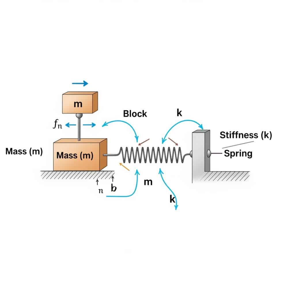
Die natural frequency2 (fn) of a system can be calculated using the formula: fn = (1/2π) × √(k/m), where k is the stiffness coefficient and m is the mass. This calculation reveals the frequency at which your system will resonate if excited by matching external forces.

When I visited a manufacturing plant in Switzerland, I noticed their rodless pneumatic cylinders were failing prematurely. Their maintenance team hadn’t calculated the natural frequency of their setup. After applying this formula, we identified that their operating speed was dangerously close to the system’s natural frequency.
Practical Applications of Natural Frequency Calculations
The natural frequency formula isn’t just theoretical—it has direct applications in various industrial settings:
- Equipment Selection: Choosing components with natural frequencies far from your operating conditions
- Preventive Maintenance: Scheduling inspections based on vibration risk profiles
- Troubleshooting: Identifying the root cause of unexpected vibrations
Common Natural Frequency Values for Industrial Components
| Komponente | Typical Natural Frequency Range (Hz) |
|---|---|
| Kolbenstangenlose Zylinder | 10-50 Hz |
| Montagebügel | 20-100 Hz |
| Support Structures | 5-30 Hz |
| Control Valves | 40-200 Hz |
Critical Factors Affecting Natural Frequency
The natural frequency calculation seems simple, but several factors can complicate real-world applications:
- Non-uniform mass distribution: Most industrial components don’t have perfectly distributed mass
- Variable stiffness: Components may have different stiffness in different directions
- Connection points: How components are mounted significantly affects their vibration characteristics
- Temperature effects: Both mass and stiffness properties can change with temperature
Mass-Spring Model: Why Is This Simplified Approach So Valuable?
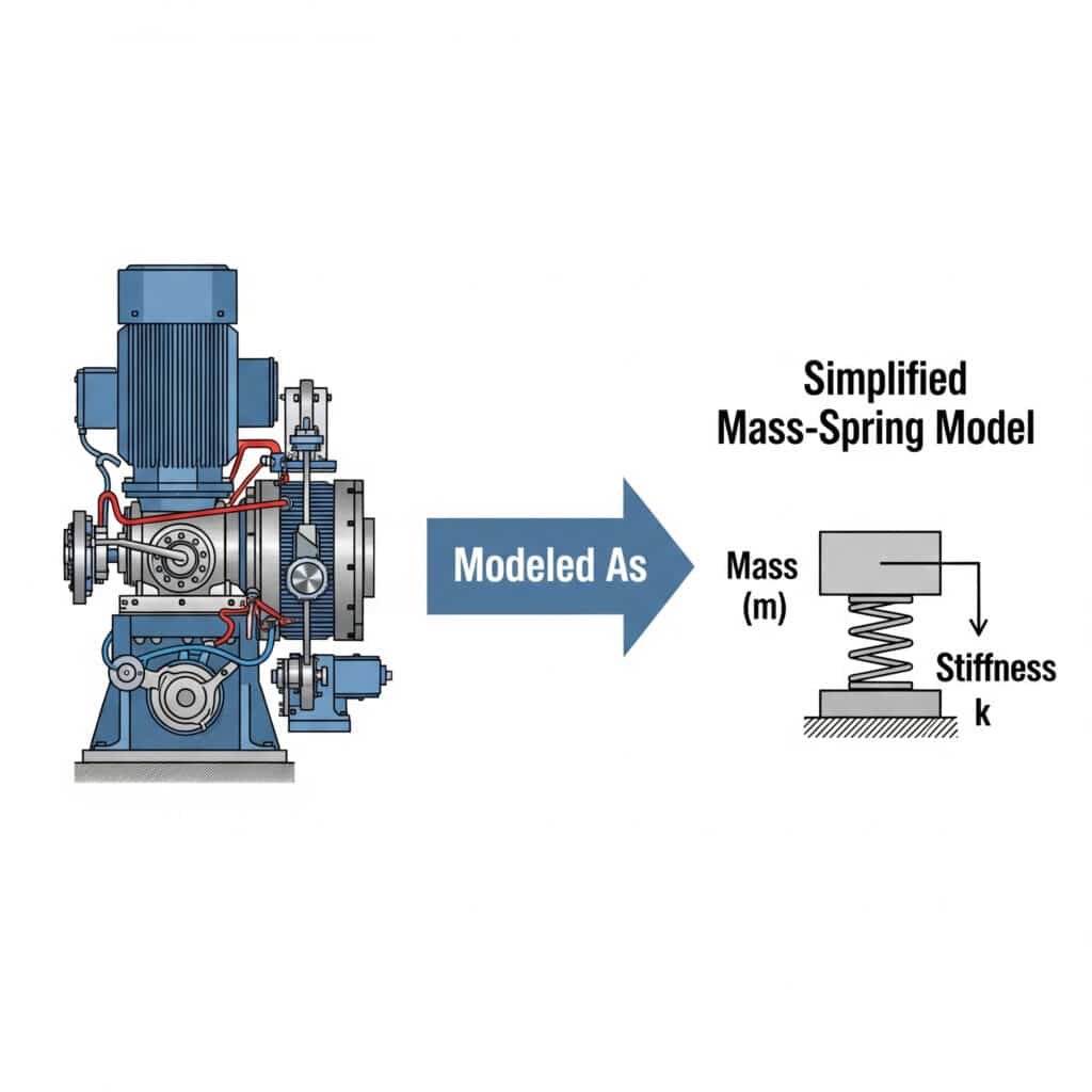
The mass-spring model provides an intuitive framework for understanding complex vibration systems. It reduces complicated machinery to basic elements that engineers can easily analyze.
Die mass-spring model3 simplifies vibration analysis by representing mechanical systems as discrete masses connected by springs. This approach allows engineers to predict system behavior, identify potential resonance issues, and develop effective solutions without complex mathematics.

I remember working with an automotive parts manufacturer in Michigan who couldn’t understand why their guided rodless cylinders were failing. By modeling their system as a simple mass-spring arrangement, we identified that the mounting brackets were acting as unintended springs, creating a resonance condition.
Converting Real Systems to Mass-Spring Models
To apply this approach to your equipment:
- Identify key masses: Determine which components contribute significant weight
- Locate spring elements: Find components that store and release energy (actual springs, flexible mounts, etc.)
- Map connections: Document how masses and springs interact
- Simplify: Combine similar elements to create a manageable model
Types of Mass-Spring Systems
| System Type | Description | Gemeinsame Anwendungen |
|---|---|---|
| Single DOF | One mass with one spring | Simple pneumatic cylinders |
| Multi-DOF | Multiple masses with multiple springs | Complex machinery with multiple components |
| Continuous | Infinite DOF (requires different analysis) | Beams, plates, and shells |
Advanced Modeling Considerations
While the basic mass-spring model is valuable, several enhancements make it more realistic:
- Adding dampers: Real systems always have energy dissipation
- Considering nonlinearities: Springs don’t always follow Hookesches Gesetz4 perfectly
- Accounting for forced vibration: External forces change system behavior
- Including coupling effects: Movement in one direction can affect other directions
Damping Ratio Optimization: What Experiments Yield the Best Results?
Damping is your best defense against resonance problems. Finding the optimal damping ratio through experimentation can dramatically improve system performance and reliability.
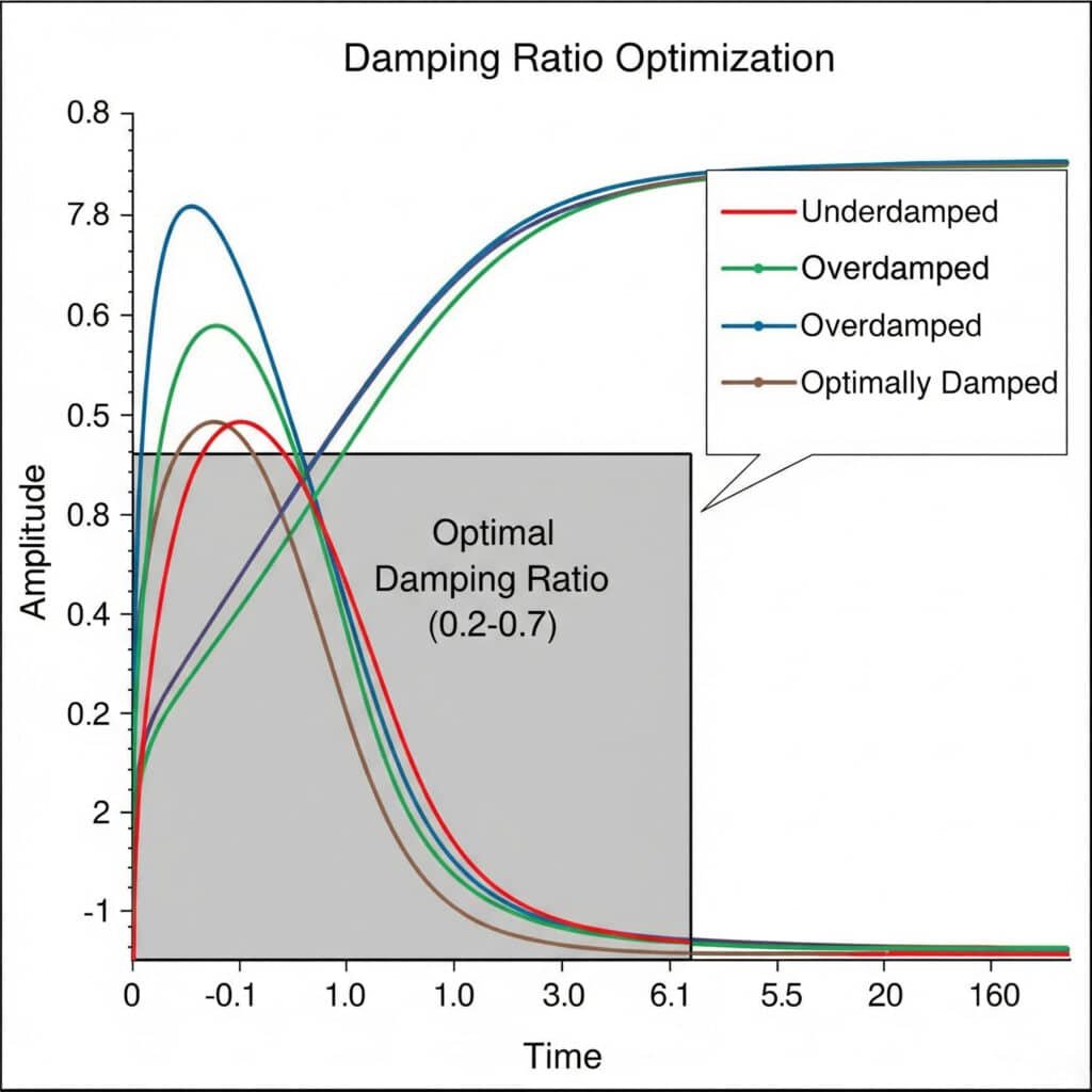
Damping ratio5 optimization experiments involve systematically testing different damping configurations to find the ideal balance between vibration control and system responsiveness. The optimal damping ratio typically falls between 0.2 and 0.7, providing sufficient vibration suppression without excessive energy loss.

Last month, I helped a food processing equipment manufacturer in France solve persistent vibration issues in their magnetic rodless cylinders. Through a series of damping ratio experiments, we discovered that their original design had a damping ratio of only 0.05—far too low to prevent resonance problems.
Experimental Setup for Damping Ratio Testing
To conduct effective damping optimization experiments:
- Baseline measurement: Record system response without additional damping
- Incremental testing: Add damping elements in controlled increments
- Response measurement: Measure amplitude, settling time, and frequency response
- Data analysis: Calculate damping ratio for each configuration
- Validation: Verify performance under actual operating conditions
Damping Technologies Comparison
| Damping Technology | Vorteile | Beschränkungen | Typical Applications |
|---|---|---|---|
| Viscous Dampers | Predictable performance, temperature stable | Require maintenance, potential leaks | Heavy machinery, precision equipment |
| Friction Dampers | Simple design, cost-effective | Wear over time, nonlinear behavior | Structural supports, basic machinery |
| Material Damping | No moving parts, compact | Limited adjustment range | Precision instruments, vibration isolation |
| Active Damping | Adaptable to changing conditions | Complex, requires power | Critical applications, variable-speed equipment |
Optimizing Damping for Different Operating Conditions
The ideal damping ratio isn’t universal—it depends on your specific application:
- High-speed operations: Lower damping ratios (0.1-0.3) maintain responsiveness
- Precision applications: Higher damping ratios (0.5-0.7) provide stability
- Variable-load systems: Adaptive damping may be necessary
- Temperature-sensitive environments: Consider damping materials with stable properties
Case Study: Rodless Cylinder Damping Optimization
When optimizing a double-acting rodless cylinder for a packaging machine, we tested five different damping configurations:
- Standard end cushions: Damping ratio = 0.12
- Extended cushions: Damping ratio = 0.25
- External shock absorbers: Damping ratio = 0.41
- Composite mounting brackets: Damping ratio = 0.38
- Combined approach (3+4): Damping ratio = 0.53
The combined approach provided the best performance, reducing vibration amplitude by 78% while maintaining acceptable response times.
Schlussfolgerung
Understanding vibration resonance through natural frequency calculations, mass-spring modeling, and damping ratio optimization is crucial for preventing equipment failures. By applying these principles, you can extend machinery life, reduce downtime, and improve overall system performance.
FAQs About Vibration Resonance
What is vibration resonance in industrial equipment?
Vibration resonance occurs when an external force matches a system’s natural frequency, causing amplified oscillations. In industrial equipment, this phenomenon can lead to excessive movement, component fatigue, and catastrophic failures if not properly managed.
How can I identify if my system is experiencing resonance?
Look for symptoms like unexplained noise increases, visible vibration at specific speeds, premature component failures, and performance degradation that occurs at consistent operating points. Vibration analysis tools can confirm resonance conditions.
What’s the difference between forced vibration and resonance?
Forced vibration occurs whenever an external force acts on a system, while resonance is the specific condition when that forcing frequency matches the system’s natural frequency, resulting in amplified response. All resonance involves forced vibration, but not all forced vibration causes resonance.
How does a rodless pneumatic cylinder’s design affect its vibration characteristics?
The design of rodless pneumatic cylinders—with their moving carriage, internal sealing system, and guide mechanisms—creates unique vibration challenges. The extended profile acts as a beam that can flex, the carriage mass creates inertial forces, and the sealing bands can introduce variable friction.
What simple modifications can reduce resonance in existing equipment?
For existing equipment experiencing resonance issues, consider adding mass to change the natural frequency, installing external dampers or shock absorbers, modifying mounting methods to include vibration isolation, or adjusting operating speeds to avoid resonant frequencies.
-
Provides a foundational explanation of mechanical resonance, often with visual examples, demonstrating how a small periodic force can produce large-amplitude oscillations in a system. ↩
-
Offers a detailed look into the physics of natural frequency, the specific frequency at which a system tends to oscillate in the absence of any driving or damping force. ↩
-
Explains the principles of the mass-spring model, a fundamental idealization in physics and engineering used to analyze complex systems that exhibit simple harmonic motion. ↩
-
Details Hooke’s Law, a principle of physics that states the force needed to extend or compress a spring by some distance is directly proportional to that distance. ↩
-
Describes the damping ratio, a dimensionless measure that defines how oscillations in a system decay after a disturbance, which is critical for controlling resonance. ↩


