

Are you struggling with pneumatic system failures or inefficient operations? The problem often lies in improper actuator selection, leading to decreased productivity and increased maintenance costs. A properly selected pneumatic actuator can solve these issues immediately.
The right pneumatic actuator should match your application’s force requirements, speed needs, and load conditions while considering environmental factors and longevity. Selection requires understanding force calculations, load matching, and special application requirements.
Let me share something from my 15+ years in the pneumatic industry. Last month, a customer from Germany saved over $15,000 in downtime costs by correctly selecting a replacement rodless cylinder instead of waiting weeks for the OEM part. Let’s explore how you can make similar smart choices.
Inhaltsübersicht
- Force and Speed Calculation Formulas
- Rod End Load Matching Reference Tables
- Anti-rotation Cylinder Application Analysis
How Do You Calculate the Force and Speed of a Pneumatic Cylinder?
When selecting a pneumatic actuator, understanding the force and speed relationship is crucial for optimal performance in your application.
The force of a pneumatic cylinder is calculated using the formula F = P × A, where F is force (N), P is Druck1 (Pa), and A is the effective piston area (m²). Speed depends on flow rate and can be estimated with v = Q/A, where v is velocity, Q is flow rate, and A is piston area.
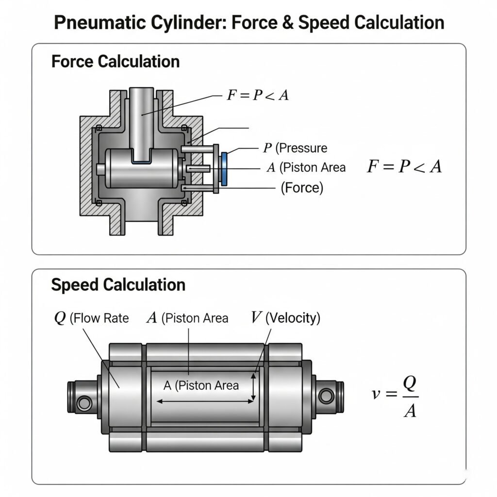
Basic Force Calculation Formulas
The force calculation differs between the extension and retraction strokes due to the difference in effective areas:
Extension Force (Forward Stroke)
For the extension stroke, we use the full piston area:
F₁ = P × π × (D²/4)
Wo:
- F₁ = Extension force (N)
- P = Operating pressure (Pa)
- D = Piston diameter (m)
Retraction Force (Return Stroke)
For the retraction stroke, we must account for the rod area:
F₂ = P × π × (D² – d²)/4
Wo:
- F₂ = Retraction force (N)
- d = Rod diameter (m)
Speed Calculation and Control
The speed of a pneumatic cylinder depends on:
- Air flow rate
- Cylinder bore size
- Load conditions
The basic formula is:
v = Q/A
Wo:
- v = Geschwindigkeit (m/s)
- Q = Durchflussmenge (m³/s)
- A = Kolbenfläche (m²)
For kolbenstangenlose Zylinder2 like our Bepto models, the speed calculation is more straightforward since the effective area remains constant in both directions.
Practical Example
Let’s say you need to move a 50kg load horizontally with a 40mm bore rodless cylinder at 6 bar pressure:
- Calculate force: F = 6 × 10⁵ × π × (0.04²/4) = 754 N
- With 50kg load (490N) and friction, this provides adequate force
- For speed of 0.5 m/s with this bore, you’d need approximately 38 L/min of air flow
Remember that these calculations provide theoretical values. In real-world applications, you should account for:
- Reibungsverluste3 (typically 10-30%)
- Pressure drops in the system
- Dynamic load conditions
What Rod End Load Specifications Should Match Your Application Requirements?
Selecting the right rod end load capacity prevents premature wear, binding, and system failure in pneumatic systems.
Rod end load matching requires comparing your application’s side loads, moment loads, and axial loads4 with the manufacturer’s specifications. For rodless cylinders, the load carrying capacity of the bearing system is critical as it directly impacts cylinder life and performance.
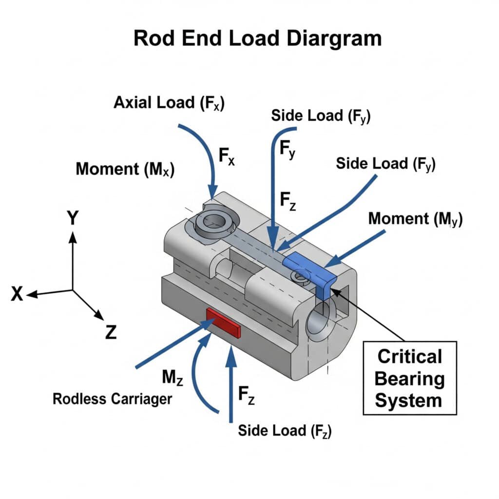
Understanding Load Types
When matching rod end loads, you need to consider three primary load types:
Axial Load
This is the force acting along the axis of the cylinder rod:
- Directly related to the cylinder’s bore size and operating pressure
- Most cylinders are designed primarily for axial loads
- For rodless cylinders, this is the primary working load
Side Load
This is force perpendicular to the cylinder axis:
- Can cause premature seal wear and rod bending
- Critical in rodless cylinder selection
- Often underestimated in applications
Moment Load
This is rotational force causing twisting:
- Can damage bearings and seals
- Particularly important in extended stroke applications
- Measured in Nm (Newton-meters)
Rod End Load Matching Table
Here’s a simplified reference table for matching common rodless cylinder sizes with appropriate load capacities:
| Cylinder Bore (mm) | Max Axial Load (N) | Max Side Load (N) | Max Moment Load (Nm) | Typische Anwendungen |
|---|---|---|---|---|
| 16 | 300 | 30 | 5 | Light assembly, small part transfer |
| 25 | 750 | 75 | 15 | Medium assembly, material handling |
| 32 | 1,200 | 120 | 25 | General automation, medium load transfer |
| 40 | 1,900 | 190 | 40 | Heavy material handling, moderate industrial use |
| 50 | 3,000 | 300 | 60 | Heavy industrial applications |
| 63 | 4,800 | 480 | 95 | Very heavy load handling |
Bearing System Considerations
For rodless cylinders specifically, the bearing system determines load capacity:
Ball bearing systems5
– Higher load capacity
– Lower friction
– Better for high-speed applications
– More expensiveSlide bearing systems
– More economical
– Better for dirty environments
– Generally lower load capacity
– Higher frictionRoller bearing systems
– Highest load capacity
– Suitable for heavy-duty applications
– Excellent for long strokes
– Require precise alignment
I recently helped a manufacturing plant in the UK replace their premium brand rodless cylinders with our Bepto equivalents. By properly matching the bearing system to their application needs, they not only solved their immediate downtime problem but also extended the maintenance interval by 30%.
When Should You Use Anti-rotation Pneumatic Cylinders in Your System?
Anti-rotation cylinders prevent unwanted rotation of the piston rod during operation, ensuring precise linear motion in specific applications.
Anti-rotation pneumatic cylinders should be used when your application requires precise linear movement without any rotational deviation, when handling non-symmetrical loads, or when the cylinder must resist external rotational forces that could compromise positioning accuracy.

Common Anti-rotation Mechanisms
There are several methods used to prevent rotation in pneumatic cylinders:
Guide Rod Systems
- Additional rods parallel to the main piston rod
- Provides excellent stability and precision
- Higher cost but very reliable
- Common in precision manufacturing applications
Profile Rod Design
- Non-circular rod cross-section prevents rotation
- Compact design without external components
- Good for space-constrained applications
- May have lower load capacity
External Guide Systems
- Separate guide mechanisms working alongside the cylinder
- Highest precision and load capacity
- More complex installation
- Used in high-precision automation
Application Scenarios Analysis
Here are the key application scenarios where anti-rotation cylinders are essential:
1. Asymmetrical Load Handling
When the load’s center of gravity is offset from the cylinder axis, standard cylinders may rotate under pressure. Anti-rotation cylinders are critical for:
- Robotic grippers handling irregular objects
- Assembly machines with offset tooling
- Material handling with unbalanced loads
2. Precision Positioning Applications
Applications requiring exact positioning benefit from anti-rotation features:
- CNC machine tool components
- Automated testing equipment
- Precision assembly operations
- Medical device manufacturing
3. Resistance to External Torque
When external forces might cause rotation:
- Machining operations with cutting forces
- Pressing applications with potential misalignment
- Applications with side-acting forces
Case Study: Anti-rotation Solution
A customer in Sweden was experiencing alignment issues in their packaging equipment. Their standard rodless cylinders were rotating slightly under load, causing misalignment and product damage.
We recommended our Bepto anti-rotation rodless cylinders with dual bearing rails. The results were immediate:
- Eliminated rotation issues completely
- Reduced product damage by 95%
- Increased production speed by 15%
- Reduced maintenance frequency
Selection Criteria Table
| Application Requirement | Standard-Zylinder | Guide Rod Anti-rotation | Profile Rod Anti-rotation | External Guide System |
|---|---|---|---|---|
| Precision level needed | Niedrig | Mittel-Hoch | Mittel | Sehr hoch |
| Load symmetry | Symmetrical | Can handle asymmetry | Moderate asymmetry | High asymmetry |
| External torque present | Minimal | Moderate resistance | Low-moderate resistance | High resistance |
| Platzbeschränkungen | Minimal | Requires more space | Compact | Requires most space |
| Cost considerations | Lowest | Mittel | Medium-high | Höchste |
Schlussfolgerung
Selecting the right pneumatic actuator requires understanding force calculations, matching rod end load specifications, and analyzing application needs for special features like anti-rotation. By following these guidelines, you can ensure optimal performance, reduce downtime, and extend the life of your pneumatic systems.
FAQs About Pneumatic Actuator Selection
What is the difference between a rodless cylinder and a standard pneumatic cylinder?
A rodless cylinder contains the piston movement within its body without an extending rod, saving space and allowing longer strokes in compact areas. Standard cylinders have an extending rod that moves outward during operation, requiring additional clearance space.
How do I calculate the required bore size for my pneumatic cylinder?
Calculate the required force for your application, then use the formula: Bore diameter = √(4F/πP), where F is the required force in Newtons and P is the available pressure in Pascals. Always add a safety factor of 25-30% to account for friction and inefficiencies.
Can rodless pneumatic cylinders handle the same loads as conventional cylinders?
Rodless pneumatic cylinders typically have lower side load capacities than conventional cylinders of the same bore size. However, they excel in applications requiring long strokes in limited spaces and often feature better integrated bearing systems for supporting loads.
Wie funktioniert ein kolbenstangenloser Luftzylinder?
Rodless air cylinders work by using a sealed carriage that moves along the cylinder body. As compressed air enters one chamber, it pushes the internal piston, which is connected to an external carriage through a slot sealed by special bands or magnetic coupling, creating linear motion without an extending rod.
Was sind die Hauptanwendungen für kolbenstangenlose Zylinder?
Rodless cylinders are ideal for long-stroke applications in limited spaces, material handling systems, automation equipment, packaging machinery, door operators, and any application where space constraints make conventional cylinders impractical.
How can I extend the life of my pneumatic actuators?
Extend pneumatic actuator life by ensuring proper installation with correct alignment, using clean and dry compressed air with appropriate lubrication, staying within the manufacturer’s specified load limits, and performing regular maintenance including seal inspection and replacement.
-
Provides a foundational explanation of pressure as a measure of force applied perpendicular to the surface of an object per unit area, which is the principle behind the F=PxA formula. ↩
-
Describes the different designs of rodless cylinders, such as magnetically coupled and mechanically coupled (band) types, and explains their respective advantages and operating principles. ↩
-
Explains the various sources of friction in a pneumatic cylinder, including seal friction and bearing friction, and how these forces reduce the actual force output compared to theoretical calculations. ↩
-
Offers an overview of the different types of static loads in mechanical engineering, including axial (tension/compression), shear (side), and moment (bending/twisting) forces. ↩
-
Provides a comparison of the fundamental types of bearings, detailing their differences in load capacity, friction characteristics, speed ratings, and suitability for various applications. ↩
