AI Search

Search this site

Integrated pneumatic control

Fieldbus and multi-pin control for pneumatic valves.

A valve island brings electrical control and air distribution together at the machine. Modular manifolds, plug-in controllers and matching cables connect multiple solenoid valves through one coordinated assembly.

EtherCATCANopenPROFINETIO-Link
F / R / MValve island systems
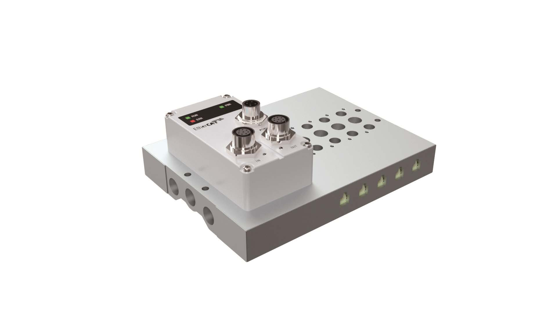
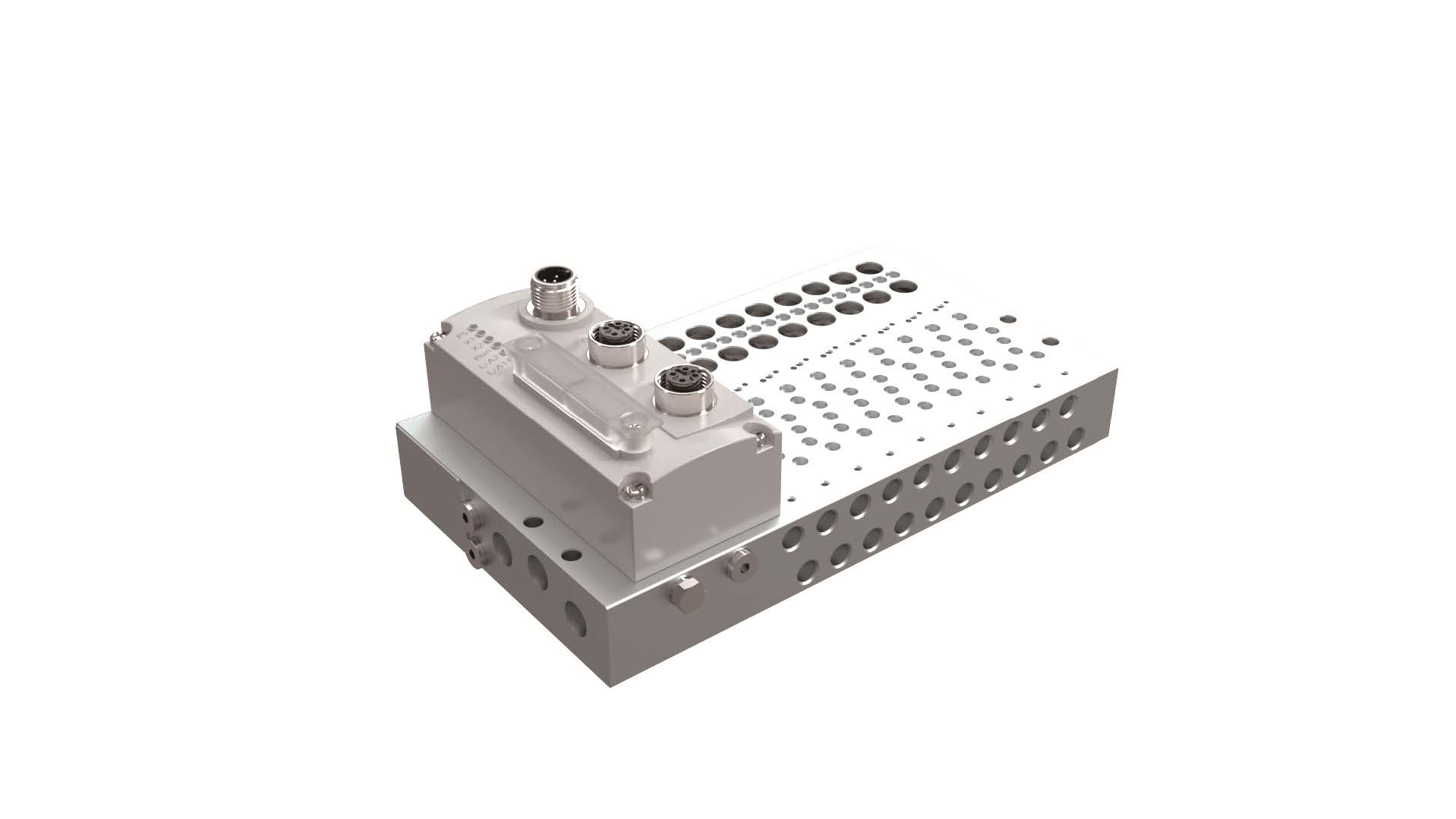
Fieldbus manifold with plug-in controller and multiple valve mounting stations
Controller + manifold + valve stationsShown without solenoid valves.

System overview

Control, power and compressed-air connections

The controller receives machine commands; the manifold groups the valve connections and pneumatic passages. Solenoid valves then distribute compressed air to the actuators.

Communication24 V powerCompressed air
Pneumatic valve island system layoutCommunication and power connect the machine controller to the valve island. Prepared compressed air flows through the manifold and valves to the machine actuators. Select a numbered component for details.1
Machine controller
PLC
2
24 V power supply
24 V
3
Plug-in control box
4
Manifold and solenoid valves
5
Machine actuators
6
Prepared compressed-air supply
SR
Pneumatic valve island system layoutCommunication and power connect the machine controller to the valve island. Prepared compressed air flows through the manifold and valves to the machine actuators. Select a numbered component for details.1
Machine controller
PLC
2
24 V power supply
24 V
3
Plug-in control box
4
Manifold and solenoid valves
5
Machine actuators
6
Prepared compressed-air supply
SR
A valve island connects the machine controller, 24 V power supply and compressed-air circuit to the pneumatic actuators.

Machine controller

The PLC or IO-Link master sends commands through the selected communication protocol. EtherCAT, CANopen, PROFINET and IO-Link require the corresponding control-box version.

Compare control architectures

24 V power supply

The controller and solenoid coils use a 24 V supply. The power connection is separate from the communication link; connector assignments are shown in the wiring diagrams.

View power and wiring details

Plug-in control box

An FR box connects to an R manifold; an FF box connects to an F manifold. The box receives machine commands and switches the valve outputs. M manifolds use direct multi-pin wiring instead.

View controllers and cables

Manifold and solenoid valves

The manifold combines valve mounting positions with internal air passages. Valve interfaces are available for the 3V, 4V, 7V, SY and VUVG families.

View compatible valve families

Machine actuators

The valve outlets connect to cylinders, grippers and other pneumatic actuators. Supply and exhaust switching produces the required motion at the machine.

Explore valve interfaces

Prepared compressed-air supply

Filtered and regulated compressed air enters the manifold through a common supply port. The valves distribute the air to cylinders, grippers and other machine actuators.

View manifold connections

System architecture

F, R and M connection architectures

F and R manifolds use plug-in control boxes. M manifolds collect valve signals through a multi-pin connector. Each architecture has its own valve interface and station range.

R · Fieldbus

A fieldbus interface for common valve families

The R manifold pairs with an FR control box and supports 3V, 4V, 7V and SY valve families. EtherCAT, CANopen, PROFINET and IO-Link controller options connect the assembly to the machine control system.

Compatible valves
3V / 4V / 7V / SY
Controller / connection
FR
Valve stations
4–24
Coil voltage
24 V

SY configurations support up to 24 double-solenoid valves / 48 coils. Controller capacity and valve wiring must match the assembly.
R · Fieldbus

EtherCAT / CANopen / PROFINET / IO-Link
F · Fieldbus

A dedicated interface for VUVG valves

F manifolds pair with FF control boxes and accommodate VUVG B10, B14 and B18 single- and double-solenoid valves. The plug-in controller links the valve assembly to the machine network.

Compatible valves
VUVG B10 / B14 / B18
Controller / connection
FF
Valve stations
4–24
Coil voltage
24 V

B10F, B14F and B18F identify the manifold valve interfaces. The manifold and controller must match the required valve count.

F · Fieldbus

EtherCAT / CANopen / PROFINET / IO-Link
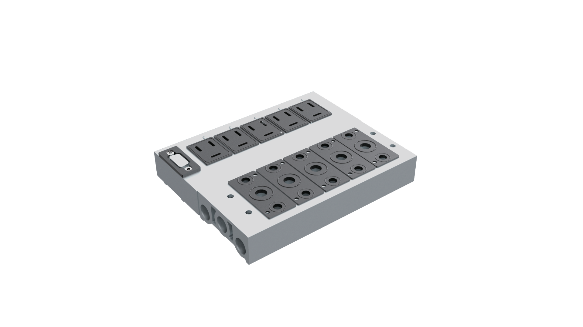
M · Multi-pin

Grouped valve wiring for conventional I/O

M manifolds consolidate individual solenoid signals in a multi-pin connection. Matching SM cables link the valve assembly to the control cabinet without a fieldbus control box on the manifold.

Compatible valves
3V / 4V / 7V / SY
Controller / connection
DB15 / DB25
Valve stations
4–14
Coil voltage
24 V

The connector pin assignment depends on the valve and coil arrangement. Use the matching DB15 or DB25 wiring table.

M · Multi-pin

Multi-pin I/O

Valve compatibility

Valve interfaces for 3V, 4V, 7V, SY and VUVG

R and M manifolds support 3V, 4V, 7V and SY valve families. F manifolds use VUVG B10, B14 and B18 interfaces.

System components

Control boxes, cables and extension modules

FF / FR

Plug-in control boxes

FF boxes pair with F manifolds; FR boxes pair with R manifolds. Communication protocol, connector and output capacity are defined in the control-box model code.

View technical details

SR

Power and communication cables

Straight and angled M12 options, RJ45 connections, cascade cables and CANopen termination components serve the control-box connections.

View technical details

SM

Multi-pin control cables

DB15, DB25 and dual-DB15 connections carry grouped valve signals. Standard and drag-chain cable versions are available in standard and custom lengths.

View technical details

4V130-PLUG / 4V230-PLUG

Double-solenoid extension modules

Dedicated modules extend the electrical connection for double-solenoid valves in the 4V100 and 4V200 families.

View technical details

Technical library

Manifold specifications, dimensions and wiring

Ordering codes, valve station ranges, mounting dimensions and connector pin assignments for manifolds, control boxes and cables.

014V110 Valve Manifolds

R-4V110 fieldbus and M-4V110 multipin manifolds bring the electrical connections and air passages for 4V110 valves into one base.

Compatible valve
4V110
Coil voltage
24 V DC
R valve positions
4–24
M valve positions
4–14
Thread options
G / PT

Ordering code

R — 4V110 — W4 — G

Series

R: fieldbus manifold

Compatible valve

4V110

Valve positions

W4–W24

Thread suffix

G: G thread

Blank: PT thread

4V110 configurations

PropertyR seriesM series
Compatible valve4V1104V110
Valve positions4–244–14
Coil voltage24 V DC24 V DC
Electrical connectionFR control boxDB15
Thread optionsG / PTG / PT

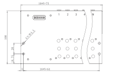
R-4V110 dimensions

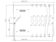
R-4V110 manifold dimensions
R-4V110 manifold dimensionsOpen full-size drawing ↗
DimensionValue (mm)
Overall length19 × N + 75
Mounting-hole horizontal span19 × N + 64
Base width100
Mounting holes4 × Ø4.5
Mounting-hole row spacing20
Lower mounting-hole row offset18.75
Left mounting-hole offset5
Overall length at N = 8227
Mounting-hole span at N = 8216

N is the number of valve positions. Dimensions are in millimetres.

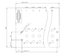
M-4V110 dimensions

M-4V110 manifold dimensions
M-4V110 manifold dimensionsOpen full-size drawing ↗
DimensionValue (mm)
Overall length19 × N + 30
Mounting-hole horizontal span19 × N + 9
Base width100
Mounting holes4 × Ø4.5
Mounting-hole row spacing20
Lower mounting-hole row offset18.75
Left mounting-hole offset15
Overall length at N = 8182
Mounting-hole span at N = 8161

N is the number of valve positions. Dimensions are in millimetres.

4V110 ordering code

Code fieldR seriesM series
SeriesRM
Compatible valve4V1104V110
Valve positionsW4–W24W4–W14
ConnectorFR control boxBlank: DB15 female; DB15G: DB15 male
Thread suffixG: G thread; blank: PT threadG: G thread; blank: PT thread
ExampleR-4V110-W8M-4V110-W14

4V110 assembly examples

ComponentEtherCAT: 8 positions, 2 mCANopen: 16 positions, 6 mMultipin: 14 positions, 2 mDB25: 18 positions, 6 m
ManifoldR-4V110-W8R-4V110-W16M-4V110-W14R-4V110-W18
Control boxFR-EC-M12-W10FR-CAN-M12-W16—FR-DB-25-W24
Power cableSR-M12-DC-2.0SR-M12-DC-6.0——
Communication cableSR-M12-RJ45-2.0SR-M12-E0310-6.0SM-DB15-2.0SM-DB25-6.0
Terminator—SR-M12-T02——
024V210 Valve Manifolds

R-4V210 fieldbus and M-4V210 multipin manifolds bring the electrical connections and air passages for 4V210 valves into one base.

Compatible valve
4V210
Coil voltage
24 V DC
R valve positions
4–24
M valve positions
4–14
Thread options
G / PT

Ordering code

R — 4V210 — W4 — G

Series

R: fieldbus manifold

Compatible valve

4V210

Valve positions

W4–W24

Thread suffix

G: G thread

Blank: PT thread

4V210 configurations

PropertyR seriesM series
Compatible valve4V2104V210
Valve positions4–244–14
Coil voltage24 V DC24 V DC
Electrical connectionFR control boxDB15
Thread optionsG / PTG / PT

R-4V210 dimensions

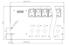
R-4V210 manifold dimensions
R-4V210 manifold dimensionsOpen full-size drawing ↗
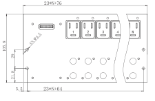
DimensionValue (mm)
Overall length23 × N + 76
Mounting-hole horizontal span23 × N + 64
Base width118
Mounting holes4 × Ø4.5
Mounting-hole row spacing21
Lower mounting-hole row offset19.5
Left mounting-hole offset5.5
Overall length at N = 8260
Mounting-hole span at N = 8248

N is the number of valve positions. Dimensions are in millimetres.

M-4V210 dimensions

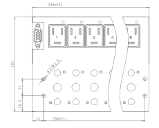
M-4V210 manifold dimensions
M-4V210 manifold dimensionsOpen full-size drawing ↗
DimensionValue (mm)
Overall length23 × N + 31
Mounting-hole horizontal span23 × N + 11
Base width118
Mounting holes4 × Ø4.5
Mounting-hole row spacing21
Lower mounting-hole row offset19.5
Left mounting-hole offset14
Overall length at N = 8215
Mounting-hole span at N = 8195

N is the number of valve positions. Dimensions are in millimetres.

4V210 ordering code

Code fieldR seriesM series
SeriesRM
Compatible valve4V2104V210
Valve positionsW4–W24W4–W14
ConnectorFR control boxBlank: DB15 female; DB15G: DB15 male
Thread suffixG: G thread; blank: PT threadG: G thread; blank: PT thread
ExampleR-4V210-W8M-4V210-W14

4V210 assembly examples

ComponentEtherCAT: 8 positions, 2 mCANopen: 16 positions, 6 mMultipin: 14 positions, 2 mDB25: 18 positions, 6 m
ManifoldR-4V210-W8R-4V210-W16M-4V210-W14R-4V210-W18
Control boxFR-EC-M12-W10FR-CAN-M12-W16—FR-DB-25-W24
Power cableSR-M12-DC-2.0SR-M12-DC-6.0——
Communication cableSR-M12-RJ45-2.0SR-M12-E0310-6.0SM-DB15-2.0SM-DB25-6.0
Terminator—SR-M12-T02——
034V310 Valve Manifolds

R-4V310 fieldbus and M-4V310 multipin manifolds bring the electrical connections and air passages for 4V310 valves into one base.

Compatible valve
4V310
Coil voltage
24 V DC
R valve positions
4–24
M valve positions
4–14
Thread options
G / PT

Ordering code

R — 4V310 — W4 — G

Series

R: fieldbus manifold

Compatible valve

4V310

Valve positions

W4–W24

Thread suffix

G: G thread

Blank: PT thread

4V310 configurations

PropertyR seriesM series
Compatible valve4V3104V310
Valve positions4–244–14
Coil voltage24 V DC24 V DC
Electrical connectionFR control boxDB15
Thread optionsG / PTG / PT

R-4V310 dimensions

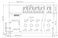
R-4V310 manifold dimensions
R-4V310 manifold dimensionsOpen full-size drawing ↗
DimensionValue (mm)
Overall length28 × N + 76.5
Mounting-hole horizontal span28 × N + 65.5
Base width135.5
Mounting holes4 × Ø4.5
Mounting-hole row spacing26
Lower mounting-hole row offset18
Overall length at N = 8300.5
Other marked dimensions38.95 / 96.55 / 83.00 / 3.30 / 6.50 / 5.00
Other marked holesØ3.24 / 4 × Ø2.50

N is the number of valve positions. Dimensions are in millimetres.

Confirm the mounting-hole horizontal span before machining this configuration.

M-4V310 dimensions

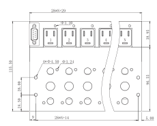
M-4V310 manifold dimensions
M-4V310 manifold dimensionsOpen full-size drawing ↗
DimensionValue (mm)
Overall length28 × N + 29
Mounting-hole horizontal span28 × N + 14
Base width135.5
Mounting holes4 × Ø4.5
Mounting-hole row spacing26
Lower mounting-hole row offset24.5
Left mounting-hole offset9
Overall length at N = 8253
Mounting-hole span at N = 8238
Other marked dimensions38.95 / 96.55 / 5.00
Other marked holesØ3.24 / Ø3.30

N is the number of valve positions. Dimensions are in millimetres.

4V310 ordering code

Code fieldR seriesM series
SeriesRM
Compatible valve4V3104V310
Valve positionsW4–W24W4–W14
ConnectorFR control boxBlank: DB15 female; DB15G: DB15 male
Thread suffixG: G thread; blank: PT threadG: G thread; blank: PT thread
ExampleR-4V310-W8M-4V310-W14

4V310 assembly examples

ComponentEtherCAT: 8 positions, 2 mCANopen: 16 positions, 6 mMultipin: 14 positions, 2 mDB25: 18 positions, 6 m
ManifoldR-4V310-W8R-4V310-W16M-4V310-W14R-4V310-W18
Control boxFR-EC-M12-W10FR-CAN-M12-W16—FR-DB-25-W24
Power cableSR-M12-DC-2.0SR-M12-DC-6.0——
Communication cableSR-M12-RJ45-2.0SR-M12-E0310-6.0SM-DB15-2.0SM-DB25-6.0
Terminator—SR-M12-T02——
043V110 Valve Manifolds

R-3V110 fieldbus and M-3V110 multipin manifolds bring the electrical connections and air passages for 3V110 valves into one base.

Compatible valve
3V110
Coil voltage
24 V DC
R valve positions
4–24
M valve positions
4–14
Thread options
G / PT

Ordering code

R — 3V110 — W4 — G

Series

R: fieldbus manifold

Compatible valve

3V110

Valve positions

W4–W24

Thread suffix

G: G thread

Blank: PT thread

3V110 configurations

PropertyR seriesM series
Compatible valve3V1103V110
Valve positions4–244–14
Coil voltage24 V DC24 V DC
Electrical connectionFR control boxDB15
Thread optionsG / PTG / PT

R-3V110 dimensions

R-3V110 manifold dimensions
R-3V110 manifold dimensionsOpen full-size drawing ↗
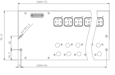
DimensionValue (mm)
Overall length19 × N + 75
Mounting-hole horizontal span19 × N + 64
Base width91.6
Mounting holes4 × Ø4.5
Mounting-hole row spacing25
Lower mounting-hole row offset19.5
Left mounting-hole offset5
Overall length at N = 8227
Mounting-hole span at N = 8216

N is the number of valve positions. Dimensions are in millimetres.

M-3V110 dimensions

M-3V110 manifold dimensions
M-3V110 manifold dimensionsOpen full-size drawing ↗
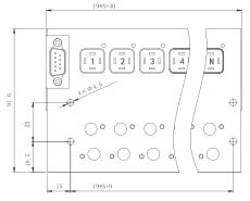
DimensionValue (mm)
Overall length19 × N + 30
Mounting-hole horizontal span19 × N + 9
Base width91.6
Mounting holes4 × Ø4.5
Mounting-hole row spacing25
Lower mounting-hole row offset19.5
Left mounting-hole offset15
Overall length at N = 8182
Mounting-hole span at N = 8161

N is the number of valve positions. Dimensions are in millimetres.

3V110 ordering code

Code fieldR seriesM series
SeriesRM
Compatible valve3V1103V110
Valve positionsW4–W24W4–W14
ConnectorFR control boxBlank: DB15 female; DB15G: DB15 male
Thread suffixG: G thread; blank: PT threadG: G thread; blank: PT thread
ExampleR-3V110-W8M-3V110-W14

3V110 assembly examples

ComponentEtherCAT: 8 positions, 2 mCANopen: 16 positions, 6 mMultipin: 14 positions, 2 mDB25: 18 positions, 6 m
ManifoldR-3V110-W8R-3V110-W16M-3V110-W14R-3V110-W18
Control boxFR-EC-M12-W10FR-CAN-M12-W16—FR-DB-25-W24
Power cableSR-M12-DC-2.0SR-M12-DC-6.0——
Communication cableSR-M12-RJ45-2.0SR-M12-E0310-6.0SM-DB15-2.0SM-DB25-6.0
Terminator—SR-M12-T02——
053V210 Valve Manifolds

R-3V210 fieldbus and M-3V210 multipin manifolds bring the electrical connections and air passages for 3V210 valves into one base.

Compatible valve
3V210
Coil voltage
24 V DC
R valve positions
4–24
M valve positions
4–14
Thread options
G / PT

Ordering code

R — 3V210 — W4 — G

Series

R: fieldbus manifold

Compatible valve

3V210

Valve positions

W4–W24

Thread suffix

G: G thread

Blank: PT thread

3V210 configurations

PropertyR seriesM series
Compatible valve3V2103V210
Valve positions4–244–14
Coil voltage24 V DC24 V DC
Electrical connectionFR control boxDB15
Thread optionsG / PTG / PT

R-3V210 dimensions

R-3V210 manifold dimensions
R-3V210 manifold dimensionsOpen full-size drawing ↗
DimensionValue (mm)
Overall length23 × N + 76
Mounting-hole horizontal span23 × N + 64
Base width105.8
Mounting holes4 × Ø4.5
Mounting-hole row spacing29
Lower mounting-hole row offset21.8
Left mounting-hole offset5.5
Overall length at N = 8260
Mounting-hole span at N = 8248

N is the number of valve positions. Dimensions are in millimetres.

M-3V210 dimensions

M-3V210 manifold dimensions
M-3V210 manifold dimensionsOpen full-size drawing ↗
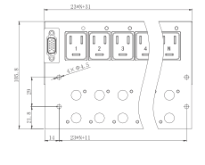
DimensionValue (mm)
Overall length23 × N + 31
Mounting-hole horizontal span23 × N + 11
Base width105.8
Mounting holes4 × Ø4.5
Mounting-hole row spacing29
Lower mounting-hole row offset21.8
Left mounting-hole offset14
Overall length at N = 8215
Mounting-hole span at N = 8195

N is the number of valve positions. Dimensions are in millimetres.

3V210 ordering code

Code fieldR seriesM series
SeriesRM
Compatible valve3V2103V210
Valve positionsW4–W24W4–W14
ConnectorFR control boxBlank: DB15 female; DB15G: DB15 male
Thread suffixG: G thread; blank: PT threadG: G thread; blank: PT thread
ExampleR-3V210-W8M-3V210-W14

3V210 assembly examples

ComponentEtherCAT: 8 positions, 2 mCANopen: 16 positions, 6 mMultipin: 14 positions, 2 mDB25: 18 positions, 6 m
ManifoldR-3V210-W8R-3V210-W16M-3V210-W14R-3V210-W18
Control boxFR-EC-M12-W10FR-CAN-M12-W16—FR-DB-25-W24
Power cableSR-M12-DC-2.0SR-M12-DC-6.0——
Communication cableSR-M12-RJ45-2.0SR-M12-E0310-6.0SM-DB15-2.0SM-DB25-6.0
Terminator—SR-M12-T02——
067V110 Valve Manifolds

R-7V110 fieldbus and M-7V110 multipin manifolds bring the electrical connections and air passages for 7V110 valves into one base.

Compatible valve
7V110
Coil voltage
24 V DC
R valve positions
4–24
M valve positions
4–14
Thread options
G / PT

Ordering code

R — 7V110 — W4 — G

Series

R: fieldbus manifold

Compatible valve

7V110

Valve positions

W4–W24

Thread suffix

G: G thread

Blank: PT thread

7V110 configurations

PropertyR seriesM series
Compatible valve7V1107V110
Valve positions4–244–14
Coil voltage24 V DC24 V DC
Electrical connectionFR control boxDB15
Thread optionsG / PTG / PT

R-7V110 dimensions

R-7V110 manifold dimensions
R-7V110 manifold dimensionsOpen full-size drawing ↗
DimensionValue (mm)
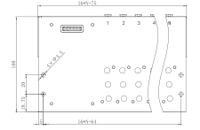
Overall length16 × N + 75
Mounting-hole horizontal span16 × N + 64
Base width100
Mounting holes4 × Ø4.5
Mounting-hole row spacing20
Lower mounting-hole row offset18.75
Left mounting-hole offset5
Overall length at N = 8203
Mounting-hole span at N = 8192

N is the number of valve positions. Dimensions are in millimetres.

M-7V110 dimensions

M-7V110 manifold dimensions
M-7V110 manifold dimensionsOpen full-size drawing ↗
DimensionValue (mm)
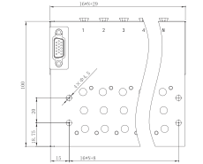
Overall length16 × N + 29
Mounting-hole horizontal span16 × N + 8
Base width100
Mounting holes4 × Ø4.5
Mounting-hole row spacing20
Lower mounting-hole row offset18.75
Left mounting-hole offset15
Overall length at N = 8157
Mounting-hole span at N = 8136

N is the number of valve positions. Dimensions are in millimetres.

7V110 ordering code

Code fieldR seriesM series
SeriesRM
Compatible valve7V1107V110
Valve positionsW4–W24W4–W14
ConnectorFR control boxBlank: DB15 female; DB15G: DB15 male
Thread suffixG: G thread; blank: PT threadG: G thread; blank: PT thread
ExampleR-7V110-W8M-7V110-W14

7V110 assembly examples

ComponentEtherCAT: 8 positions, 2 mCANopen: 16 positions, 6 mMultipin: 14 positions, 2 mDB25: 18 positions, 6 m
ManifoldR-7V110-W8R-7V110-W16M-7V110-W14R-7V110-W18
Control boxFR-EC-M12-W10FR-CAN-M12-W16—FR-DB-25-W24
Power cableSR-M12-DC-2.0SR-M12-DC-6.0——
Communication cableSR-M12-RJ45-2.0SR-M12-E0310-6.0SM-DB15-2.0SM-DB25-6.0
Terminator—SR-M12-T02——
077V210 Valve Manifolds

R-7V210 fieldbus and M-7V210 multipin manifolds bring the electrical connections and air passages for 7V210 valves into one base.

Compatible valve
7V210
Coil voltage
24 V DC
R valve positions
4–24
M valve positions
4–14
Thread options
G / PT

Ordering code

R — 7V210 — W4 — G

Series

R: fieldbus manifold

Compatible valve

7V210

Valve positions

W4–W24

Thread suffix

G: G thread

Blank: PT thread

7V210 configurations

PropertyR seriesM series
Compatible valve7V2107V210
Valve positions4–244–14
Coil voltage24 V DC24 V DC
Electrical connectionFR control boxDB15
Thread optionsG / PTG / PT

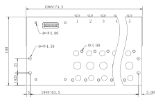
R-7V210 dimensions

R-7V210 manifold dimensions
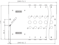
R-7V210 manifold dimensionsOpen full-size drawing ↗
DimensionValue (mm)
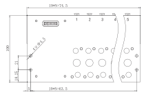
Overall length19 × N + 74.5
Mounting-hole horizontal span19 × N + 63.5
Base width100
Mounting holes4 × Ø4.5
Mounting-hole row spacing21
Lower mounting-hole row offset18.25
Left mounting-hole offset5
Overall length at N = 8226.5
Mounting-hole span at N = 8215.5
Other marked dimensions5.00
Other marked holesØ3.00 / 4 × Ø3.00

N is the number of valve positions. Dimensions are in millimetres.

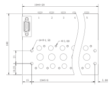
M-7V210 dimensions

M-7V210 manifold dimensions
M-7V210 manifold dimensionsOpen full-size drawing ↗
DimensionValue (mm)
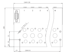
Overall length19 × N + 29
Mounting-hole horizontal span19 × N + 8
Base width100
Mounting holes4 × Ø4.5
Mounting-hole row spacing21
Lower mounting-hole row offset18.25
Left mounting-hole offset15
Overall length at N = 8181
Mounting-hole span at N = 8160
Other marked dimensions5.00
Other marked holesØ3.00

N is the number of valve positions. Dimensions are in millimetres.

7V210 ordering code

Code fieldR seriesM series
SeriesRM
Compatible valve7V2107V210
Valve positionsW4–W24W4–W14
ConnectorFR control boxBlank: DB15 female; DB15G: DB15 male
Thread suffixG: G thread; blank: PT threadG: G thread; blank: PT thread
ExampleR-7V210-W8M-7V210-W14

7V210 assembly examples

ComponentEtherCAT: 8 positions, 2 mCANopen: 16 positions, 6 mMultipin: 14 positions, 2 mDB25: 18 positions, 6 m
ManifoldR-7V210-W8R-7V210-W16M-7V210-W14R-7V210-W18
Control boxFR-EC-M12-W10FR-CAN-M12-W16—FR-DB-25-W24
Power cableSR-M12-DC-2.0SR-M12-DC-6.0——
Communication cableSR-M12-RJ45-2.0SR-M12-E0310-6.0SM-DB15-2.0SM-DB25-6.0
Terminator—SR-M12-T02——
08SY5120 Valve Manifolds

R-SY5120 fieldbus and M-SY5120 multipin manifolds bring the electrical connections and air passages for SY5120 valves into one base.

Compatible valve
SY5120
Coil voltage
24 V DC
R valve positions
4–24
M valve positions
4–14
Thread options
G / PT

Ordering code

R — SY5120 — W4 — G

Series

R: fieldbus manifold

Compatible valve

SY5120

Valve positions

W4–W24

Thread suffix

G: G thread

Blank: PT thread

SY5120 configurations

PropertyR seriesM series
Compatible valveSY5120SY5120
Valve positions4–244–14
Coil voltage24 V DC24 V DC
Electrical connectionFR control boxDB15
Thread optionsG / PTG / PT

R-SY5120 dimensions

R-SY5120 manifold dimensions
R-SY5120 manifold dimensionsOpen full-size drawing ↗
DimensionValue (mm)
Overall length16 × N + 75
Mounting-hole horizontal span16 × N + 64
Base width100
Mounting holes4 × Ø4.5
Mounting-hole row spacing20
Lower mounting-hole row offset18.75
Left mounting-hole offset5
Overall length at N = 8203
Mounting-hole span at N = 8192

N is the number of valve positions. Dimensions are in millimetres.

M-SY5120 dimensions

M-SY5120 manifold dimensions
M-SY5120 manifold dimensionsOpen full-size drawing ↗
DimensionValue (mm)
Overall length16 × N + 29
Mounting-hole horizontal span16 × N + 8
Base width100
Mounting holes4 × Ø4.5
Mounting-hole row spacing20
Lower mounting-hole row offset18.75
Left mounting-hole offset15
Overall length at N = 8157
Mounting-hole span at N = 8136

N is the number of valve positions. Dimensions are in millimetres.

SY5120 ordering code

Code fieldR seriesM series
SeriesRM
Compatible valveSY5120SY5120
Valve positionsW4–W24W4–W14
ConnectorFR control boxBlank: DB15 female; DB15G: DB15 male
Thread suffixG: G thread; blank: PT threadG: G thread; blank: PT thread
ExampleR-SY5120-W8M-SY5120-W14

SY5120 assembly examples

ComponentEtherCAT: 8 positions, 2 mCANopen: 16 positions, 6 mMultipin: 14 positions, 2 mDB25: 18 positions, 6 m
ManifoldR-SY5120-W8R-SY5120-W16M-SY5120-W14R-SY5120-W18
Control boxFR-EC-M12-W10FR-CAN-M12-W16—FR-DB-25-W24
Power cableSR-M12-DC-2.0SR-M12-DC-6.0——
Communication cableSR-M12-RJ45-2.0SR-M12-E0310-6.0SM-DB15-2.0SM-DB25-6.0
Terminator—SR-M12-T02——
09SY7120 Valve Manifolds

R-SY7120 fieldbus and M-SY7120 multipin manifolds bring the electrical connections and air passages for SY7120 valves into one base.

Compatible valve
SY7120
Coil voltage
24 V DC
R valve positions
4–24
M valve positions
4–14
Thread options
G / PT

Ordering code

R — SY7120 — W4 — G

Series

R: fieldbus manifold

Compatible valve

SY7120

Valve positions

W4–W24

Thread suffix

G: G thread

Blank: PT thread

SY7120 configurations

PropertyR seriesM series
Compatible valveSY7120SY7120
Valve positions4–244–14
Coil voltage24 V DC24 V DC
Electrical connectionFR control boxDB15
Thread optionsG / PTG / PT

R-SY7120 dimensions

R-SY7120 manifold dimensions
R-SY7120 manifold dimensionsOpen full-size drawing ↗
DimensionValue (mm)
Overall length19 × N + 74.5
Mounting-hole horizontal span19 × N + 63.5
Base width100
Mounting holes4 × Ø4.5
Mounting-hole row spacing21
Lower mounting-hole row offset18.25
Left mounting-hole offset5
Overall length at N = 8226.5
Mounting-hole span at N = 8215.5

N is the number of valve positions. Dimensions are in millimetres.

M-SY7120 dimensions

M-SY7120 manifold dimensions
M-SY7120 manifold dimensionsOpen full-size drawing ↗
DimensionValue (mm)
Overall length19 × N + 29
Mounting-hole horizontal span19 × N + 8
Base width100
Mounting holes4 × Ø4.5
Mounting-hole row spacing21
Lower mounting-hole row offset18.25
Left mounting-hole offset15
Overall length at N = 8181
Mounting-hole span at N = 8160

N is the number of valve positions. Dimensions are in millimetres.

SY7120 ordering code

Code fieldR seriesM series
SeriesRM
Compatible valveSY7120SY7120
Valve positionsW4–W24W4–W14
ConnectorFR control boxBlank: DB15 female; DB15G: DB15 male
Thread suffixG: G thread; blank: PT threadG: G thread; blank: PT thread
ExampleR-SY7120-W8M-SY7120-W14

SY7120 assembly examples

ComponentEtherCAT: 8 positions, 2 mCANopen: 16 positions, 6 mMultipin: 14 positions, 2 mDB25: 18 positions, 6 m
ManifoldR-SY7120-W8R-SY7120-W16M-SY7120-W14R-SY7120-W18
Control boxFR-EC-M12-W10FR-CAN-M12-W16—FR-DB-25-W24
Power cableSR-M12-DC-2.0SR-M12-DC-6.0——
Communication cableSR-M12-RJ45-2.0SR-M12-E0310-6.0SM-DB15-2.0SM-DB25-6.0
Terminator—SR-M12-T02——
10SY5220 Valve Manifolds

R-SY5220 manifolds provide two coil connections per valve position for SY5220 double-solenoid valves, with an FR control box for the chosen control interface.

Compatible valve
SY5220
Coil voltage
24 V DC
R valve positions
4–24
Thread options
G / PT

Ordering code

R — SY5220 — W4 — G

Series

R: fieldbus manifold

Compatible valve

SY5220

Valve positions

W4–W24

Thread suffix

G: G thread

Blank: PT thread

SY5220 configurations

PropertyR series
Compatible valveSY5220
Valve positions4–24
Coil voltage24 V DC
Electrical connectionFR control box
Thread optionsG / PT

R-SY5220 dimensions

R-SY5220 manifold dimensions
R-SY5220 manifold dimensionsOpen full-size drawing ↗
DimensionValue (mm)
Overall length16 × N + 75
Mounting-hole horizontal span16 × N + 64
Base width118
Mounting holes4 × Ø4.5
Mounting-hole row spacing20
Lower mounting-hole row offset49
Left mounting-hole offset5
Overall length at N = 8203
Mounting-hole span at N = 8192

N is the number of valve positions. Dimensions are in millimetres.

SY5220 ordering code

Code fieldR series
SeriesR
Compatible valveSY5220
Valve positionsW4–W24
ConnectorFR control box
Thread suffixG: G thread; blank: PT thread
ExampleR-SY5220-W8

SY5220 assembly examples

ComponentEtherCAT: 8 positions, 2 mCANopen: 16 positions, 6 m
ManifoldR-SY5220-W8R-SY5220-W16
Control boxFR-EC-M12-W10FR-CAN-M12-W16
Power cableSR-M12-DC-2.0SR-M12-DC-6.0
Communication cableSR-M12-RJ45-2.0SR-M12-E0310-6.0
Terminator—SR-M12-T02
11SY7220 Valve Manifolds

R-SY7220 manifolds provide two coil connections per valve position for SY7220 double-solenoid valves, with an FR control box for the chosen control interface.

Compatible valve
SY7220
Coil voltage
24 V DC
R valve positions
4–24
Thread options
G / PT

Ordering code

R — SY7220 — W4 — G

Series

R: fieldbus manifold

Compatible valve

SY7220

Valve positions

W4–W24

Thread suffix

G: G thread

Blank: PT thread

SY7220 configurations

PropertyR series
Compatible valveSY7220
Valve positions4–24
Coil voltage24 V DC
Electrical connectionFR control box
Thread optionsG / PT

R-SY7220 dimensions

R-SY7220 manifold dimensions
R-SY7220 manifold dimensionsOpen full-size drawing ↗
DimensionValue (mm)
Overall length19 × N + 74.5
Mounting-hole horizontal span19 × N + 63.5
Base width118
Mounting holes4 × Ø4.5
Mounting-hole row spacing21
Lower mounting-hole row offset48.5
Left mounting-hole offset5
Overall length at N = 8226.5
Mounting-hole span at N = 8215.5

N is the number of valve positions. Dimensions are in millimetres.

SY7220 ordering code

Code fieldR series
SeriesR
Compatible valveSY7220
Valve positionsW4–W24
ConnectorFR control box
Thread suffixG: G thread; blank: PT thread
ExampleR-SY7220-W8

SY7220 assembly examples

ComponentEtherCAT: 8 positions, 2 mCANopen: 16 positions, 6 m
ManifoldR-SY7220-W8R-SY7220-W16
Control boxFR-EC-M12-W10FR-CAN-M12-W16
Power cableSR-M12-DC-2.0SR-M12-DC-6.0
Communication cableSR-M12-RJ45-2.0SR-M12-E0310-6.0
Terminator—SR-M12-T02
12F Series Compatible Valve Manifolds

F-series bases accept an FF control box and provide a common connection platform for compatible VUVG B10, B14 and B18 solenoid valves.

Compatible valves
VUVG B10 / B14 / B18
Coil voltage
24 V DC
Valve positions
4–24
Control box
FF

F series valve compatibility

Manifold codeCompatible valveCoil arrangement
B10FVUVG B10Single or double solenoid
B14FVUVG B14Single or double solenoid
B18FVUVG B18Single or double solenoid

F series ordering code

Code fieldOptions
SeriesF
Compatible valveB10F / B14F / B18F
Valve positionsW4–W24
Thread suffixG: G thread; blank: PT thread
13FR Control Boxes

An FR control box plugs into an R-series manifold. EtherCAT, CANopen, PROFINET and IO-Link versions provide network control; the DB25 version provides multipin control.

Manifold family
R
Supply voltage
24 V DC
Capacity codes
W10 / W16 / W24
Control interfaces
EtherCAT / CANopen / PROFINET / IO-Link / DB25
FR controller models

FR control box with M12 connections
FR control box with M12 connectionsOpen full-size drawing ↗
FR control box with DB25 connection
FR control box with DB25 connectionOpen full-size drawing ↗
ModelControl interfaceConnectorCapacity code
FR-EC-M12-W10EtherCATM12W10
FR-EC-M12-W16EtherCATM12W16
FR-EC-M12-W24EtherCATM12W24
FR-CAN-M12-W10CANopenM12W10
FR-CAN-M12-W16CANopenM12W16
FR-CAN-M12-W24CANopenM12W24
FR-PN-M12-W24PROFINETM12W24
FR-IOL-M12-W24IO-LinkM12W24
FR-DB-25-W24MultipinDB25W24

FR ordering code

Code fieldOptions
SeriesFR
Control codeEC / CAN / PN / IOL / DB
Connector codeM12 / RJ45 / 25
Capacity codeW10 / W16 / W24
ExampleFR-EC-M12-W10

Controller interface codes

Control codeControl interface
ECEtherCAT
CANCANopen
PNPROFINET
IOLIO-Link
DBMultipin

FR connection and capacity notes

ItemDescription
M12M12 communication connector
RJ45RJ45 connector
25DB25 connector
W1010-position capacity code
W1616-position capacity code
W2424-position capacity code
SY double-solenoid configurationUp to 24 double-solenoid valves / 48 coils in the specified SY configuration

The 48-coil arrangement applies to the specified SY configuration. It is not a general output rating for every FR control box.

14FF Control Boxes

FF control boxes connect F-series compatible valve manifolds to EtherCAT, CANopen, PROFINET or IO-Link control.

Manifold family
F
Valve positions
4–24
Coil voltage
24 V DC
Control interfaces
EtherCAT / CANopen / PROFINET / IO-Link
FF controller options

Code fieldOptions
SeriesFF
Control codeEC / CAN / PN / IOL / DB
Connector codeM12 / RJ45 / 25
Capacity codeW10 / W16 / W24

FF interface codes

Control codeControl interface
ECEtherCAT
CANCANopen
PNPROFINET
IOLIO-Link

DBMultipin
15SR Power and Communication Cables

SR cables connect the controller to its power supply, host network or the next control box. M12, right-angle M12 and RJ45 connection codes cover different equipment layouts.

Series
SR
Standard length codes
1.5 / 2.0 / 3.0 m
Cable options
Standard / drag-chain
Termination accessory
SR-M12-T02

SR cable ordering code

Code fieldOptions
SeriesSR
Control-box connectorM12 / RJ45 / M12L
Function or host connectorDC / RJ45 / E0310 / M12 / T02
Length code1.5 / 2.0 / 3.0
Cable suffixT: drag-chain cable; blank: standard cable
ExampleSR-M12-DC-2.0T

Custom cable lengths are available. XX denotes the cable length in the model code.

SR connector and function codes

CodeDescription
M12M12 connector
M12LRight-angle M12 connector
RJ45RJ45 connector
DCControl-box power cable
E0310Pin terminals
M12Control-box cascade connection
T02CANopen terminating resistor

SR-M12-DC-XX

SR-M12-DC power cable
SR-M12-DC power cableOpen full-size drawing ↗
ItemValue
Cable or accessoryPower cable
Control-box connectionM12
Opposite end or function24 V / 0 V / PE

SR-M12-E0310-XX

SR-M12-E0310 communication cable
SR-M12-E0310 communication cableOpen full-size drawing ↗
ItemValue
Cable or accessoryCommunication cable
Control-box connectionM12
Opposite end or functionCAN H / CAN L / CAN GND

SR-M12-M12-XX

SR-M12-M12 cascade cable
SR-M12-M12 cascade cableOpen full-size drawing ↗
ItemValue
Cable or accessoryCascade cable
Control-box connectionM12
Opposite end or functionM12

SR-M12-RJ45-XX

SR-M12-RJ45 communication cable
SR-M12-RJ45 communication cableOpen full-size drawing ↗
ItemValue
Cable or accessoryCommunication cable
Control-box connectionM12
Opposite end or functionRJ45

SR-M12-T02

SR-M12-T02 CANopen terminator
SR-M12-T02 CANopen terminatorOpen full-size drawing ↗
ItemValue
Cable or accessoryCANopen terminator
Control-box connectionM12
Opposite end or functionT02
16SM Multipin Control Cables

SM cable assemblies carry the individual valve outputs through a DB15 or DB25 connection. A dual-DB15 option is included in the cable ordering range.

Connector codes
DB15 / DB25 / DB15MF
Standard length codes
1.5 / 2.0 / 3.0 m
Cable options
Standard / drag-chain

SM cable ordering code

Code fieldOptions
SeriesSM
Connector codeDB15 / DB25 / DB15MF
Length code1.5 / 2.0 / 3.0
Cable suffixT: drag-chain cable; blank: standard cable
ExampleSM-DB15-2.0T

Custom cable lengths are available. XX denotes the cable length in the model code.

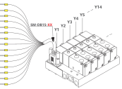
SM-DB15 cable

SM-DB15 control cable
SM-DB15 control cableOpen full-size drawing ↗
ItemValue
ConnectorDB15
Cable referenceSM-DB15-XX

SM-DB25 cable

SM-DB25 control cable
SM-DB25 control cableOpen full-size drawing ↗
ItemValue
ConnectorDB25
Cable referenceSM-DB25-XX

SM-DB15MF cable

ItemValue
Connector codeDB15MF
ConfigurationDual DB15 connectors
17Double-Solenoid Extension Modules

These plug-in extension modules provide the additional coil connection for compatible 4V100 and 4V200 double-solenoid valve arrangements.

Models
4V130-PLUG / 4V230-PLUG
Compatible families
4V100 / 4V200

4V130-PLUG compatibility

4V130-PLUG extension module
4V130-PLUG extension moduleOpen full-size drawing ↗
ModelCompatible valve familyFunction
4V130-PLUG4V100Double-solenoid extension

4V230-PLUG compatibility

4V230-PLUG extension module
4V230-PLUG extension moduleOpen full-size drawing ↗
ModelCompatible valve familyFunction
4V230-PLUG4V200Double-solenoid extension
18Network and Multipin Wiring

Controller connections provide power, network cascading and individual DB15 and DB25 valve outputs. Multipin circuits support NPN sinking and PNP sourcing arrangements.

Supply voltage
24 V DC
Multipin connectors
DB15 / DB25
Output arrangements
NPN / PNP

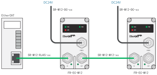
EtherCAT connections

EtherCAT controller power and cascade connections
EtherCAT controller power and cascade connectionsOpen full-size drawing ↗
ConnectionCable or component
Host to first controllerSR-M12-RJ45-XX
Controller to controllerSR-M12-M12-XX
Controller powerSR-M12-DC-XX
ControllerFR-EC-M12

Each controller receives a 24 V DC power connection. The OUT port connects to the IN port of the next controller.

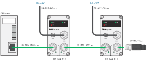
CANopen connections

CANopen controller power, cascade and termination connections
CANopen controller power, cascade and termination connectionsOpen full-size drawing ↗
ConnectionCable or component
Host with pin terminalsSR-M12-E0310-XX
Host with matching RJ45 interfaceSR-M12-RJ45-XX
Controller to controllerSR-M12-M12-XX
Controller powerSR-M12-DC-XX
Last controller terminationSR-M12-T02
ControllerFR-CAN-M12

The host cable must match the host connector and CANopen pin assignment. A terminating resistor connects at the end of the CANopen cascade.

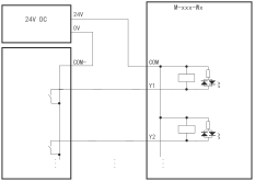
NPN sinking-output wiring

NPN sinking-output wiring
NPN sinking-output wiringOpen full-size drawing ↗
ConnectionSupply reference
Manifold COM+24 V DC
Output-stage COM−0 V
Y1, Y2 and following outputsSwitched to 0 V

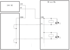
PNP sourcing-output wiring

PNP sourcing-output wiring
PNP sourcing-output wiringOpen full-size drawing ↗
ConnectionSupply reference
Manifold COM0 V
Output-stage COM++24 V DC
Y1, Y2 and following outputsSwitched to +24 V DC

DB25 single-solenoid pin assignments

DB25 single-coil valve output wiring
DB25 single-coil valve output wiringOpen full-size drawing ↗
PinOutputWire marker
1Y1Y1
2Y24Y24
3Y2Y2
4Y23Y23
5Y3Y3
6Y22Y22
7Y4Y4
8Y21Y21
9Y5Y5
10Y20Y20
11Y6Y6
12Y19Y19
13Y7Y7
14Y18Y18
15Y8Y8
16Y17Y17
17Y9Y9
18Y16Y16
19Y10Y10
20Y15Y15
21Y11Y11
22Y14Y14
23Y12Y12
24Y13Y13
25CommonCOM

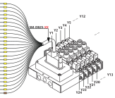
DB25 double-solenoid pin assignments

DB25 double-coil valve output wiring
DB25 double-coil valve output wiringOpen full-size drawing ↗
PinOutputWire marker
1Y1Y1
2Y24Y24
3Y2Y2
4Y23Y23
5Y3Y3
6Y22Y22
7Y4Y4
8Y21Y21
9Y5Y5
10Y20Y20
11Y6Y6
12Y19Y19
13Y7Y7
14Y18Y18
15Y8Y8
16Y17Y17
17Y9Y9
18Y16Y16
19Y10Y10
20Y15Y15
21Y11Y11
22Y14Y14
23Y12Y12
24Y13Y13
25CommonCOM

Y1–Y12 identify one coil bank and Y24–Y13 identify the opposite bank.
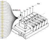
DB15 pin assignments

DB15 valve output wiring
DB15 valve output wiringOpen full-size drawing ↗
PinOutputWire marker
1Y14Y14
2CommonCOM
3Y12Y12
4Y11Y11
5Y13Y13
6Y1Y1
7Y3Y3
8Y5Y5
9Y7Y7
10Y9Y9
11Y2Y2
12Y4Y4
13Y6Y6
14Y8Y8
15Y10Y10

Application review

Valve islands for your machine

Bepto Pneumatic supplies manifolds, control boxes and cables for the valve family, network and coil arrangement in your machine.
Discuss your application
  • 01Valve family and station count
  • 02PLC network or multi-pin connection
  • 03Coil arrangement and 24 V supply
  • 04Port thread and installation dimensions