
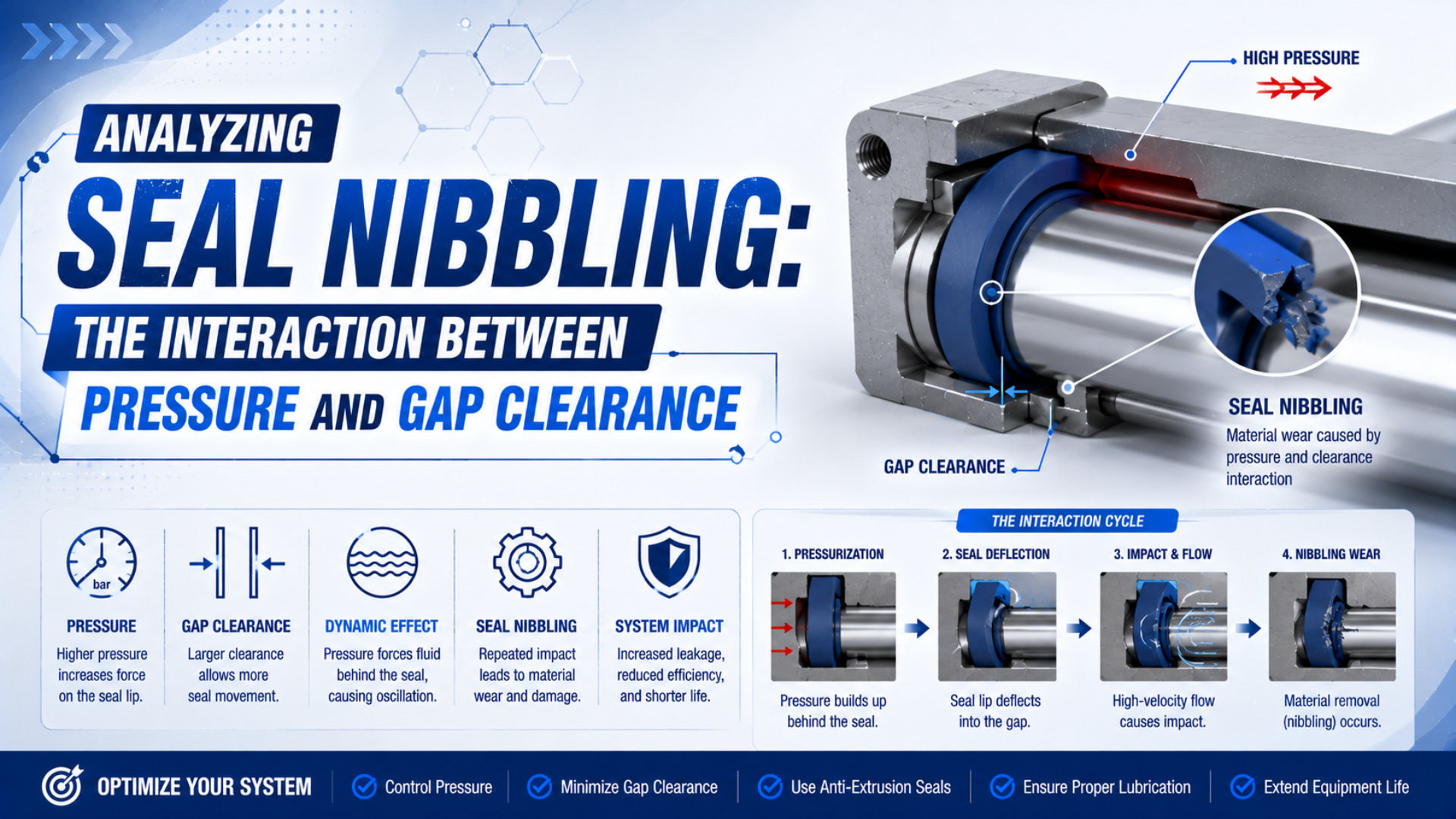
Analyzing Seal Nibbling: The Interaction Between Pressure and Gap Clearance
Seal nibbling is progressive edge damage that occurs when pressure drives elastomer into an unsupported clearance and motion, pressure cycling, or hardware “breathing” pinches or shears the protruding material. A ragged edge near the low-pressure gap is strong evidence, but leakage alone does not prove nibbling.
Diagnosis requires five observations: damage location, pressure direction, maximum local gap, operating-state changes, and the seal supplier’s approved envelope. Replace the seal only after that load path is understood. Otherwise, the same worn guide, enlarged gap, pressure peak, or missing support can damage the next seal.
Key Takeaways
- Ragged low-pressure-side damage supports a nibbling diagnosis.
- Pressure and gap interact, but no universal table covers every seal profile, compound, cross-section, temperature, motion, and duty cycle.
- Measure the worst local gap.
- Preserve seal orientation, pressure direction, groove evidence, and clock position before cleaning or discarding failed parts.

This photograph shows severe edge damage, not a complete diagnosis. Correlate it with the pressure side, groove, support diameter, and operating history.
What Evidence Confirms Seal Nibbling?
Trelleborg gives 2 field clues for extrusion or nibbling: ragged edges generally appear on the low-pressure side, and likely contributors include excessive clearance or system pressure. Parker describes extruded material being jammed in the gap and peeled away as hardware moves (Trelleborg Technical Support; Parker O-Ring Handbook, accessed July 26, 2026).
Seal nibbling is repeated tearing or peeling of seal material after pressure pushes it into a clearance and the moving or flexing hardware traps that protruding edge. Gap extrusion is the deformation that precedes the damage. The terms are related, but extrusion can exist before a visible piece has been removed.
Local extrusion gap is the largest unsupported radial clearance the seal encounters at a particular position and operating state. It can be larger than the centered drawing clearance after tolerance, eccentricity, wear, temperature, and pressure deformation are included.
Leakage is only a symptom.
Look for a linked evidence set:
- ragged material beside the low-pressure gap;
- peeled or scalloped damage that returns at the same clock position and follows the unsupported edge rather than an assembly path;
- eccentricity;
- cycling, reversal, or sliding motion that repeatedly traps the protruding material;
- measurable improvement after the gap, guidance, or support condition is corrected.
One-sided circumference damage deserves extra attention. Trelleborg identifies irregular clearance caused by eccentricity as a contributor. If the seal is chewed only at one clock position, inspect the bearing, wear ring, rod alignment, piston support, and side-load path before specifying a harder compound.
Direction matters.
Why Must Pressure and Gap Be Evaluated Together?
Hallite requires 2 hardware checks, maximum extrusion gap and minimum metal-to-metal clearance, then compares the maximum gap with the selected seal’s product data at working pressure. Its guidance also adds piston-cylinder dilation, showing why pressure, tolerances, and structural deformation cannot be separated (Hallite Housing Designs, accessed July 26, 2026).
Pressure creates the load that drives a seal toward the lower-pressure side. For an exposed seal area, the basic pressure load relationship is:
Here, is the pressure-generated load, is the pressure difference across the seal, and is the effective exposed area. This equation explains why increasing differential pressure increases seal loading. It does not calculate an allowable gap or predict seal life.
Hardware decides the gap.
Use this diagnostic expression:
In this relationship:
- is the largest credible radial gap at the seal after every applicable contributor is included;
- is centered clearance;
- combines guidance clearance, runout, alignment error, and load-induced center offset;
- covers pressure dilation, differential thermal growth, coating loss, and wear accumulated during the service interval.
For the complete tolerance-stack calculation, use the extrusion-gap design guide. During failure analysis, measure the worn assembly, find where the gap accumulated, and compare that state with the exact seal supplier’s limit.
Pressure and clearance do not form a universal multiplication rule. A small nominal gap can still become dangerous at one clock position if the piston or rod shifts under side load. Conversely, a larger cold gap might be approved for a specific profile, cross-section, compound, pressure, temperature, and duty cycle. The product envelope decides.
How Can You Distinguish Nibbling From Similar Seal Damage?
Trelleborg separates extrusion or nibbling from at least 4 nearby failure patterns: abrasion, contamination, compression set, and installation-related damage. Its extrusion description points to ragged low-pressure-side edges, while abrasion produces a flatter worn surface with loose particles and scratches (Trelleborg Technical Support, accessed July 26, 2026).
| Observed evidence | More likely mechanism | Next verification |
|---|---|---|
| Ragged bites or peeled edge beside the low-pressure gap | Extrusion or nibbling | Map pressure direction; measure the local gap and pressure peaks |
| One clean slice or shaved edge | Installation cutting | Inspect lead-in chamfers, burrs, assembly tools, and seal orientation |
| Broad dull wear with parallel scratches | Abrasion | Check surface finish, contamination, lubrication, and wiper condition |
| Damage concentrated at one clock position | Eccentricity or inadequate guidance | Measure bearing clearance, runout, side load, and alignment |
| Swelling, tackiness, hardening, or cracks | Chemical or thermal degradation | Confirm compound, lubricant, washdown chemistry, and temperature |
| Flattened cross-section without ragged loss | Compression set | Check squeeze, groove fill, dwell, temperature, and compound |
Multiple mechanisms can appear on one seal. For example, a worn guide may enlarge the gap, tilt the sliding member, and produce nibbling plus abrasion at the same clock position. Chemical exposure may also soften the elastomer. Keep every clue.
Surface texture can also create convincing false positives. Directional scratches or sharp features can cut the seal without pressure extrusion. Review the cylinder barrel surface-finish guide when the damaged face is broadly polished or scored rather than locally ragged.
A Six-Step Seal-Failure Teardown
According to Parker, O-ring failures can result from several simultaneous factors rather than one isolated cause. A 6-step teardown preserves orientation, pressure direction, groove condition, dimensions, operating data, and comparison evidence before the parts are cleaned or discarded (Parker O-Ring Handbook, accessed July 26, 2026).
Depressurize and isolate the machine under its approved maintenance procedure. Then:
- Mark the cylinder orientation, pressure ports, rod direction, and seal clock position.
- Photograph everything before cleaning.
- Remove the seal without cutting across the suspected damage.
- Mark the high-pressure and low-pressure faces before the seal can rotate.
- Measure the support diameters, bore, groove, guide clearance, runout, and visible wear.
- Compare the failed and unaffected sides, avoid creating a new cut during removal, and retain the seal and debris in a labeled bag.
Measure before cleaning.
In our experience reviewing pneumatic cylinder failures, cleaning the groove before marking the seal orientation destroys the most valuable clue. A small paint mark on the seal, piston, and barrel datum can preserve the clock position long enough to compare the ragged edge with guide wear, port direction, and the maximum measured gap.
How Do Pressure Peaks, Temperature, and Guidance Change the Gap?
Hallite identifies 3 operating effects for an extrusion review: working pressure, temperature, and cylinder dilation. Parker includes tolerances and thermal change. Consequently, room-temperature clearance cannot represent the hot, pressurized, worn state at the end of a service interval (Hallite Housing Designs; Parker O-Ring Selector, accessed July 26, 2026).
Pressure peaks increase the instantaneous seal load and may expand compliant hardware. Record pressure close to the cylinder port with enough sampling speed to capture reversal, cushioning, valve switching, or emergency-stop events. A slow supply gauge can miss a short transient. Temperature also changes metal dimensions and seal response. Do not apply a universal Shore-hardness correction per degree. Use the compound supplier’s temperature data, account for media exposure and aging, and calculate differential expansion from the actual mating materials. Guidance determines where the clearance accumulates. A worn wear ring, rod bearing, or external guide can shift the moving member to one side. The opposite side then sees the maximum local gap. Review the rod-bearing seal-protection guide when damage is concentrated at one angular position.
Dry air, contamination, and surface damage can add abrasion to the same failure. The dynamic-versus-static seal guide explains why a pressure seal that survives a static test may still fail during reciprocating motion.
Which Corrective Action Matches the Evidence?
Two Parker placement rules govern conventional backup rings: a single ring belongs on the non-pressurized side, while reversing pressure normally requires support on both sides. Backup rings reduce the unsupported path, but cannot repair worn guidance, incorrect groove geometry, or an incompatible compound (Parker O-Ring Handbook, accessed July 26, 2026).
Cause comes before cure.
| Evidence-backed cause | Corrective action | Verification after repair |
|---|---|---|
| Local gap exceeds the selected seal limit | Restore the support diameter, bore, wear ring, or gland; revise tolerances if redesigning | Recalculate and measure the maximum local operating gap |
| Missing low-pressure-side support | Install the supplier-approved backup ring or supported seal profile | Confirm ring orientation, groove width, and pressure direction |
| Pressure peak exceeds the approved condition | Correct regulation, switching, cushioning, or circuit behavior | Capture a pressure trace at the relevant operating event |
| One-sided guide wear or misalignment | Repair guidance and remove the side-load or closed tolerance loop | Measure runout, guide clearance, and loaded alignment |
| Assembly cut or shaved edge | Add the specified lead-in, remove burrs, protect threads, and use the correct tool | Inspect the next installed seal before pressurization |
| Compound softened, swelled, or hardened | Select a supplier-approved material for the medium and temperature | Confirm compound identity and exposure limits in writing |
Harder seals are not a general repair. They may increase extrusion resistance in one product family, but can also change friction, low-pressure sealing, installation, and surface requirements. Compare the complete profile and compound, not only a Shore A number.
Effective corrective action changes the failed interface and creates a measurable acceptance test. “Install a seal” proves nothing. A defined gap limit, restored guide clearance, and pressure trace provide repeatable evidence after representative cycling.
Evidence closes the repair.
What Should the Maintenance Record Contain?
Hallite’s method preserves 2 dimensional results: maximum extrusion gap and minimum metal-to-metal clearance. Add the operating evidence. A complete record lets the next inspection detect gradual drift in pressure, guidance, clearance, leakage, or damage location instead of restarting the diagnosis (Hallite Housing Designs, accessed July 26, 2026).
Record:
- asset number;
- seal profile, cross-section, compound, hardness scale, supplier, part number, and manufacturing lot when traceability is available;
- continuous and peak pressure at the cylinder, including pressure direction;
- cold and operating temperature, medium, lubricant, and cleaning chemicals;
- measured bore, support diameter, groove, guide clearance, runout, and local gap;
- speed, cycle rate, load, cushioning, reversal, and failure timing;
- photographs indexed to pressure side, motion direction, and clock position;
- corrective action, replacement parts, measurable acceptance limits, responsible reviewer, and a scheduled follow-up after representative production cycling under the recorded load.
For leakage trending, the Pressure Decay Leak Rate Calculator can convert a controlled isolated-volume pressure decay into an estimated leak rate. It cannot identify nibbling or approve an extrusion gap, so use it only as supporting before-and-after evidence.
Seal Nibbling FAQs
Two source boundaries govern the answers below. Nibbling involves material entering a clearance, and ragged damage generally appears near the low-pressure side. Pressure alone is insufficient because compound, cross-section, temperature, motion, and support geometry change the result (Parker O-Ring Handbook; Trelleborg Technical Support, accessed July 26, 2026).
Can seal nibbling occur at ordinary pneumatic pressure?
Yes. A worn guide, eccentric piston, damaged support surface, soft or incompatible compound, sharp pressure transient, or unusually large local gap can create risk at an otherwise ordinary operating pressure. Do not approve or reject the diagnosis from the supply regulator setting alone. Compare the measured condition with the exact seal supplier’s data.
Which side of the seal should show nibbling damage?
Trelleborg says ragged extrusion or nibbling damage generally appears on the low-pressure side because pressure drives the seal toward that clearance. Mark the seal orientation before removal. If damage appears elsewhere, verify reversing pressure, assembly cuts, surface defects, contamination, and whether the seal rotated after disassembly.
Will a harder seal stop nibbling?
Not by itself. Hardness is one input alongside profile, cross-section, modulus, tear resistance, temperature, medium, motion, and local support gap. Trelleborg’s clearance guidance uses pressure, O-ring cross-section, and hardness together. Use the selected product’s data rather than substituting an unrelated harder seal by color or nominal size.
When is a backup ring required?
Use a backup ring when the selected seal and hardware design call for one at the actual pressure, gap, temperature, motion, and duty cycle. Parker places a single ring on the non-pressurized side and normally supports both sides when pressure reverses. Confirm the groove is designed for the added component.
How can installation damage be separated from nibbling?
Installation damage commonly leaves a clean cut, shave, or slice aligned with a sharp entry edge, burr, thread, or assembly path. Nibbling more often produces repeated ragged loss near the low-pressure clearance. Inspect the lead-in and groove, preserve seal orientation, and correlate the mark with pressure direction before assigning the cause.
Sources and Technical References
- Parker, O-Ring Handbook, PTD5705-EN. Failure analysis and nibbling mechanism.
- Parker, O-Ring Handbook, ORD 5700. Detailed O-ring design tables, clearance checks, backup-ring placement, surface requirements, and dynamic-seal guidance. Retrieved July 26, 2026.
- Parker O-Ring Selector. Tolerance and thermal checks.
- Trelleborg, Technical Support: O-Ring Failure Modes. Visual indicators and contributing factors for extrusion, nibbling, abrasion, contamination, and compression set. Retrieved July 26, 2026.
- Trelleborg, O-Rings and Back-up Rings. Clearance variables and backup rings.
- Hallite, Housing Designs. Worst-case extrusion-gap calculations using tolerance buildup, hardware clearance, bearing arrangement, working pressure, and piston-cylinder dilation. Retrieved July 26, 2026.
Conclusion: Diagnose the Load Path Before Replacing the Seal
Five evidence streams support a defensible nibbling diagnosis: damage morphology, low-pressure-side location, measured local gap, captured operating pressure, and the selected seal’s published envelope. Parker, Trelleborg, and Hallite treat sealing as an interaction among pressure, support, material, geometry, motion, and operating state (Parker O-Ring Handbook; Trelleborg Technical Support; Hallite Housing Designs, accessed July 26, 2026).
Preserve the failed seal’s orientation. Measure the worn hardware at the damage location. Capture the pressure and temperature events that the cylinder actually experiences. Then correct the gap, guidance, support, circuit, assembly method, or material responsible for the failure and repeat the same acceptance checks.
For help reviewing a failed cylinder, send the cylinder series, bore, stroke, seal photographs, pressure direction, measured diameters, guide clearance, pressure trace, temperature, medium, and cycle details through the technical contact page.