

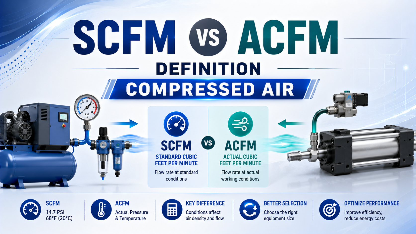
SCFM and ACFM describe the same gas flow on different volume bases. SCFM reports the volume that the air would occupy at a declared reference pressure, temperature, and humidity. ACFM reports volume at stated actual conditions. CAGI lists three common SCFM temperatures, 60°F, 68°F, and 70°F, so an SCFM value is incomplete unless its reference state is named (CAGI, 2020).
That distinction affects compressor comparisons, flowmeter interpretation, pipe velocity, valve selection, and pneumatic cycle calculations. It does not mean one number is more “real” than the other. The useful number is the one whose pressure, temperature, humidity basis, and measurement location match the engineering decision.
Key Takeaways
- SCFM is reference-state volume, not a direct mass-flow unit.
- CAGI documents at least three common SCFM temperature references.
- Convert with absolute pressure and absolute temperature, then state whether ACFM means compressor inlet flow, FAD, or local line volume.
SCFM and ACFM: Two Volume Bases, Not Two Kinds of Air
CAGI defines SCFM as free-air flow converted to specified standard conditions and ACFM as actual volume flow at prevailing compressor conditions. Its compressor guidance also separates inlet CFM, free air delivery, and standardized flow, which prevents one volume number from being applied at the wrong physical location (CAGI, 2026).
SCFM, standard cubic feet per minute, is a volumetric flow rate normalized to a declared reference state. It answers this question: how many cubic feet per minute would this gas occupy if it were brought to the stated standard pressure, temperature, and humidity?
ACFM, actual cubic feet per minute, is volumetric flow at stated local conditions. Those conditions must include the measurement location and enough state information to interpret the number. In compressor work, ACFM often refers to inlet conditions or free-air delivery referred back to inlet conditions. In a pipe calculation, it can mean the volume passing a point at line pressure and temperature.
SCFM is therefore not itself a mass-flow unit. When gas composition and reference conditions are fixed, it corresponds to a particular molar or mass flow, which makes it useful for comparing demand and capacity. ACFM is the number needed when physical volume determines velocity through a pipe, port, valve passage, or meter.
| Flow expression | What the number represents | State that must be declared | Typical use |
|---|---|---|---|
| SCFM | Volume referred to standard conditions | Reference pressure, temperature, humidity | Comparing normalized demand and capacity |
| ACFM at compressor inlet | Volume entering the compressor | Site inlet pressure, temperature, humidity | Compressor selection and site correction |
| FAD | Delivered flow referred to compressor inlet conditions | Test method and inlet conditions | Comparing compressor packages |
| Line ACFM | Local volume passing a point in the compressed-air line | Local absolute pressure and temperature | Pipe velocity and passage sizing |
The unit label is only half of the specification. A useful flow record also names the gas state and the measurement boundary. “100 SCFM at the compressor” and “100 SCFM consumed by a machine” can be compared only after both use the same reference convention and time basis.
In our experience, the most useful correction is often administrative rather than mathematical: add four fields beside every flow value for reference pressure, reference temperature, humidity basis, and measurement location. That small change exposes incompatible numbers before they reach a sizing spreadsheet.
Why Is There No Single Universal SCFM Reference State?
CAGI identifies SCFM references at 14.7 psia and 0% RH with temperatures of 60°F, 68°F, or 70°F. Festo flow sensors provide three references ranging from 0°C dry air to 20°C at 65% RH. These alternatives prove the SCFM reference state cannot be assumed (Festo, 2024).
ISO 8778:2003 specifies a reference atmosphere for pneumatic fluid-power performance data, but an equipment datasheet may use another declared convention. The safe procurement rule is simple: copy the reference pressure, temperature, and humidity into the RFQ or calculation sheet rather than relying on an unstated default.
| Published convention | Absolute pressure | Temperature | Humidity |
|---|---|---|---|
| CAGI examples for SCFM | 14.7 psia | 60°F, 68°F, or 70°F | 0% RH |
| CAGI glossary convention | 14.5 psia | 68°F | 0% RH |
| Festo DIN 1343 display basis | 101.325 kPa | 0°C | 0% RH |
| Festo ISO 2533 display basis | 101.325 kPa | 15°C | 0% RH |
| Festo ISO 6358 display basis | 100 kPa | 20°C | 65% RH |
| SMC ANR | 101.3 kPa | 20°C | 65% RH |
The numerical difference is not always large, but it is real. For the same dry-air molar flow and pressure, a 70°F reference volume is about 1.9% larger than a 60°F reference volume because absolute temperature changes from roughly 520°R to 530°R. That gap can matter when a datasheet limit and a measured demand are close.
The Correct SCFM-to-ACFM Equation
NIST gas-flow guidance warns that standard-volume abbreviations can assume different temperatures, even when the same shorthand is used. For an unchanged dry-gas molar flow, the conversion must use absolute pressure and absolute temperature. A real-gas compressibility factor can be included when the required accuracy and operating state justify it (NIST, 2025).
For dry air flowing steadily between a standard state and an actual state :
Here, is actual volumetric flow, is standard volumetric flow, and are absolute pressures, and are absolute temperatures, and and are compressibility factors. For a first-pass low-pressure air calculation, engineers often take both values as 1 and document that ideal-gas assumption.
The reverse conversion is:
This equation does not create compressor capacity. It only expresses an equivalent gas flow at another state. Pressure drop, valve restriction, leakage, compressor volumetric efficiency, and fluctuating demand require separate calculations or measurements.
For example, converting a point-of-use flow to standard conditions can normalize the demand, but it cannot prove that the upstream valve will pass that flow without excessive pressure loss. The state conversion and the component-flow calculation answer different questions.
Worked example: 50 SCFM at a 90 psig point of use
Assume a dry-air demand of 50 SCFM referenced to 14.5 psia and 68°F. The point of use is at sea-level atmospheric pressure, the line gauge reads 90 psig, and the local air temperature is 95°F. With ideal-gas behavior:
- Standard absolute pressure: 14.5 psia
- Actual line absolute pressure: 90 psig + 14.7 psi atmospheric pressure = 104.7 psia
- Standard absolute temperature: 68°F + 459.67 = 527.67°R
- Actual absolute temperature: 95°F + 459.67 = 554.67°R
The result is approximately 7.3 ACFM at that line measurement point. It is not the compressor’s inlet ACFM rating. The same dry-air flow occupies less volume in the pressurized line because its absolute pressure is much higher than the reference pressure.
Which Pressure and Temperature Values Belong in the Formula?
NIST gives 1 atmosphere as 14.6959 psi and states that gas-flow reference calculations depend on declared temperature and pressure. The conversion therefore requires psia, not psig, and Rankine or kelvins, not Fahrenheit or Celsius. Using gauge pressure or a relative temperature directly breaks the gas-state relationship (NIST, 2025).
Convert local gauge pressure with:
is local absolute pressure, is the gauge reading, and is atmospheric pressure at the site. Do not automatically add 14.7 psi at altitude. Use measured barometric pressure or a defensible site value.
Convert Fahrenheit to Rankine and Celsius to kelvins with:
Absolute temperature is essential because gas volume is proportional to temperature measured from absolute zero. A 10°F difference near room temperature is only about a 1.9% change in absolute temperature, not the much larger ratio obtained by dividing Fahrenheit readings.
Before calculating, write the state pair in one line:
50 SCFM at 14.5 psia, 68°F, 0% RH -> line ACFM at 104.7 psia and 95°F
That line catches most setup errors before they reach the equation.
From our work with compressor and actuator specifications, writing this state pair is more reliable than beginning with a memorized shortcut. It forces the atmospheric-pressure assumption, temperature scale, and intended ACFM location into view while the inputs are still easy to correct.
How Do Humidity and Altitude Change the Result?
CAGI’s 5,000 ft example uses 12.2 psia inlet pressure and subtracts water-vapor partial pressure before converting a 1,000 SCFM requirement to site ACFM. The method shows that altitude and humidity change compressor inlet density; they are not a universal multiplier for line-flow calculations (CAGI, 2021).
For a dry-air basis, the dry-air partial pressure in a moist mixture is:
is dry-air partial pressure, is total absolute pressure, and is water-vapor partial pressure. Relative humidity alone is not enough. The saturation vapor pressure at the measured temperature is also required.
At higher altitude, compressor inlet atmospheric pressure falls. A positive-displacement compressor may ingest nearly the same swept inlet volume while capturing less dry-air mass per revolution. The resulting site correction belongs on the inlet-capacity side of the analysis. It should not be mixed casually with local compressed-line volume at the same gauge reading.
Humidity matters most when:
- compressor capacity is corrected for hot, humid inlet air;
- a mass or thermal flowmeter reports flow on a dry or moist reference basis;
- two suppliers use different humidity conventions;
- measurement uncertainty is small enough that the moisture correction is material.
For routine plant comparisons, the best approach is to use the manufacturer’s declared correction method. A generic “humidity factor” is not traceable and should not appear in an RFQ or acceptance calculation.
Altitude creates two separate engineering questions. It changes compressor inlet density, and it changes the atmospheric term used to convert a local gauge pressure to absolute pressure. Keeping those calculations in separate columns prevents one site correction from being counted twice.
ICFM, FAD, SCFM, and Line ACFM Use Different Boundaries
CAGI lists three compressor flow expressions: inlet CFM, ACFM or FAD measured at delivery but referred to site ambient conditions, and SCFM referred to a declared standard state. These boundaries explain why a compressor datasheet value cannot be compared directly with a pressurized pipe-volume reading (CAGI, 2020).
ICFM is the actual volume entering the compressor inlet under rated inlet conditions. Inlet filters, pressure loss, temperature, humidity, and elevation influence the air density associated with that volume.
FAD, free air delivery, is the delivered compressor flow referred back to the compressor’s inlet conditions under the applicable test method. Atlas Copco similarly defines FAD as delivered gas referred to site atmospheric conditions, unaffected by the compressor (Atlas Copco, 2024).
SCFM converts a flow to a specified reference state. It supports normalized comparison only when the convention is the same.
Line ACFM is the volume physically moving past a chosen point at local pressure and temperature. It is useful for velocity calculations, but a local meter may already display normalized flow. Read the meter setup before treating its screen value as actual volume.
Which Flow Basis Should You Use for Pneumatic Sizing?
CAGI says compressor requirements should specify standardized flow or ACFM/FAD together with design inlet and reference conditions. For pneumatic equipment, use normalized flow to total air demand, then use local actual volume and component flow data where passage area, velocity, and pressure loss control performance (CAGI, 2020).
| Engineering task | Preferred flow basis | Additional information required |
|---|---|---|
| Compare two compressor packages | FAD or SCFM on the same declared basis | Discharge pressure, test method, inlet conditions |
| Total cylinder air demand | SCFM, NL/min, or ANR on one common basis | Bore, stroke, cycles, pressure, acting mode |
| Check pipe or tube velocity | Local ACFM | Local absolute pressure, temperature, internal diameter |
| Select a valve for cylinder speed | Manufacturer flow characteristic plus required normalized flow | Upstream and downstream pressures, gas temperature |
| Interpret a flowmeter | The meter’s configured reference basis | Gas type, display mode, reference state |
| Correct compressor capacity for site | Inlet ACFM and FAD/SCFM | Altitude, inlet temperature, humidity, cooling conditions |
For actuator demand, calculate chamber volume and cycle frequency first. The guide to pneumatic flow-rate calculation covers that workflow. The article on pneumatic cylinder air consumption explains extension and retraction demand.
Flow does not convert directly into pressure. Pressure changes because restrictions, demand, storage, and compressor control interact. Use flow-versus-pressure valve sizing when force and speed are being confused, and use the pressure-drop troubleshooting guide when dynamic pressure falls at the machine.
Once two values are on the same state basis, the Flow Converter can change SCFM, L/min, and m³/h units. It does not convert reference conditions. Perform the pressure-temperature correction first, then change units.
A Procurement Workflow That Prevents Flow-Basis Errors
CAGI’s compressor guidance asks buyers to specify both site inlet conditions and the reference state for SCFM or Nm³/h. A five-line data block can satisfy that requirement and prevent 60°F, 68°F, dry-air, ANR, inlet-flow, and line-flow values from being mixed in one capacity comparison (CAGI, 2020).
Use this sequence:
- Name the measurement boundary. State compressor inlet, compressor FAD, normalized machine demand, or a specific line location.
- Record the gas state. Include absolute pressure, absolute temperature, and humidity convention.
- Record the time basis. Distinguish instantaneous peak, average cycle demand, shift average, and rated continuous capacity.
- Convert once. Select one shared reference state for comparison and keep the original values beside the converted values.
- Check restrictions separately. Use valve flow characteristics, tube diameter, fittings, silencers, and measured dynamic pressure.
- Write the acceptance test. Define where flow and pressure will be measured and which reference setting the instruments will use.
A compact RFQ line can look like this:
Required demand: 250 SCFM at 14.5 psia, 68°F, 0% RH; site inlet: 12.2 psia, 100°F, 50% RH; required discharge: 100 psig; capacity stated as FAD per declared test method.
For instance, if a supplier returns only “250 CFM,” the buyer can ask whether that means inlet ACFM, FAD, SCFM on a named basis, or compressed-line volume. The clarification should happen before price and motor size are compared.
Keep normalized demand and local passage flow in separate worksheet columns. The first column answers “how much dry air must be supplied?” The second answers “how much physical volume passes through this component here?” Most SCFM-versus-ACFM disputes disappear once those two questions stop sharing one unlabeled cell.
In our experience, this two-column split also improves commissioning. The normalized column can be checked against compressor capacity and accumulated demand, while the local-volume column can be checked against pipe area, velocity, valve data, and dynamic pressure at the machine.
SCFM vs ACFM FAQs: What Should Engineers Confirm?
NIST notes that even “sccm” can imply different standard temperatures, while CAGI publishes three common SCFM temperature references. These five checks focus on the information that survives unit conversion: declared reference state, absolute pressure, local measurement boundary, humidity basis, and the difference between normalized demand and physical line volume (NIST, 2025).
Is SCFM always greater than ACFM?
No. SCFM and ACFM are volumes at different states, so their numerical order depends on absolute pressure and temperature. At a typical pressurized point of use, line ACFM is usually lower than the equivalent SCFM. At a hot, low-pressure compressor inlet, inlet ACFM can be higher than the standardized value.
Is SCFM a mass-flow unit?
No. SCFM remains cubic feet per minute, which is a volumetric unit. Because it refers volume to a fixed pressure, temperature, humidity, and gas composition, it corresponds to a defined molar or mass flow. That relationship makes SCFM useful for normalized comparison, but it does not turn cubic feet into pounds or kilograms.
Can I add 14.7 psi to every gauge-pressure reading?
Only when local atmospheric pressure is approximately 14.7 psia. At altitude or during unusual weather, the site atmospheric pressure differs. Use measured barometric pressure when accuracy matters. The conversion requires local absolute pressure, calculated as gauge pressure plus site atmospheric pressure, not gauge pressure plus an automatic sea-level constant.
Does humidity always increase ACFM?
Humidity changes the dry-air density associated with a moist-air volume, but the correction depends on temperature, total pressure, relative humidity, and the chosen dry or moist reference basis. There is no universal “humidity factor.” For compressor inlet correction, use water-vapor partial pressure and the manufacturer’s stated performance method.
Which number should appear on a pneumatic equipment RFQ?
Use the flow basis that matches the purchasing boundary, then state the reference conditions. Compressor RFQs should include FAD or SCFM, discharge pressure, test method, and site inlet conditions. Machine or actuator RFQs should include normalized peak and average demand, required dynamic pressure, cycle timing, and any local ACFM used for pipe velocity.
Sources and technical references
- ISO 8778:2003: Pneumatic fluid power, standard reference atmosphere
- CAGI: Sizing Centrifugal Air Compressors
- CAGI Compressed Air and Gas Handbook, Chapter 4
- CAGI Resource Library and compressed-air glossary
- NIST: Pressure and Gas Flow Unit Conversions
- NIST: Gas Flowmeter Calibrations with the 26 m³ PVTt Standard
- Festo SFAB flow-sensor operating instructions
- SMC PF-series flow-sensor terminology and ANR reference condition
- Atlas Copco: Decoding Air Compressor Acronyms