

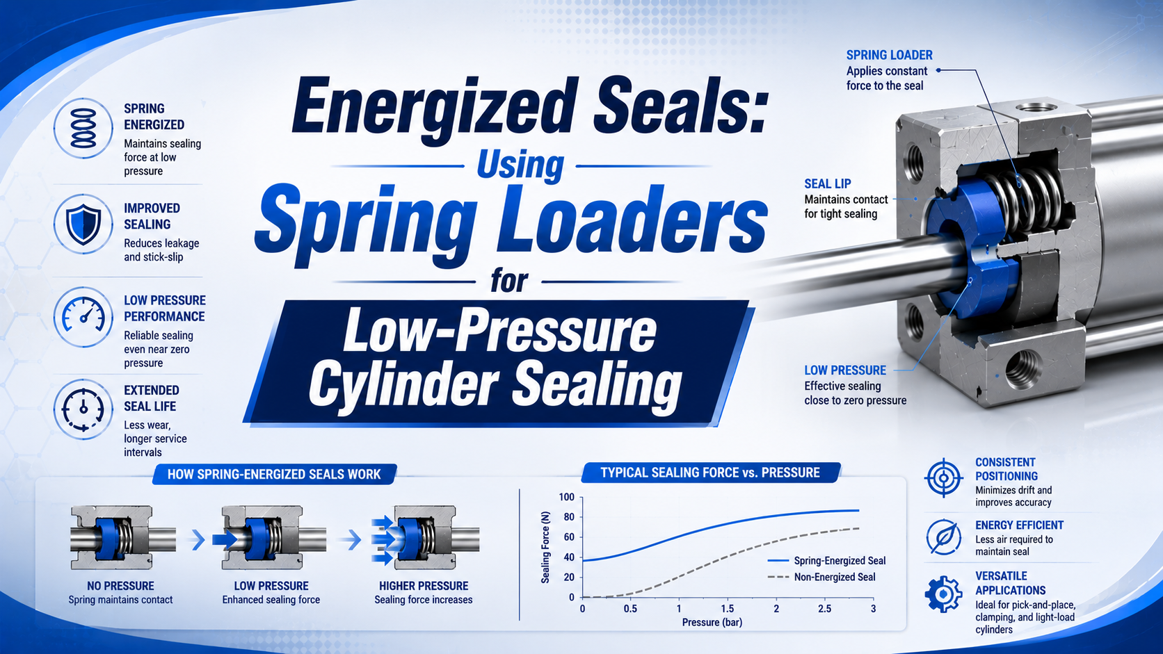
TL;DR: A spring-energized seal uses a metal spring to preload a polymer jacket when system pressure is low. Pressure then adds sealing force. This architecture can help a correctly designed cylinder seal at startup, during pressure variation, or with gas and vacuum service, but it does not cure undersized actuators, trapped exhaust pressure, misalignment, or poor gland geometry. Diagnose the complete axis first, select a manufacturer-defined profile, and validate leakage plus motion over the real operating envelope.
Spring-energized seals for low-pressure cylinders are engineered sealing systems, not universal drop-in upgrades. In Parker’s guide, a spring compressed inside a polymer jacket pushes the sealing lips toward the mating surfaces while system pressure acts on the jacket and increases lip load. Trelleborg describes the same combined action for its Variseal profiles (Parker; Trelleborg, retrieved 2026-07-23).
That mechanism answers one narrow problem: maintaining designed lip contact when fluid pressure contributes little energizing force. It does not make seal friction disappear, guarantee zero leakage, or establish the minimum pressure at which an installed cylinder can move its load.
Key Takeaways
- Conventional O-rings already use installation squeeze to seal at low or zero pressure; they do not rely entirely on air pressure.
- A spring can improve low-pressure lip contact, but increasing spring load also raises friction and wear.
- Spring shape, jacket compound, lip geometry, gland dimensions, surface finish, speed, pressure, medium, and temperature form one qualified system.
- Test port pressures, leakage, breakaway, running motion, and post-dwell restart before approving a cylinder configuration.
What Is a Spring-Energized Seal?
Parker’s PTFE lip-seal guide defines the assembly as a polymer jacket plus a corrosion-resistant metal spring. Installation creates the preload. Compression in the gland pushes the lips toward their mating surfaces before meaningful fluid pressure is present. Pressure later enters the jacket cavity and adds lip load. The result is spring-assisted and pressure-assisted sealing, not pressure independence.
Most jackets provide the sealing lips and the main media-facing surface. PTFE-based compounds often combine low friction with broad chemical resistance. Yet the family name tells an engineer little about the finished seal. Fillers and processing methods change wear and extrusion behavior. Lip geometry affects contact stress. Thermal history influences dimensions. Counterface properties may decide whether the compound survives. “PTFE” alone is not a specification. Spring preload also compensates for tolerance changes. It does not drive the piston. Relaxation and wear are further reasons for mechanical energization. Within a piston seal, force passes radially through the jacket toward the cylinder wall. A rod-seal profile instead directs its working lip toward the rod and supports sealing at the gland. Those different load paths mean the correct spring force and orientation must come from the selected profile rather than the cylinder bore alone.
The useful distinction is not simply “standard seal versus energized seal.” It is where the initial contact load comes from and how that load changes in service. An elastomeric O-ring obtains initial contact from squeeze. A conventional U-cup uses interference and lip geometry, then gains pressure activation. A spring-energized polymer profile adds a defined mechanical energizer. Each can work at low pressure when the entire seal and hardware system is designed for that duty. One concrete example is Parker’s FBC-V, a symmetric spring-energized PTFE rod or piston seal with a cantilever spring. For that named design, Parker lists up to 3,000 psi and 0.5 m/s when it is used with the specified materials and glands (Parker FBC-V, retrieved 2026-07-23). No unnamed seal or cylinder inherits those limits.
That is the rating boundary.
Why Can a Cylinder Struggle at Low Pressure?
SMC publishes 0.005 MPa minimum operating pressure for several smooth-cylinder models, while its single-acting MQP metal-seal cylinder is listed from 0.001 MPa. Those values do not prove that every cylinder should move at the same pressure or that a spring-loaded seal is always the enabling mechanism (SMC, retrieved 2026-07-23).
At low pressure, the actuator has little force margin. A cylinder can hesitate even when its piston seal is not leaking excessively. The active chamber must overcome the external load, gravity, opposing-chamber pressure, seal friction, guide friction, cable drag, and any binding from misalignment. A regulator gauge upstream of the valve cannot resolve that balance.
Separate the symptoms before choosing hardware:
| Observed behavior | Evidence to collect | Plausible cause | Why a new piston seal may not help |
|---|---|---|---|
| Pressure falls while the valve is held | Both port pressures plus isolated leakage test | Internal bypass, valve leakage, tubing leak, or external leak | The measured loss may be outside the cylinder |
| Pressure holds but motion will not start | Port pressures at first motion, load, dwell, alignment | Insufficient net force or high breakaway resistance | More seal preload may increase the resistance |
| Motion starts, stops, and jumps | Position, velocity, command, and two port pressures | Stick-slip, unstable metering, changing load, or binding | The problem is a dynamic system response |
| Speed falls near one stroke location | Position-referenced pressure and mechanical inspection | Guide bind, side load, damaged tube, or local contamination | A seal change cannot correct the load path |
| Cylinder slows near the end only | Cushion setting and exhaust pressure | Over-cushioning or restricted exhaust | The piston seal is not the primary restriction |
A conventional elastomer seal does not wait for air pressure before making contact. Initial contact already exists. Parker’s O-Ring Handbook explains that installation squeeze is most necessary at low or no pressure, then warns that excessive squeeze raises friction and wear (Parker O-Ring Handbook, retrieved 2026-07-23). Therefore, compare qualified designs under stated conditions rather than an “inactive” elastomer with an “always active” spring seal. If the first-motion threshold is the issue, use the procedure in our breakaway-force guide. If the piston moves but repeatedly stutters, the stick-slip measurement guide covers synchronized position and pressure evidence.
Evidence comes before hardware.
Diagnostic Evidence Before Changing the Seal
ISO 10099:2001 remains current after confirmation in 2023 and addresses functional tests and acceptance criteria for double-acting, single-rod pneumatic cylinders. Its scope does not create a universal low-pressure threshold. Build the test plan from the machine’s operating envelope and the selected cylinder’s catalog limits instead (ISO 10099).
Start by documenting the axis as installed. Record the cylinder model, bore, stroke, mounting, orientation, payload, guides, valve, tubing, flow controls, supply pressure, temperature, medium, lubricant policy, cycle rate, and dwell time. Identify whether the complaint is leakage, delayed breakaway, unstable motion, or insufficient force. They require different acceptance metrics.
Then run tests that preserve the fault:
- Measure both cylinder ports.
- Record valve command and position on the same time base, then repeat extension and retraction with the production payload and actual flow-control settings.
- Establish a warm-cycle baseline after stable operation.
- Repeat after the dwell that produces the complaint, preserving supply pressure, load, temperature, direction, tubing, valve state, and metering adjustments.
- Isolate valve and external leakage.
- Inspect alignment, guides, tube condition, contamination, lubrication, and cushions before comparing the evidence with the exact cylinder and seal data; never borrow a minimum pressure from another series.
SMC’s smooth-cylinder instructions note that minimum pressure after mounting includes the cylinder’s own minimum operating pressure plus the effect of guide load and friction. They also call attention to piping and speed-control conditions (SMC Smooth Cylinder, retrieved 2026-07-23). This is the durable lesson: low-pressure performance belongs to the installed axis. A leakage-first diagnosis can miss the real failure. Consider a very tight seal that reduces bypass yet raises breakaway resistance until the piston cannot move at the target pressure, even though a static leak test appears excellent. Approval therefore needs two independent boundaries: allowable leakage and acceptable motion. Both must pass under the same load, speed, temperature, dwell, and direction.
Both limits must pass.
Which Spring Type Fits a Reciprocating Cylinder?
Manufacturer guides distinguish V-shaped cantilever, canted-coil, and helical wound-ribbon energizers. Parker presents the first two for reciprocating service, while its helical spring is intended for static or very slow dynamic service, listed below 150 surface feet per minute. Trelleborg likewise classifies spring families by load and deflection rather than calling them interchangeable.
| Spring architecture | Load behavior described by manufacturers | Typical design reason | Reciprocating-cylinder caution |
|---|---|---|---|
| V-shaped cantilever | Moderate load with useful deflection | Dynamic rod or piston sealing and wiping action | Lip direction and pressure orientation must match the profile |
| Canted-coil or Slantcoil | Relatively constant load over wider deflection | Friction control across tolerance and wear change | The qualified jacket, spring material, and gland remain inseparable |
| Helical wound-ribbon | Higher load with shorter deflection | Gas, vacuum, low-temperature, static, or slow service | Higher spring load can add drag; speed limits are profile-specific |
Do not select by spring name alone. Required lip load changes with gas permeability, surface finish, mating hardness, runout, pressure direction, temperature, jacket relaxation, and allowable friction. The seal supplier should state whether the profile is single-acting or double-acting. They should also define which side faces pressure and whether a separate scraper, bearing, or anti-extrusion element is required. Bidirectional duty complicates the layout. A symmetric double-acting profile or opposed single-acting seals may be considered, but that choice changes trapped volume, friction, assembly space, and pressure response. Never improvise an opposed arrangement from unrelated catalog parts. Obtain a section drawing and the complete gland specification for the exact assembly before releasing the hardware.
Spring names are not ratings.
How Should Jacket Material and Hardware Be Matched?
Bal Seal relates contact stress and friction to seal geometry, material, and energizer force. Geometry is only the start. Parker adds pressure and speed. Mating surface, gland configuration, media, and intended motion also matter (Bal Seal; Parker, retrieved 2026-07-23).
Give the seal manufacturer a duty profile rather than a generic material request:
- Name the medium and contaminants.
- Supply normal, minimum, transient, and proof pressures on both sides of the seal, including any vacuum, pressure reversal, or trapped-pressure case.
- Define speed, stroke, and acceleration.
- Document duty cycle, dwell, startup, cleaning, lubrication policy, and the minimum and maximum hardware temperatures reached during each state.
- Provide mating material, coating, hardness, finish, lead-in geometry, runout, and expected wear.
- Set separate measurable limits for external leakage, internal bypass, first-motion pressure, steady running behavior, and the inspection condition required after the endurance interval.
Virgin PTFE, filled PTFE, and other engineered polymers do not share one temperature, wear, or food-contact status. Compound details matter. A filler that improves wear against one surface may abrade a softer counterface, react poorly with the medium, or alter compliance enough to change leakage and friction. Regulatory suitability belongs to the exact compound, spring, lubricant, manufacturing record, and intended contact path, not to the letters “PTFE.” Surface finish is especially easy to oversimplify. A surface that is too rough can create leakage paths and accelerate jacket wear. A surface that is too smooth for the selected material and lubrication regime may not retain the needed film. Use the finish and hardness values published for the exact seal profile, then confirm the manufacturing process can hold them across the full stroke.
Material and hardware are inseparable.
The dynamic-versus-static cylinder seal guide explains why a seal proven in a stationary pressure test is not automatically suitable for reciprocation. For thermal screening, see the cylinder seal temperature guide.
Retrofit and Installation Requirements
Installation guidance from Parker calls for suitable lead-in chamfers, smooth edges, and dedicated tools on applicable PTFE lip seals. Closed glands may require stretching and resizing. Because PTFE jackets do not recover like ordinary elastomer O-rings, the allowable method comes from the selected profile. One sharp port edge can damage a lip before the cylinder completes a stroke.
Treat a retrofit as a hardware redesign when the existing gland was not cut for the candidate profile. Confirm:
- Verify the gland drawing.
- Check diameter, width, corner radii, concentricity, extrusion clearances, and every tolerance that controls spring compression or jacket support.
- Mark seal orientation and pressure direction.
- Document the installation path, chamfer, edge break, protection over ports and threads, and any stretching, compression, or resizing tools required.
- Inspect the rod, bore, bearing, and wear band.
- Reserve enough axial and radial space for the scraper, backup, bearings, pressure communication, and any opposed seal arrangement shown by the approved design.
Never deepen an existing groove by a generic percentage. The selected manufacturer’s drawing controls gland fill, jacket support, spring compression, radii, and extrusion clearance as a coordinated set of dimensions. Changing only depth can leave the jacket loose, overcompress the spring, remove needed heel support, or create an extrusion path that was absent from the approved section. Before final assembly, reject hardware with scoring, burrs, corrosion, coating damage, or dimensional error outside the seal supplier’s limits. Use only the specified assembly lubricant if lubrication is allowed. Document spring and jacket orientation with a drawing. After assembly, move the seal through its full stroke under controlled conditions before applying the maximum test pressure.
Installation damage is a design failure.
How Should Low-Pressure Performance Be Validated?
ISO 19973-3:2015 provides reliability test procedures for pneumatic piston-rod cylinders and expresses life through cycles or travelled distance. That is the relevant unit. The standard offers no generic life multiplier for one seal architecture, so define the application-specific failure boundary and test duration before testing begins (ISO 19973-3).
Use a test matrix that includes the corners of the real duty envelope, not only one room-temperature bench cycle:
| Test condition | Record | Acceptance purpose |
|---|---|---|
| Minimum commanded pressure, warm | Both port pressures, position, time to first motion, running speed | Confirms basic low-pressure force and motion margin |
| Minimum pressure after defined dwell | Same signals plus dwell duration | Exposes relaxation, lubricant displacement, and breakaway change |
| Maximum speed and cycle rate | Pressure, temperature, velocity, leakage, surface condition | Checks dynamic friction, heating, flow demand, and wear |
| Pressure reversal in both directions | Transient pressures, position response, bypass | Verifies lip orientation and bidirectional behavior |
| Temperature and media boundaries | Leakage, friction, dimensions, jacket condition | Confirms compound and spring suitability |
| Defined endurance interval | Cycles or travel, trend data, teardown findings | Measures degradation against a written failure criterion |
Measure internal bypass only after isolating the valve and external circuit. Check external leakage separately. A pressure-decay result from the complete machine is not automatically a piston-seal value because fittings, tubing, valves, rod seals, and instrumentation may all contribute. Any reported decay needs the test volume, stabilization time, temperature, instrument accuracy, valve state, pressure range, and calculation method beside it. Motion acceptance needs both starting and running behavior. Record active and opposing port pressures at first detectable motion. Evaluate smoothness in a defined stroke window away from acceleration and cushioning unless those regions are the test target. Repeat after the worst credible dwell, because seal contact and lubricant distribution may change while stationary.
After endurance, inspect everything in the load and sealing path: jacket, spring, bore or rod, gland, bearings, counterface, deposits, and lubricant. Compare the leakage and motion traces with baseline data using the same instruments and conditions. Passing initial leakage is not enough if breakaway pressure steadily rises.
Qualification ends with evidence.
Engineering Conclusion
Spring energizers can maintain intentional lip contact when pneumatic pressure contributes little sealing force. That mechanism makes them candidates for selected gas, vacuum, variable-pressure, and low-load duties in which the manufacturer has qualified the profile, gland, spring, jacket, hardware, and service conditions together. It does not make them a universal remedy.
Start with port-pressure and motion evidence. Eliminate valve leakage, external leaks, blocked exhaust, insufficient force, side load, binding, and cushion faults. If the evidence still shows a seal-design gap, choose a manufacturer-defined jacket, spring, lip profile, gland, and hardware finish as one system.
The final decision belongs to a written acceptance test. Leakage, breakaway, steady motion, post-dwell restart, temperature, media exposure, and wear must all pass on the installed axis. A spring-energized seal earns approval through that evidence, not through an unsupported pressure threshold or a generic service-life promise.
This is the approval boundary.
Spring-Energized Seal FAQs: What Should Engineers Ask?
Published Parker, Trelleborg, Bal Seal, and SMC behavior belongs to named configurations, not an unrestricted seal category. The five answers below turn that boundary into procurement questions, supplier-document requests, and acceptance evidence for the installed cylinder, valve, piping, and control method.
Do standard pneumatic seals rely entirely on system pressure?
No. Squeeze creates contact. Elastomeric O-rings use installation squeeze, while many lip seals begin with interference and profile geometry before pressure adds energization. The Parker handbook emphasizes that squeeze is especially necessary at low or no pressure. A spring-energized profile adds a metal preload element; it does not invent initial sealing contact.
Will a spring-energized seal eliminate low-pressure leakage?
No seal guarantees zero leakage across every condition. Damage changes the result quickly. Even with intact hardware, leakage depends on jacket material, lip geometry, gland dimensions, mating finish, contamination, media, temperature, pressure direction, and installation. Set a measurable limit, then verify it on the actual configuration.
Can I install a spring-loaded seal in an existing O-ring groove?
Only with the seal manufacturer’s explicit approval for that exact gland and profile. Spring-energized PTFE seals may require different diameters, widths, support surfaces, lead-in chamfers, extrusion clearances, and assembly tools. A generic groove percentage is invalid. Use the supplier’s complete section drawing and tolerances.
Does more spring force always improve sealing?
No. Higher spring load can raise contact stress and help with difficult media or surface conditions, but it also increases friction and may accelerate wear. Trelleborg and Parker distinguish spring families by load and deflection for this reason. Select the lowest qualified load that passes leakage and motion requirements together.
What should be included in a low-pressure cylinder acceptance test?
Record both port pressures and the valve command. Capture position and load on the same time base so each pressure change can be matched to piston response under the production load. Preserve direction with every result. Also state temperature and speed. Report dwell separately. Test leakage separately from motion. Verify first movement and steady travel. Check reversal and restart after the defined dwell. Repeat at medium and temperature limits. Inspect the seal and hardware after a stated cycle or travel interval.
Sources and technical references
- Parker Hannifin, PTFE Lip Seal Design Guide, Catalog EPS 5340. Used for spring and pressure energization, spring-family selection, hardware requirements, surface considerations, installation, and profile-specific ratings. Retrieved 2026-07-23.
- Parker Hannifin, Parker O-Ring Handbook, ORD 5700. Used for the role of squeeze at low or no pressure and the friction and wear consequence of excess squeeze. Retrieved 2026-07-23.
- Parker Hannifin, FBC-V Low-Friction FlexiSeal. Used only for the named design’s cantilever spring, symmetric rod or piston use, 3,000 psi rating, and 0.5 m/s maximum speed under its specified configuration. Retrieved 2026-07-23.
- Trelleborg Sealing Solutions, Turcon Variseal Catalogue. Used for jacket pressurization, spring preload, wear compensation, and differences among helical, Slantcoil, and V-spring load and deflection behavior. Retrieved 2026-07-23.
- Bal Seal Engineering, Spring-Energized Seal Overview. Used for the relationship among installation compression, contact stress, friction, material, geometry, and energizer force. Retrieved 2026-07-23.
- SMC, MQQ, MQM, and MQP Low-Friction Cylinder Catalogue. Used only for model-specific 0.005 MPa and 0.001 MPa minimum operating-pressure examples. Retrieved 2026-07-23.
- SMC, Smooth Cylinder Supplement. Used for the effect of installed guide load, friction, piping, and speed-control conditions on minimum operating pressure. Retrieved 2026-07-23.
- ISO 10099:2001, Pneumatic fluid power, Cylinders, Final examination and acceptance criteria. Used to establish the scope of functional testing and final examination; ISO confirmed the edition as current in 2023. Retrieved 2026-07-23.
- ISO 19973-3:2015, Pneumatic fluid power, Assessment of component reliability by testing, Part 3: Cylinders with piston rod. Used for cycle or travel-based cylinder reliability testing rather than generic life multipliers. Retrieved 2026-07-23.