

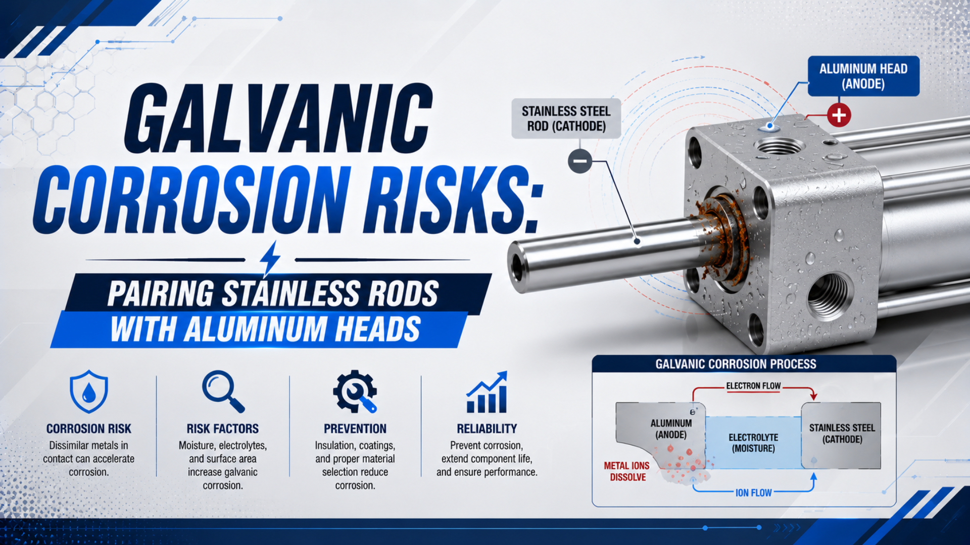
Pairing a stainless piston rod with an aluminum cylinder head does not automatically create damaging galvanic corrosion. A real cell needs two things: an electrical bridge and a conductive liquid reaching both surfaces. Many pneumatic cylinders place a rod seal around the moving rod. A separate bearing or bushing controls its path through the head.
Instead of asking whether stainless steel differs from aluminum, trace the current path across the assembled interface through drawings plus installed hardware. Surface treatments matter. So do seals, drainage, compressed-air quality, and acceptance tests.
Key Takeaways
- One Norgren design combines a 303 stainless rod, aluminum end caps, and a bronze rod bushing.
- Dissimilar materials alone don’t prove a galvanic cell.
- Audit the assembled current path and shared electrolyte.
- Protect faying surfaces, edges, fasteners, drainage paths, and coating defects.
Does a Stainless Rod Actually Touch the Aluminum Head?
Norgren’s Tough Duty Roundline catalog identifies a 303 stainless piston rod operating within aluminum end caps rather than an all-stainless assembly. Separate callouts name a sintered-bronze rod bushing. Buna N rod seals complete the stack (IMI Norgren, retrieved 2026-07-23).
Inside the front head, a seal and bearing element normally control the rod’s functional contact. These components support alignment as well as pressure retention. They also exclude contamination and separate surfaces geometrically. Electrical isolation is possible, but it has to be verified for the installed materials. Don’t infer the current path from an exploded bill of materials. A bronze or metal-polymer bearing can conduct, while a retaining ring may bridge rod-side hardware to the head. Stainless fasteners can cut through a surface treatment. Conductive debris or a wet mounting bracket creates another possible route outside the rod bore.
The distinction changes the purchase decision. A stainless rod can be a sensible wear and corrosion choice with an aluminum head when the assembly controls electrical continuity and liquid ingress. Conversely, an expensive stainless rod doesn’t protect an untreated aluminum fastener hole that stays wet under a large stainless bracket.
The material pair is only the first screen. The assembly stack is the real corrosion circuit.
What Creates a Galvanic Cell at the Rod-to-Head Interface?
Galvanic corrosion is accelerated attack on the anodic member of a dissimilar-material couple within a corrosive electrolyte. AMPP explains that the cathodic member corrodes more slowly than it would alone. Electrical contact and the electrolyte are both required (AMPP, retrieved 2026-07-23).
Four conditions must coincide at the cylinder:
- Dissimilar conductive materials. Specify the exact aluminum alloy, stainless grade, plating, conversion coating, anodizing, and surface condition. Generic material names hide the state that the electrolyte actually sees.
- An electrical bridge. Direct contact is one route. Fasteners, bushings, retainers, mounting hardware, conductive contamination, and damaged isolation can form others.
- A shared electrolyte. Wash water, salt solution, condensate, cleaner residue, or contaminated process liquid must reach both members of the active couple.
- A sustained reaction path. Wet duration, oxygen, chemistry, deposits, temperature, and surface condition influence whether the cell remains active.
Remove one essential condition and the galvanic mechanism stops, although chemical attack or crevice corrosion can still damage the joint. Pitting, fretting, and coating failure remain possible too. White aluminum product therefore proves only that aluminum has corroded. It doesn’t identify the stainless rod as the cause. ASTM G82-98(2021)e1 states that a galvanic series applies to metals exposed to a common electrolyte. The ranking is not a universal voltage table. Surface passivity and solution chemistry can alter behavior; temperature, oxygen, and deposits also matter. A fixed voltage claim needs a defined environment and measurement method.
For a broader investigation after damage has occurred, use our galvanic corrosion failure-analysis guide. This article stays narrower: it addresses how to specify and accept the stainless-rod-to-aluminum-head interface before release.
Where Can the Electrical Bridge Hide?
Festo’s CRDNG repair instructions list five elements in one bearing-cap arrangement: cap, O-ring, cushioning seal, piston rod seal, and bearing. Some variants add a sleeve plus adapter. Festo warns that construction differs by series and must be confirmed before repair (Festo, retrieved 2026-07-23).
That warning belongs in a design review. Two cylinders with the same bore and stroke can use different bearings, retainers, fasteners, surface treatments, and cap architectures. Check every plausible bridge rather than marking one line between “rod” and “head.”
| Possible bridge | What to inspect | What breaks the path |
|---|---|---|
| Rod bearing or bushing | Material, backing, press fit, retaining hardware, contact with rod and head | Qualified non-conductive bearing system or an isolated bearing seat |
| Rod seal hardware | Metallic energizer, retainer, washer, garter spring, contamination | Verified separation from both electrodes and controlled cleanliness |
| Tie rods and cap screws | Finish damage under heads, thread engagement, washers, conductive sealant | Compatible coating system, inert isolation where permitted, sealed edges |
| Mounting bracket | Wetted area, paint damage, stainless bracket footprint, trapped liquid | Isolating pad, sealed fastener stack, drainage, smaller exposed cathodic area |
| Port fittings and sensors | Thread material, locknut, cable shield, metal conduit, wet sensor groove | Compatible interface, sealed penetration, non-wicking isolation |
| Conductive contamination | Metal swarf, carbon-rich debris, dirty grease, salt deposits | Cleaning control, protected assembly, contamination exclusion |
A continuity reading describes only the tested configuration; it isn’t a universal pass/fail number. Probe location plus surface films can change the result because the instrument sees the assembled contact state rather than a material name. Record lead resistance. The drawing should identify intended isolation points and unavoidable electrical bonds.
How Should the Aluminum Head Be Protected?
MIL-STD-889D was validated for continued acquisition use on April 29, 2026. The standard covers galvanic compatibility of conductive materials and recommends protection for dissimilar couples; its Revision D methodology does not treat potential difference alone as a true corrosion-rate predictor (DLA ASSIST, 2026).
For a non-electrical pneumatic joint, protection should work through several independent controls:
- Exclude liquid. Seal faying edges and stop wash water from wicking behind the cap.
- Interrupt unnecessary continuity. Use a non-absorbing inert washer, sleeve, gasket, or bearing material where load, temperature, creep, and assembly requirements allow. The isolation part must survive assembly preload and service motion without creating misalignment.
- Protect the exposed aluminum. Specify surface preparation, treatment, coating coverage, sealing, thickness or process class, and inspection. Include threads, counterbores, edges, ports, and masked areas.
- Control the cathodic footprint. Don’t leave a broad stainless bracket wet beside one small scratch in aluminum.
- Provide drainage and inspection access. A sealed joint needs verified sealing. An open joint needs a deliberate path to drain and dry, plus enough access to see damage before it reaches a bearing seat or pressure boundary.
Anodizing is part of a protection system, not a guarantee of electrical isolation. Machined threads and pressed bearing seats can expose the base alloy. Sharp edges, masked surfaces, fastening damage, and later scratches create other openings. The RFQ must say where continuity is allowed and how the finished assembly will be checked. FAA AC 43-4B describes chemical conversion treatment as a protective film that can improve corrosion resistance and paint adhesion on aluminum. Aviation guidance doesn’t specify a pneumatic-cylinder finish, but it supports one transferable rule: apply the prescribed pretreatment to the surface that will actually enter service (FAA AC 43-4B, 2018).
Coating only the aluminum member deserves special care. If most aluminum stays insulated while a small defect remains connected to a large wetted stainless area, current can concentrate at that defect. Cover edges and fastener holes, control assembly damage, and define repair limits instead of approving a coated drawing with no defect plan.
A corrosion-control note that names only the coating is incomplete. It must also identify the joint edge, damage route, exposed area, and electrolyte-exclusion method.
Exposure Routes: External Washdown and Internal Condensate
ISO 8573-1:2010 classifies compressed-air purity for particles, water, and oil without assigning one moisture class to every cylinder application. ISO 8573-3 separately defines humidity measurement methods plus their limitations (ISO 8573-1; ISO 8573-3).
External and internal liquids reach different parts of the assembly:
| Exposure route | Likely wet surfaces | Design response | Evidence to request |
|---|---|---|---|
| Washdown or rain | Rod exit, cap face, mounting bracket, fastener heads, sensor groove | Edge sealing, compatible external hardware, drainage, wiper protection | Installation orientation, cleaning chemistry, wetting inspection |
| Salt spray | Broad external stainless surfaces and small coating defects | Reduce exposed area imbalance, isolate joints, specify coating repair | Salt exposure description, material certificates, coating records |
| Temperature cycling | Hidden faying surfaces and cold pockets | Vent or seal deliberately, avoid water traps, verify drying | Minimum surface temperature, humidity, duty and shutdown cycle |
| Wet compressed air | Internal cap cavities, barrel, cushioning passages, fasteners exposed internally | Dryer and drain strategy, point-of-use air specification | ISO 8573-1 class at the point of use, pressure dew point record |
| Cleaner or process splash | External seals, anodized surfaces, ports, brackets | Chemical-compatibility review and rinsing plan | Product name, concentration, temperature, contact time |
CAGI’s compressed-air treatment handbook lists rust and scale among moisture-related problems. Increased pneumatic-device wear and sluggish cylinder operation appear in the same list. Cooling after compression also produces condensate (CAGI, retrieved 2026-07-23). Don’t assume a dryer solves external washdown. An IP-rated sensor doesn’t solve internal condensate either. Specify both exposure paths. The pressure dew point guide helps define internal moisture control, while our stainless cylinder selection guide covers food and beverage washdown.
Location at failure matters. Corrosion around external stainless mounting bolts points toward a different bridge from damage inside the bearing cap. Mapping the wet path before choosing a material upgrade prevents an all-stainless rod from being used as a cure for water trapped under a bracket.
Joint Design and RFQ Requirements
NASA-STD-6012A requires assembly-level evaluation for incompatible combinations within its scope and says test-electrode area ratios should match the exposed design areas. Pneumatic buyers can apply that principle without importing NASA qualification limits (NASA-STD-6012A, 2022).
Send enough information for the supplier to identify the current path and the liquid path:
- Component identity. Cylinder series, bore, stroke, action, mounting, cushion type, rod extension, ports, sensors, and drawing revision.
- Exact materials. Stainless grade and condition; aluminum alloy and temper; bearing, bushing, retainer, fastener, fitting, bracket, and insert materials.
- Surface systems. Rod finish; aluminum pretreatment, anodizing, sealing, primer, and topcoat; fastener plating; masked regions; permitted touch-up.
- Interface stack. Section drawing through the rod seal and bearing, plus fastener, mounting, and port details. Identify intended conductive and isolated interfaces.
- Exposure. External liquid chemistry, conductivity if known, temperature, wet duration, drying cycle, salt or cleaner deposits, internal air purity, and pressure dew point.
- Geometry. Exposed anodic and cathodic areas, drainage direction, crevices, coating edges, fastener holes, and inspection access.
- Protection. Gasket or sleeve material, sealant, corrosion-inhibiting compound, coating repair method, and installation controls.
- Acceptance. Material certificates, process records, visual criteria, continuity checks, coating inspection, leakage test, and exposure validation.
Avoid a bare requirement such as “stainless rod with anodized aluminum head.” It doesn’t specify whether the anodizing is decorative or functional. Bearing-seat treatment, bare threads, and fastener bridges remain unknown. Likewise, all-stainless hardware may increase the wetted cathodic area at an aluminum defect. Coastal equipment also needs the exposure-zone questions in the marine corrosion-resistant cylinder guide. Match the material package to salt, drainage, mounting, and inspection conditions rather than a generic marine-grade label.
RFQ decision table
| Buyer finding | Procurement response | Acceptance focus |
|---|---|---|
| Rod is separated by a qualified non-conductive bearing and seal stack | Keep mixed materials if exposure and load requirements are met | Isolation after assembly, bearing integrity, liquid exclusion |
| Metallic bearing or retainer bridges rod and head | Treat the assembly as electrically connected | Shared-electrolyte exposure, finish coverage, area control |
| Stainless bracket covers a small damaged aluminum area | Redesign the mount or isolate and seal the footprint | Bracket drainage, coating damage, exposed area |
| Wet compressed air reaches internal aluminum surfaces | Define point-of-use water class and dew point | Air-quality records, drains, internal corrosion inspection |
| Cleaner attacks coating or seal | Change the chemical, surface system, or sealing package | Compatibility evidence at concentration and temperature |
How Should the Assembly Be Inspected and Accepted?
ASTM G71-81(2024) covers galvanic tests using two dissimilar metals in electrical contact within a low-flow electrolyte. It requires attention to materials, specimen preparation, environment, exposure method, and result evaluation. A cylinder acceptance plan needs the same traceability even when it uses an assembly test instead of a laboratory couple (ASTM G71, 2024).
Use layered evidence:
| Inspection layer | Check | Limitation |
|---|---|---|
| Documents | Alloy certificates, finish specification, lot records, bearing and fastener materials | Paperwork cannot prove intact assembly isolation |
| Surface | Coverage, scratches, exposed edges, masked regions, thread treatment, sealant continuity | Appearance cannot quantify galvanic current |
| Geometry | Drainage, bracket footprint, crevices, exposed areas, installation orientation | Dry inspection may miss the service wet path |
| Electrical | Continuity between specified points on the assembled cylinder | One resistance value doesn’t reproduce electrolyte chemistry |
| Pneumatic | Leakage, breakaway, smooth travel, cushion function, sensor operation | Functional success doesn’t prove long-term corrosion resistance |
| Exposure | Representative liquid, wet/dry cycle, temperature, orientation, duration | Results apply only to the stated test boundary |
Write probe locations and assembly state into the inspection plan. A continuity check after bearing removal answers a different question from a production-stack reading. Cleaning deposits changes the tested route too. Confirm instrument zero and lead resistance; record installed sealant, washers, fittings, sensors, and brackets. Wet tests should use the actual liquid or a justified substitute. ASTM G71 has a low-flow boundary, so stagnant wash solution isn’t equivalent to high-velocity erosion. Artificial seawater data doesn’t automatically predict alkaline cleaner service. Define whether the test is screening, process qualification, or service simulation.
Finish with a normal cylinder functional test. Festo’s repair procedure calls for a functional test after the bearing cap, seals, and tie rods are reassembled. Corrosion controls must not compromise bearing support, sealing, alignment, fastener preload, sensor grounding requirements, or safe motion.
Acceptance is a connected record linking the approved drawing to process lots plus photographs of protected interfaces. Name every continuity probe point. Attach the exposure conditions together with leakage and motion results. Close the package with approved deviations plus repair instructions.
Coupon evidence qualifies a material process. Only the assembled stack can show whether production hardware recreated the intended isolation and drainage paths.
How Should Existing Damage Be Triaged?
FAA guidance describes aluminum corrosion products as white or gray powder. It also recognizes pitting as a possible attack form. Those observations identify the affected material, not the stainless rod as the cause. Preserve the joint before cleaning (FAA AC 43-206, 2001).
Begin with safe isolation and stored-energy control. One photograph should show the installed orientation; close views then record drainage, spray direction, bracket position, rod extension, and deposit boundaries. Preserve loose products when a laboratory review may be needed.
Then separate three decisions:
- Is the cylinder safe to return to service? Measure pit depth, remaining section, seal-groove condition, bearing fit, thread damage, and pressure-boundary integrity against the manufacturer’s limits.
- Is the mechanism galvanic? Prove a conductive bridge and a shared electrolyte. Compare damage on the suspected aluminum anode with an uncoupled or protected area under similar exposure.
- Will cleaning or coating restore the design? Surface cleanup cannot replace dissolved metal. A repair needs dimensional acceptance, a qualified surface process, and confirmation that the original bridge or wet path has been removed.
Don’t use a generic service-life timeline as a diagnostic shortcut. The same pair can stay dry in one machine yet remain wet behind another bracket. Chemistry plus geometry change the result. Surface state and exposure cycle do too. Fixed six-month or eighteen-month forecasts hide those variables. For a full evidence tree covering chemical attack plus crevice corrosion, follow the cylinder galvanic failure-analysis workflow. Better drawings and acceptance records should feed that investigation.
Engineering Conclusion
Taken together the Norgren plus Festo records support a precise procurement conclusion: stainless rods can operate within aluminum-ended cylinders when the complete bearing and seal stack prevents unwanted continuity from overlapping with one shared liquid path through the finished assembly under the stated wetting cycle plus maintenance conditions. Catalog materials alone cannot prove that path.
Approve the pair when the supplier identifies the alloys, surfaces, bearing and seal stack, fastener routes, exposed areas, electrolyte controls, drainage, and acceptance evidence. Reject claims based only on a generic galvanic-series voltage or a promised service-life multiplier.
The strongest design breaks the circuit twice. First, it interrupts unnecessary continuity. Then it excludes the shared liquid. Coating edges and fastener holes remain inspectable, as do drain paths plus isolation parts.
Stainless Rod and Aluminum Head FAQs: What Should Buyers Ask?
ASTM G71:2024 addresses material selection plus specimen preparation for one galvanic test. It also covers electrical contact, electrolyte, exposure, and result evaluation. These five questions translate that boundary into a cylinder RFQ instead of letting material names substitute for evidence about the finished assembly and its wet environment.
Does a stainless piston rod always cause an aluminum head to corrode?
No. Galvanic corrosion needs both an electrical bridge and a shared conductive liquid. A rod seal or bearing may separate the rod from the aluminum head. Fasteners and metallic bushings can create another route. Review the exact assembly plus its exposure instead of treating the material pair as an automatic failure.
Is anodizing enough to isolate the aluminum head?
Not by itself. Threads, bearing seats, edges, masked surfaces, installation damage, and later scratches can expose aluminum or restore continuity. Specify the complete surface process and permitted defects. Add liquid exclusion plus suitable isolation parts. Specify drainage as well. Where isolation is intended, verify it on the assembled joint.
Should stainless fasteners be avoided in an aluminum head?
Not automatically. The decision depends on fastener finish and exposed area. Joint sealing matters too, along with the washer or sleeve system. Check mechanical load plus the expected electrolyte. Stainless hardware can be acceptable when the protection is verified. A broad wetted stainless footprint beside a small aluminum defect deserves particular scrutiny.
Can a resistance reading predict galvanic corrosion life?
No. A continuity test shows whether the tested points are electrically connected under that assembly condition. The reading cannot reproduce the service electrolyte or wet duration. It also omits oxygen availability plus polarization behavior. Exposed area and coating degradation remain outside the test. Record probe locations instead of converting ohms into a service-life claim.
Does dry compressed air eliminate the risk?
It can reduce internal moisture. External washdown remains. Rain and salt spray do too. Cleaner residue or liquid trapped behind a mount needs separate control. Define ISO 8573-1 water purity at the point of use, then address external wetting through drainage, joint sealing, and coating-damage inspection.
Sources and technical references
Corrosion fundamentals: AMPP Galvanic Corrosion. Test boundaries: ASTM G71-81(2024) and ASTM G82-98(2021)e1.
Protection guidance: MIL-STD-889D through DLA ASSIST. Assembly guidance: NASA-STD-6012A plus FAA AC 43-4B.
Cylinder construction: IMI Norgren Tough Duty Roundline Cylinder plus Festo CRDNG Repair Instructions. Compressed air: ISO 8573-1:2010, ISO 8573-3:1999, and CAGI Compressed Air Treatment.