

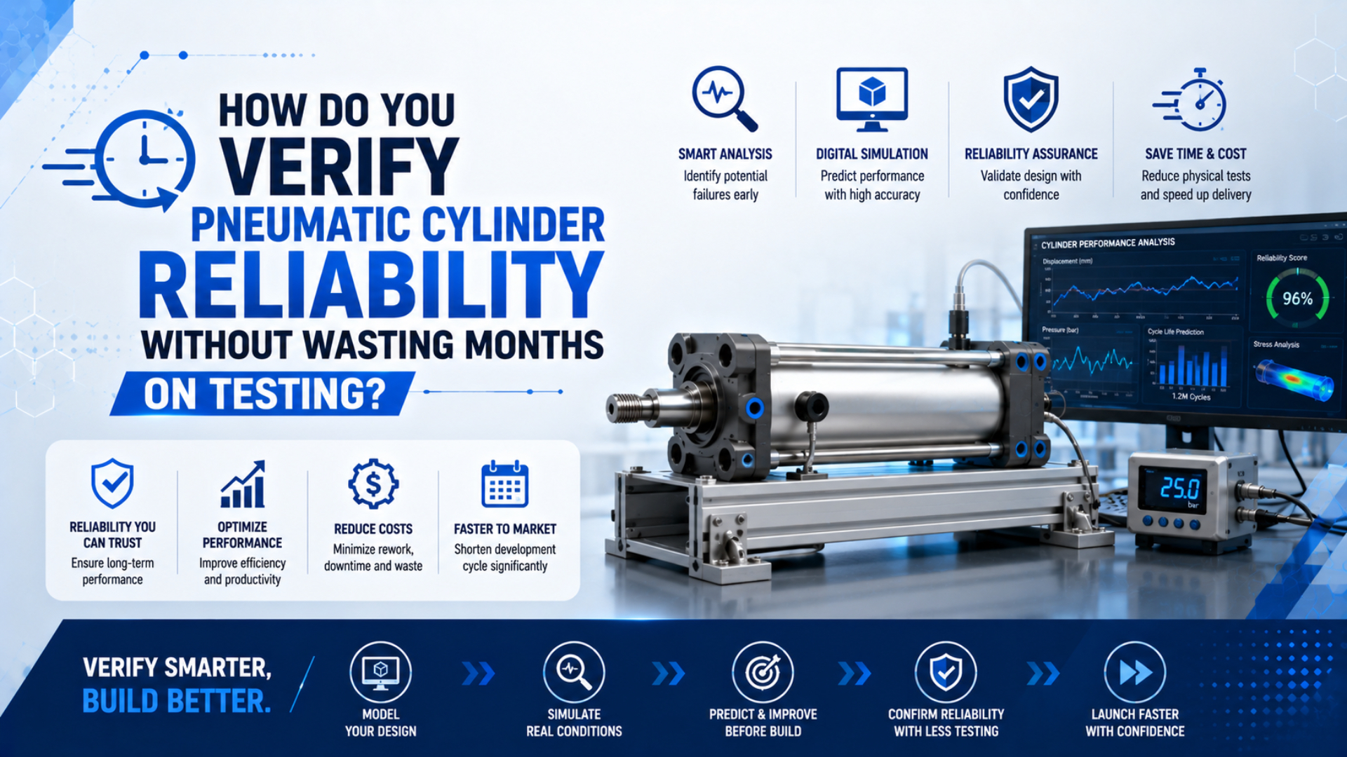
You verify pneumatic cylinder reliability faster by removing idle test time, not by applying an arbitrary stress multiplier. Define the duty and failure threshold first. Then test the dominant failure mechanisms in parallel, monitor measurable degradation, and accelerate only those mechanisms that have a defensible stress-life relationship. A short test without that chain creates an early report, not reliable evidence.
ISO 19973-1 treats component life as a statistical quantity and provides general procedures for test conditions, data evaluation, and reporting. ISO 19973-3 adds procedures for piston-rod cylinders and expresses life in cycles or kilometres. Neither standard converts a few weeks on a rig into a universal number of field years (ISO 19973-1; ISO 19973-3).
The practical way to save calendar time is to make every test answer a defined question. A representative endurance test checks the complete duty. Focused environmental tests expose specific weaknesses. An accelerated life test supports extrapolation only after its model and assumptions survive review.
Key Takeaways
- ISO 19973 evaluates cylinder life statistically, not from one surviving sample.
- A 90% reliability claim at 90% confidence requires 22 independent zero-failure missions under a simple binomial demonstration.
- Acceleration must preserve the field failure mechanism.
- Salt spray and vibration are targeted screens, not automatic life predictors.
1. What Reliability Claim Must the Test Prove?
ISO 19973-3 uses cycles or kilometres as the practical life variable for pneumatic cylinders, while ISO 19973-1 requires statistical evaluation because component service life varies. Start by defining the claimed duty, population, failure event, and confidence statement. “Ran for two weeks” is a test record, not a reliability requirement (ISO 19973-1; ISO 19973-3).
A useful reliability requirement identifies five things:
- Population: exact cylinder series, bore, stroke, seal option, lubricant policy, manufacturing revision, and supplier lot.
- Mission: load, speed, pressure, cycle pattern, dwell, travel distance, mounting, guidance, cushioning, and environment.
- Failure threshold: the measured point at which the unit no longer satisfies its function.
- Reliability target: the required probability of completing the stated mission.
- Statistical confidence: the evidence strength required before accepting that reliability claim.
Without those definitions, teams often test different questions on the same rig. One engineer watches for catastrophic fracture. Another stops at a leakage limit. A third accepts any cylinder that still moves. Their cycle counts cannot be combined because their failure events differ.
Write measurable thresholds before testing. These can include external leakage, stroke-time drift, minimum dynamic pressure, breakaway pressure, carriage play, seal wear, cushion adjustment, end-position repeatability, or visible corrosion at a specified location. The threshold should come from the machine requirement, product specification, or agreed qualification plan.
| Duty input | Record before rig design | Why it changes the result |
|---|---|---|
| Motion | Stroke, speed, acceleration, dwell, cycles per hour | Changes travel, heating, impact, and lubrication |
| Load | Axial force, side load, moment, load position, external guidance | Changes bearings, seals, structure, and alignment |
| Air | Dynamic pressure, temperature, particle, water, oil, lubrication | Changes force, friction, corrosion, and seal wear |
| Environment | Ambient range, vibration, washdown, chemicals, salt, dust | Selects the relevant failure mechanisms |
| Stop system | Cushion setting, external shock absorber, hard stop | Controls end-of-stroke energy |
| Maintenance | Inspection and lubrication allowed during the mission | Determines whether an intervention is a repair or planned service |
For continuous-duty projects, convert marketing language into this same duty record. The 24/7 rodless-cylinder durability guide explains how load, travel, heat, cushioning, and air quality turn “continuous operation” into testable conditions.
The duty profile is also a procurement control. If the test lab, cylinder supplier, and machine builder sign the same inputs and thresholds, a late design change becomes visible. If they don’t, a passed report can silently qualify a different machine.
2. Which Failure Modes Deserve Test Time?
IEC 60812:2018 describes FMEA as a systematic method for identifying failure modes, their local and global effects, and possible causes. It covers hardware, software, processes, human actions, and interfaces. For cylinder verification, use that structure to select tests, not to generate an isolated risk score (IEC 60812).
Begin with functions, not parts. A cylinder may need to move a load, hold pressure, stop without impact, maintain alignment, provide a position signal, and remain serviceable. Each function can fail differently, and each failure needs an observable threshold.
| Failure mechanism | Early measurable indicator | Focused test or inspection |
|---|---|---|
| Rod or carriage seal wear | Leakage, breakaway pressure, contamination, stroke-time drift | Endurance cycling with scheduled leak and friction checks |
| Guide or bearing wear | Play, alignment change, rising drive pressure, surface debris | Loaded travel test at stated moment and load position |
| Cushion overload | Rebound, impact sound, end-cap damage, adjustment exhaustion | Worst-case mass and speed with energy-control inspection |
| Fastener or mount loosening | Torque loss, witness-mark movement, alignment shift | Representative vibration and motion with joint inspection |
| Corrosion protection defect | Blistering, white or red corrosion, creep from damage | Named corrosion method with component-specific acceptance criteria |
| Contamination damage | Scratches, leakage, valve sticking, filter debris | Controlled air-quality or ingress challenge tied to field exposure |
| Sensor or magnet problem | Missed signal, position shift, intermittent output | Thermal, vibration, and cycle checks with logged switching position |
Do not combine these into one undefined “harsh test.” Higher pressure may accelerate a pressure-dependent seal mechanism while simultaneously changing lubrication, friction, temperature, and impact. Salt fog may challenge external protection but say little about guide fatigue. A combined test is useful only when the field combination is credible and the interactions are the subject of the test.
Use separate records for detection and failure. A rising leakage trend is degradation data. Crossing the written leakage limit is failure. A torn seal discovered after another threshold stopped the test is a secondary observation. Keeping those roles separate prevents the first visible symptom from being mistaken for the root cause.
Air quality belongs in the same failure analysis. ISO 8573-1 classifies particles, water, and oil separately. Record the class and measurement point rather than saying only “clean dry air.” See the ISO compressed-air quality guide for the classification boundary.
When sliding-surface condition is a suspected driver, specify the inspection method and threshold. The Ra versus Rz barrel-finish guide explains why one roughness number cannot describe every peak, valley, or seal interaction.
3. How Many Samples and Cycles Are Enough?
A simple zero-failure binomial demonstration needs 22 independent successful missions to support 90% reliability at 90% one-sided confidence. Five successful samples support only a much weaker statement. The correct sample size depends on the reliability target, confidence, allowable failures, test model, lot definition, and independence assumptions (NIST binomial distribution).
For a zero-failure demonstration with independent, identical pass/fail missions, the minimum sample count is:
Here, is the required number of independent test items or missions, is the desired one-sided confidence, and is the target reliability for the stated mission. With and , the result is .
This calculation is not a universal cylinder-life model. Repeated cycles on one cylinder are not automatically 22 independent units. Wear accumulates, material and assembly variation sit at the unit level, and consecutive cycles share the same environment. Use the formula only when the binomial mission assumptions match the qualification question.
A zero-failure test defines a lower confidence bound, not immortality. The test can support “at least this reliability for this mission under these assumptions.” It cannot support “no failures will occur in service.”
Endurance data also includes suspensions or right-censored observations: units that have not failed when the test stops. Do not discard them, and do not count them as failures. Record each unit’s exposure, end state, interruptions, maintenance, and reason for removal. ISO 19973-1 provides the general evaluation framework because life data needs statistical interpretation.
Sample planning should happen before rig booking. Decide whether the objective is:
- discovery: expose failure modes and improve the design;
- comparison: determine whether two designs or suppliers differ;
- estimation: estimate a life distribution or degradation trend; or
- demonstration: show that a stated reliability requirement is met at a stated confidence.
Those objectives need different designs. Discovery testing can use high stress and a small sample to find weaknesses, but it does not automatically demonstrate field reliability. A supplier comparison needs randomized, comparable lots and common thresholds. A life estimate needs enough failures or degradation data to fit and challenge a model.
Reliability demonstration is a statistical test of a predefined requirement, not a search for any convenient passing result. A right-censored observation is a unit that reaches the planned test end without the failure event. It still contributes exposure information and must remain in the analysis.
4. Build the Acceleration Model Before Compressing Time
ISO/TR 16194:2017 provides 59 pages of general guidance for pneumatic accelerated life testing but explicitly does not supply a specific component procedure. NIST likewise requires multiple stress cells, failure-mode separation, a life distribution, and an acceleration model before projecting use-stress reliability. There is no universal G-squared time-conversion rule (ISO/TR 16194; NIST accelerated life tests).
An acceleration factor is the ratio that relates time to failure at one stress level to time to failure at another. It is valid only when higher stress speeds the same physical mechanism seen at use conditions. NIST notes that different failure modes generally have different acceleration factors. One multiplier cannot represent every effect.
Use at least these checks before extrapolating:
- Identify the field failure mechanism and measurable degradation variable.
- Choose a stress that affects that mechanism through a plausible physical relationship.
- Run more than one elevated stress level plus a use or near-use condition.
- Keep other duty variables controlled or intentionally included in the model.
- Confirm that fracture surfaces, wear patterns, leakage paths, or other failure evidence remain consistent across stress levels.
- Fit the acceleration and life-distribution models, including censored units.
- Run a confirmation test near the use condition before accepting the projection.
What if higher speed creates end-of-stroke impact that production cushioning prevents? That is overstress, not time compression. Reduce the acceleration, improve the rig’s energy control, or treat the resulting failure only as a design-discovery result.
Measure degradation when waiting for complete failure would waste time. Leakage, breakaway pressure, running pressure, play, temperature, and stroke-time drift can provide more information than a binary pass at the end. NIST describes degradation modelling as an alternative when a measured parameter can be related to failure, but the assumed trend still needs validation (NIST degradation data).
The safest calendar reduction often comes from parallel work: run seal wear, corrosion, vibration, and control-signal investigations concurrently, each with its own threshold. Multiplying one rig stress is usually less informative because several mechanisms become entangled.
5. Do Vibration and Salt Spray Predict Cylinder Life?
IEC 60068 separates sinusoidal vibration in Part 2-6 from broadband random vibration in Part 2-64, while ISO 9227 defines three salt-spray methods: NSS, AASS, and CASS. These tests can expose specified weaknesses. Neither a generic frequency range nor salt-fog hours alone predicts complete cylinder life (IEC 60068-2-6; IEC 60068-2-64; ISO 9227).
Use vibration testing to answer a mechanical question. A sinusoidal sweep can study resonances or demonstrate resistance at specified severities. Broadband random vibration can represent a stochastic transport or operating environment when the spectrum comes from a relevant specification or measured field data. Record mounting, axis, control points, frequency range, spectral level, duration, pneumatic state, and functional monitoring.
ISO 20816-1 is not a shortcut for choosing an imposed cylinder test spectrum. Its scope concerns measurement and evaluation of vibration produced by complete machines, and it excludes vibration transmitted to the machine from outside. Use it for its stated machine-monitoring purpose, not as evidence for a universal 5-2000 Hz cylinder test (ISO 20816-1).
Salt spray has an equally narrow role. ISO 9227 says its methods are useful for detecting coating discontinuities and checking maintained quality. It does not specify a universal exposure period or interpretation, and it expressly rejects using the test to predict long-term corrosion resistance.
Therefore, the qualification plan must state:
- the named salt-spray or cyclic-corrosion method;
- whether the specimen is a coupon, treated component, or complete cylinder;
- preparation, orientation, masking, scribe, and cleaning;
- exposure period taken from the product specification;
- inspection interval and corrosion rating method;
- acceptable location and extent of corrosion; and
- functional leakage, friction, motion, and teardown checks after exposure.
For material and coating selection, use the pneumatic cylinder coatings guide. That article explains why an assembled cylinder, a machined component, and a flat coupon provide different evidence.
Vibration and corrosion tests can run in parallel with representative endurance testing when they target separate risks. Combining them can be appropriate for a field environment that truly combines vibration, salt, temperature, and wet-dry cycling, but the interaction then needs its own rationale and acceptance criteria.
6. Release Gates and Production Handoff
ISO 10099 specifies final functional examination and acceptance criteria for double-acting single-rod pneumatic cylinders, while ISO 19973-1 adds reliability-test reporting and data evaluation. Treat them as two linked gates. Production acceptance checks each supplied cylinder; reliability qualification supports the population-level life claim (ISO 10099; ISO 19973-1).
Freeze the report format before the test starts. At minimum, record:
- exact part numbers, drawings, revisions, options, lots, and sample identities;
- rig schematic, valve, tubing, guidance, load location, stop system, and sensors;
- actual pressure at both cylinder ports during motion;
- air-quality target, measurement point, temperature, and lubrication policy;
- command sequence, stroke, speed, dwell, cycles, travel, and interruptions;
- zero-hour and checkpoint leakage, timing, pressure, temperature, play, and visual condition;
- every failure, suspension, adjustment, repair, and maintenance action;
- calibration status and measurement uncertainty where they affect a threshold;
- statistical method, confidence statement, model assumptions, and residuals;
- teardown findings, photographs, retained parts, and root-cause disposition.
Predefine stop rules. Stop or pause when a safety control fails, the rig leaves its allowed range, a new failure mechanism appears, an instrument becomes invalid, or a degradation threshold is crossed. Do not silently adjust the rig and continue the original count. Record the event, assess its effect, and decide whether the sample is failed, suspended, or restarted under a new test.
Before release, run a near-production confirmation with the intended cylinder, mount, guide, payload, valve, tubing, flow controls, sensors, air treatment, and software sequence. A component-only test cannot discover every system interaction. Dynamic pressure, alignment, external moment, impact energy, and maintenance access belong in the final evidence package.
Use the rodless-cylinder preventive maintenance checklist to convert qualification measurements into production inspection points. For a new continuous-duty purchase, the 24/7 cylinder selection guide helps connect the test record to supplier documentation and spares.
The final decision should say exactly what was demonstrated, what was not demonstrated, and which changes trigger requalification. A new seal compound, lubricant, supplier process, bore finish, guide, mounting, duty, or environment may invalidate part of the evidence even when the sales part number stays unchanged.
Pneumatic Cylinder Reliability Verification FAQs
ISO 19973-1 evaluates first failure without repair and requires statistical interpretation, while ISO 19973-3 expresses cylinder life in cycles or kilometres. These five answers keep sample size, acceleration, environmental tests, and cylinder architecture tied to the claim each test can actually support (ISO 19973-1; ISO 19973-3).
Can five cylinders prove a pneumatic cylinder is reliable?
Not without a defined target and model. Under a simple independent zero-failure binomial demonstration, five successes provide much less evidence than 22 successes needed for 90% reliability at 90% confidence. Repeated cycles on one unit are not automatically independent samples, so plan units, missions, failures, and confidence together.
Does zero failures mean the cylinder will not fail in service?
No. Zero observed failures support only a confidence bound under the test’s population, mission, duration, and statistical assumptions. Unseen manufacturing variation, different loads, contaminated air, installation error, or another failure mechanism can change field results. Report the supported lower bound and its limits instead of claiming failure-free life.
Can a high-vibration test replace an endurance cycle test?
Usually not. Vibration testing addresses specified mechanical dynamic loads, while endurance cycling exercises seals, guides, lubrication, valves, cushioning, and thermal behaviour through repeated motion. A combined test can be useful when the field environment combines both stresses, but its severity and failure mechanism still require independent justification.
Can salt-spray hours be converted into years of cylinder life?
No. ISO 9227 expressly says salt-spray methods are not intended to predict long-term corrosion resistance. The exposure period and interpretation must come from the relevant product specification. Use salt spray to assess a defined protection system, then add cylinder-level leakage, motion, friction, and teardown checks.
Does ISO 19973-3 directly cover rodless cylinders?
Its stated scope covers single-acting and double-acting cylinders with piston rods. A rodless-cylinder program can use the general statistical and reporting logic of ISO 19973-1, but its component-specific rig, loads, guidance, failure thresholds, and acceleration method need a separately justified qualification plan.
Sources and technical references
- ISO 19973-1:2015, Pneumatic fluid power, assessment of component reliability by testing, general procedures
- ISO 19973-3:2015, Assessment of pneumatic cylinders with piston rods
- ISO/TR 16194:2017, Pneumatic accelerated life testing guidelines
- IEC 60812:2018, Failure modes and effects analysis
- NIST/SEMATECH, Accelerated life tests
- NIST/SEMATECH, Binomial distribution
- IEC 60068-2-6:2007, Sinusoidal vibration
- IEC 60068-2-64:2008, Broadband random vibration
- ISO 9227:2022, Salt spray tests
- ISO 10099:2001, Pneumatic cylinder final examination and acceptance criteria