

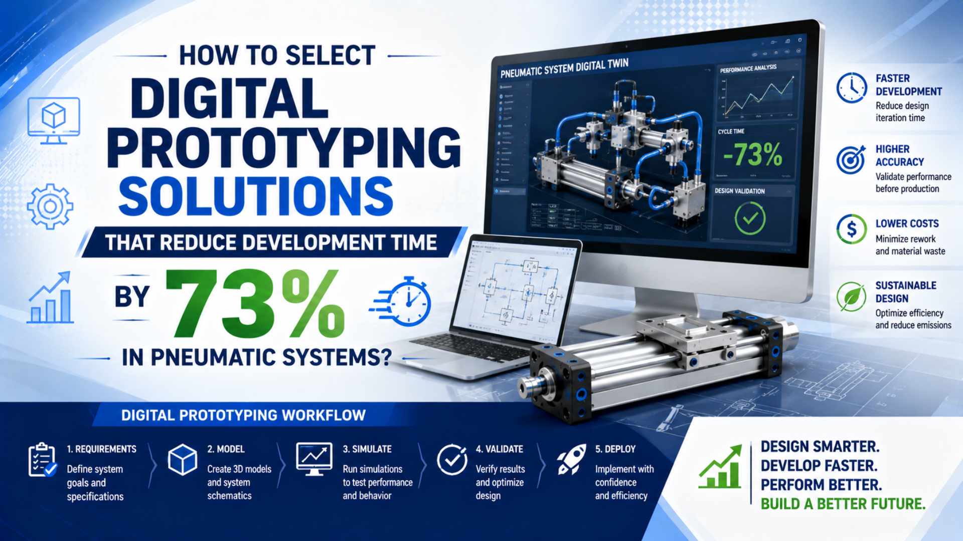
Digital prototyping solutions for pneumatic systems are software environments that let engineers test control logic, pneumatic behavior, or machine operation before relying on the complete physical machine. They can shorten a pneumatic automation project, but 73% is not a universal development-time guarantee. One published virtual-commissioning paper cited a potential 73% reduction in real commissioning time. That result concerned a particular project phase and modeling approach, not every pneumatic machine or the complete design-to-production schedule (Ghent University repository paper, retrieved 2026-07-27).
Select the solution by the decision it must support. PLC sequence testing, pneumatic pressure-and-motion prediction, and an operational digital twin are three different jobs. The winning platform is the one that models the required behavior, connects to the real controls, exposes its assumptions, and passes a representative pilot against measured hardware.
Key Takeaways
- A reported 73% benefit refers to potential real commissioning-time reduction, not guaranteed total development time.
- Separate virtual commissioning, pneumatic dynamic simulation, and operational digital-twin requirements.
- Validate pressure, flow, motion, timing, I/O, faults, and restart behavior against physical measurements.
- Use a paid pilot and written acceptance limits before committing to licenses, model libraries, or integration work.
What Does the 73% Reduction Actually Mean?
The 73% figure is a scope-limited virtual-commissioning benchmark. The cited paper says previous research found potential to reduce real commissioning time by 73% using a 3D digital model. It does not claim that pneumatic product design, component procurement, fabrication, installation, validation, and total project lead time all fall by that amount.
A Siemens industrial case shows why the baseline matters. Wipro PARI reported a 70% reduction in on-site commissioning, while the same case reported only a 5–10% reduction in delivery time and a 40–50% reduction in rework (Siemens Wipro PARI case study, retrieved 2026-07-27). These are different denominators.
Define the metric before evaluating software:
| Metric | Start event | End event | Evidence needed |
|---|---|---|---|
| PLC development time | First control-software task | Code ready for formal test | Time records and accepted test cases |
| Virtual commissioning time | Executable model available | Virtual acceptance complete | Model build effort plus test execution |
| On-site commissioning time | Installed equipment available | Site acceptance complete | Comparable project or controlled pilot baseline |
| Total project lead time | Approved requirements | Production release | Full schedule, including work shifted earlier |
| Rework | First released design | Final accepted machine | Change records classified by mechanical, electrical, controls, and pneumatic cause |
Virtual commissioning often moves work earlier instead of eliminating it. Model construction, I/O mapping, test-case authoring, and model maintenance consume engineering time. The business case should count those hours. Otherwise, a shorter site visit can hide an unchanged or longer total engineering effort.
The most defensible target is not “reduce development time by 73%.” It is “move a defined set of defects out of the site phase, then measure the change in site time, total engineering time, rework, and acceptance quality.” That wording prevents a local improvement from being presented as a project-wide saving.
Which Digital Prototyping Job Must the Solution Perform?
Digital prototyping for pneumatic automation usually covers three jobs: virtual commissioning, dynamic system simulation, or an operational digital twin. ISO 23247-2 provides a manufacturing digital-twin reference architecture, while FMI 3.0 defines three model interfaces: Model Exchange, Co-Simulation, and Scheduled Execution (ISO 23247-2; FMI 3.0.2, retrieved 2026-07-27).
| Job | Primary question | Minimum model behavior | Typical connection |
|---|---|---|---|
| Virtual commissioning | Does the control logic sequence correctly? | Actuator states, sensors, interlocks, timing, faults, material flow | Simulated PLC, real PLC, robot controller, HMI |
| Pneumatic dynamic simulation | Will pressure, flow, force, and motion meet the requirement? | Compressible volumes, valve flow, restrictions, friction, load, cushioning | Physics solver, controller model, parameter files |
| Operational digital twin | Does the virtual state remain useful after commissioning? | Asset identity, live data, configuration history, calibration, uncertainty | PLC/SCADA, historian, OPC UA, asset registry |
Don’t buy all three simply because a vendor uses the phrase “digital twin.” A sequence model can represent a cylinder as extended or retracted without predicting its stroke time. A detailed gas model can predict chamber pressure but may be too slow for real-time HIL. A live dashboard can synchronize tags while containing no predictive physics.
What Pneumatic Behavior Must the Model Represent?
ISO 6358-1 defines steady-state test methods for pneumatic components using compressible fluids. That matters because a model built from port threads and nominal supply pressure cannot predict cylinder timing. It needs usable flow characteristics, pressure boundaries, connected volumes, load data, and the operating conditions for the exact valve and actuator (ISO 6358-1, retrieved 2026-07-27).
Choose model fidelity from the decision:
| Required decision | Pneumatic behavior to include | Physical evidence |
|---|---|---|
| PLC sequence and collision logic | Commanded actuator states, end sensors, credible delays | I/O list, sequence specification, measured delay ranges |
| Stroke-time prediction | Chamber volumes, valve supply and exhaust flow, tube volume, pressure loss, load, friction, cushions | Valve flow data, cylinder dimensions, pressure traces, motion trace |
| Clamp-force screening | Effective piston area, minimum dynamic pressure, load direction, friction allowance | Controlled drawing, pressure measurement, force test |
| Synchronization review | Valve delay, pressure propagation, breakaway, sensor threshold, PLC scan and network update | Time-correlated command, pressure, position, and sensor records |
| Energy-loss or restart study | Valve fail state, trapped pressure, leakage, gravity or spring load, repressurization sequence | Circuit, risk assessment, pressure decay, restart movement |
| Operational drift monitoring | Versioned parameters, sensor quality, calibration state, environment, maintenance changes | Historian data, calibration records, change log |
The valve response-time consistency guide explains why one catalog response-time value is not a complete command-to-motion model. The specific-stroke-time valve-sizing guide covers the flow demand and installed restrictions that a dynamic model should reproduce.
A CAD model supplies geometry, mass properties, interfaces, and possible collision envelopes. It does not supply validated leakage, friction, cushioning, flow, switching delay, or seal-temperature behavior. Use the pneumatic cylinder CAD review checklist before treating supplier geometry as simulation-ready data.
Use the lowest fidelity that can answer the question
A state model can be enough to test whether the PLC commands extension before a guard condition is valid. It is not enough to approve a 300 ms stroke-time requirement. Conversely, a detailed three-dimensional flow model may add computation without improving a machine-level sequence decision.
Define the quantities of interest first. Examples include cylinder arrival time, peak chamber pressure, minimum clamp force, exhaust-decay time, timing skew, or maximum restart displacement. Then add model detail only when it materially changes one of those decisions.
Should You Use Software-in-the-Loop, Hardware-in-the-Loop, or Both?
Use SIL to test control software early and HIL to expose real controller timing, I/O behavior, and communication constraints. A hybrid program usually progresses through both. The virtual plant must run fast enough for the chosen connection, but “real time” should be defined against the controller task and required event timing, not a generic millisecond target.
| Architecture | Real control hardware | Best use | Main limitation |
|---|---|---|---|
| Model-in-the-loop | No | Model and algorithm development | Does not expose compiled control or hardware behavior |
| Software-in-the-loop | No | PLC logic, state sequencing, regression tests | Emulator timing and communications may differ from hardware |
| Hardware-in-the-loop | Yes | Real PLC tasking, I/O, network, HMI, fault and restart tests | Requires deterministic execution and safe electrical integration |
| Physical bench correlation | Partial system | Parameter identification and model validation | Covers only the tested configuration and range |
| Full-machine validation | Yes | Final acceptance and safety validation | Occurs later and is more expensive to change |
SIL is usually the economical first gate. It supports repeatable automated tests before the controller cabinet is available. HIL becomes valuable when the decision depends on actual controller scan behavior, communication adapters, task priority, safety-controller interfaces, physical I/O, or vendor firmware.
Virtual time scaling is useful for long sequences and regression tests, but it cannot prove real-time performance. Record wall-clock execution, missed deadlines, communication-step size, jitter, and solver overruns during HIL. If the model falls behind, define whether the platform slows the controller, drops updates, extrapolates values, or fails the test.
Which Interfaces and Data Standards Matter?
FMI 3.0.2 defines Model Exchange, Co-Simulation, and Scheduled Execution, while OPC UA Companion Specifications define reusable information models for domain-specific interoperability. These standards solve different problems: FMI packages executable models and their interfaces; OPC UA organizes discoverable machine information and services (FMI; OPC Foundation, retrieved 2026-07-27).
Check six interface layers:
- Geometry exchange: native CAD, STEP, JT, kinematic joints, coordinate systems, configuration identity, and revision.
- Behavior-model exchange: FMU version, supported FMI interface type, solver ownership, variable units, events, and parameter protection.
- Controller connection: supported PLCs, emulators, real controllers, safety PLC restrictions, cycle-time behavior, and licensing.
- Signal mapping: naming, data types, scaling, units, default values, quality state, missing signals, and automated diff capability.
- Machine information: OPC UA information model, alarms, states, historical data, security, and companion-specification compatibility.
- Evidence export: test definitions, logs, time synchronization, model version, controller version, result comparison, and audit trail.
IEEE Time-Sensitive Networking can provide bounded network behavior in an appropriate architecture, but it is not a universal virtual-commissioning protocol. It does not replace the model interface, semantic signal definition, controller adapter, or test harness.
Ask each supplier to demonstrate one export and one re-import. A slide claiming “FMI support” is insufficient if the pneumatic solver can export only static parameters or if the receiving tool silently changes units, events, interpolation, or solver assumptions.
Interoperability should be tested as a round trip, not a checkbox. Export the selected cylinder-and-valve subsystem, import it into the target co-simulation environment, change one controlled parameter, run the same test, and confirm that identity, units, events, and numerical results remain traceable.
How Should Pneumatic Model Verification and Validation Be Structured?
NIST states that digital-twin credibility requires verification, validation, and uncertainty quantification throughout the lifecycle. ASME V&V 20 similarly frames validation as comparing a specified simulation variable with experiment at a specified validation point while accounting for uncertainty in both solution and data (NIST; ASME V&V 20, retrieved 2026-07-27).
Keep four activities separate:
- Code verification: Is the mathematical problem solved correctly by the implementation?
- Calculation verification: Are mesh, time step, solver tolerance, events, and numerical convergence adequate for this run?
- Validation: Does the model agree with physical measurements closely enough for its intended decision?
- Uncertainty quantification: How do parameter, measurement, numerical, and model-form uncertainty affect the conclusion?
Build a validation matrix instead of publishing one overall “accuracy” percentage:
| Quantity of interest | Test condition | Comparison | Acceptance form |
|---|---|---|---|
| Cylinder stroke time | Minimum dynamic supply, defined load and flow controls | Simulated and measured arrival time | Maximum absolute or relative error |
| Chamber pressure | Command step in both directions | Time-correlated pressure traces | Error band and timing offset |
| Breakaway delay | Defined rest time, temperature, and load | Command-to-first-motion delay | Maximum and repeatability |
| End cushioning | Defined speed, mass, and cushion setting | Pressure peak and end velocity | Limit for peak and residual motion |
| Sensor event | Real switch position and PLC input | Physical position and event timestamp | Position and time tolerance |
| Supply or pilot loss | Defined initial state and load | Pressure decay and actuator movement | Maximum residual pressure and displacement |
Validation is local to a configuration and operating range. Agreement at one pressure, temperature, load, or direction does not prove the model everywhere. Record the validated envelope and flag extrapolation outside it.
The pneumatic position-sensing guide helps define which events can be observed with end switches and which require continuous position feedback. Model validation cannot be more precise than the physical measurement system.
What Timing and Fault Tests Must a Virtual Commissioning Pilot Pass?
The Siemens Wipro PARI project modeled four robots, 10 machining centers, more than 100 conveyors and related devices, and 17 product variants. That scale required zoning, HIL, robot integration, and explicit safety-interlock tests, not a single animation run (Siemens case study, retrieved 2026-07-27).
For a pneumatic pilot cell, test at least:
- normal extension and retraction from each valid starting state;
- minimum and maximum credible supply pressure;
- slow valve, delayed sensor, stuck sensor, and contradictory signal;
- flow restriction, blocked silencer, pressure loss, and pilot-pressure loss;
- manual override and maintenance mode;
- electrical power loss and controller restart;
- main-air isolation, pressure decay, and repressurization;
- rejected part, jammed mechanism, and interrupted cycle;
- product changeover and recipe mismatch;
- recovery from each injected fault without bypassing the intended interlock.
The ISO 1219 valve-symbol guide helps keep simulated port states aligned with the actual circuit. A component labeled “5/2 valve” is incomplete unless normal position, return method, pilot source, flow path, and loss-of-energy behavior also match.
Timing acceptance should put controller commands, simulated valve state, pressure, actuator position, sensor state, and fault code on one time base. That trace distinguishes a logic defect from a model delay, pneumatic restriction, sensor threshold, or communication problem.
In our experience, the quickest way to expose a weak virtual prototype is to start a cycle from an abnormal but physically possible state. A model that succeeds only from its preferred home position is useful for demonstrations, not commissioning.
How Should Safety Claims Be Handled?
ISO 4414 addresses significant hazards in pneumatic systems and applies to system design, installation, adjustment, operation, and maintenance. Virtual testing can improve coverage, but it does not replace physical confirmation of load restraint, residual energy, pressure decay, stopping performance, guarding, or the complete machine safety function (ISO 4414, retrieved 2026-07-27).
Keep safety-related uses inside a controlled evidence chain:
- Define the safety function and required machine state from the risk assessment.
- Identify which controller, valve, actuator, restraint, sensor, exhaust path, and reset behavior contribute.
- Use the virtual model to exercise sequences, combinations, and diagnostic coverage.
- Mark every idealized or unmodeled physical behavior.
- Confirm component data and circuit behavior on hardware.
- Validate the installed safety function using the applicable machinery-safety process.
A virtual closed-center valve may show zero cylinder motion because the model assumes zero leakage. The physical valve and cylinder may drift. An exhaust command may appear to remove pressure instantly while a real meter-out valve, pilot check, silencer, or long tube retains energy. The model must not turn missing physics into a safety claim.
How Should You Run a Paid Pilot Before Buying?
A useful pilot contains one representative pneumatic station, one real engineering decision, and written pass/fail limits. NIST’s digital-twin program emphasizes testbeds, validation, interoperability, quantified uncertainty, and traceable results rather than accepting the label “digital twin” as evidence (NIST Digital Twins for Advanced Manufacturing, retrieved 2026-07-27).
Use this pilot sequence:
- Freeze the controlled circuit, I/O list, component revisions, operating range, and quantities of interest.
- Record the current workflow baseline: engineering hours, site hours, defects, rework, and acceptance outcome.
- Build the smallest model that supports the chosen decision.
- Connect the actual PLC or approved emulator and import the production control program.
- Run normal, boundary, fault, power-loss, and restart tests.
- Correlate the model with measured pressure, motion, and event timing.
- Change one valve, cylinder, tube, sensor, or controller parameter and repeat.
- Export the model, test definitions, logs, and results; then verify that another engineer can reproduce them.
- Measure model-build and maintenance effort as well as time saved.
- Approve expansion only when every written gate passes.
What Must Be Included in the Software RFQ?
An effective RFQ separates required capability from optional demonstrations. Specify one pilot model, three evidence layers, and explicit ownership: the model must answer the engineering question, reproduce the required control interface, and export enough data for independent review. Avoid scoring a platform by the length of its feature list.
| RFQ field | Required supplier response |
|---|---|
| Intended use | Virtual commissioning, pneumatic dynamics, operational twin, or defined combination |
| Pneumatic scope | Valves, cylinders, lines, restrictions, leakage, friction, cushioning, sensors, loads |
| Controller scope | Supported PLCs, emulators, real hardware, robots, HMI, safety restrictions |
| Real-time behavior | Supported step size, overrun handling, time scaling, logging, synchronization |
| Interoperability | CAD formats, FMI version and interface type, OPC UA model, APIs, signal mapping |
| Validation | Quantity-specific error metrics, test range, uncertainty, extrapolation warning |
| Fault testing | Sensor, valve, supply, pilot, communication, power, restart, jam conditions |
| Configuration control | Model identity, component revision, parameter source, branching, audit history |
| Data governance | Storage, retention, access, encryption, IP protection, offline operation |
| Automation | Test scripting, regression execution, comparison reports, CI integration |
| Commercial model | Authoring, runtime, HIL, connector, solver, cloud, and support licenses |
| Handoff | Training, model ownership, reusable library rights, export, support response |
| Pilot acceptance | Named station, schedule, deliverables, measurements, pass/fail limits |
Require the supplier to state what is not modeled. Useful limitations include zero leakage, ideal valves, fixed friction, simplified exhaust behavior, rigid tubing, no thermal coupling, or unsupported safety-controller behavior. Hidden simplifications are more dangerous than modest, explicit model scope.
The final selection should record a disposition for every RFQ requirement: pass, conditional pass, failed, or not applicable. Capture the exact software build, solver, connector, PLC firmware, component library, and model revision used in the pilot.
Digital Prototyping for Pneumatic Systems FAQs
Does virtual commissioning really reduce development time by 73%?
It can reduce a defined commissioning phase substantially, but 73% is not a universal result. The published figure concerns potential real commissioning-time reduction with a particular 3D virtual-commissioning approach. Establish your own baseline and count model-building, integration, test authoring, site work, rework, and total lead time separately.
Is a 3D CAD model enough for pneumatic virtual commissioning?
No. CAD provides geometry and possible kinematics, but pneumatic behavior also depends on valve function and flow, chamber and tube volume, pressure loss, load, friction, cushioning, sensor thresholds, leakage, and controller timing. Use a state model for logic tests or a validated dynamic model when pressure and motion matter.
What is the difference between SIL and HIL?
Software-in-the-loop runs the control software or an emulator without the production controller hardware. Hardware-in-the-loop connects the virtual plant to the real controller and exposes actual tasking, I/O, communications, firmware, and timing behavior. Most projects should use SIL first, then reserve HIL for hardware-dependent risks.
Can an operational digital twin stay accurate automatically?
No. A useful twin needs controlled model and asset identity, reliable sensor data, calibration, parameter governance, change detection, validation limits, and uncertainty reporting. Component replacement, tuning changes, wear, sensor drift, software revisions, or changed operating conditions can invalidate predictions even when live tags continue updating.
Can virtual testing replace physical pneumatic safety validation?
No. Virtual testing can improve fault coverage and find sequence defects early, but it cannot prove actual leakage, residual pressure, load restraint, stopping performance, exhaust behavior, guarding, or installed safety integrity. Use it as one layer in the evidence chain, followed by hardware and machine-level validation.
Sources and Technical References
Ghent University and Flanders Make: Virtual Commissioning of Industrial Control Systems: A 3D Digital Model Approach, scope and context of the reported 73% potential reduction in real commissioning time. Retrieved 2026-07-27.
Siemens Digital Industries Software: Wipro PARI virtual commissioning case study, project scope and separately reported on-site commissioning, delivery-time, and rework results. Retrieved 2026-07-27.
NIST: Digital Twins for Advanced Manufacturing, standards, testbeds, interoperability, VVUQ, and trustworthy manufacturing digital twins. Retrieved 2026-07-27.
NIST: Credibility Consideration for Digital Twins in Manufacturing, verification, validation, uncertainty quantification, and lifecycle credibility. Retrieved 2026-07-27.
ISO: ISO 23247-2:2021, manufacturing digital-twin reference architecture. Retrieved 2026-07-27.
Modelica Association Project: FMI 3.0.2 specification, Model Exchange, Co-Simulation, and Scheduled Execution interfaces. Retrieved 2026-07-27.
OPC Foundation: OPC UA Companion Specifications, domain-specific information models and OPC UA interoperability. Retrieved 2026-07-27.
ASME: V&V 20, validation comparison and uncertainty for computational fluid dynamics and heat transfer. Retrieved 2026-07-27.
ISO: ISO 6358-1:2013, steady-state flow-rate characterization of pneumatic components using compressible fluids. Retrieved 2026-07-27.
ISO: ISO 4414:2010, general rules and safety requirements for pneumatic systems and components. Retrieved 2026-07-27.