

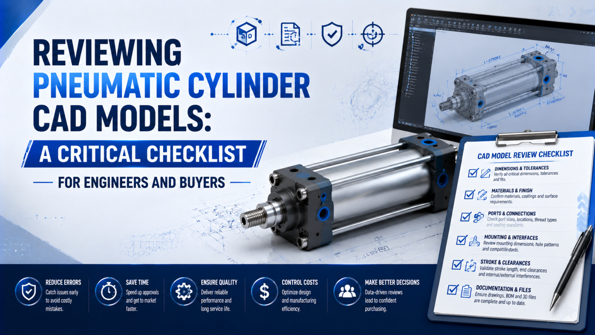
A pneumatic cylinder CAD review should answer a narrow but important question: will the exact configured component fit, move, connect, and remain serviceable in the machine? It should not be used to approve pressure rating, seal compatibility, life, or manufacturing tolerances unless those requirements are included as controlled product-definition data.
That distinction prevents a common approval error. A clean STEP model can describe the correct outside shape while still carrying the wrong revision, omitting an accessory, losing product and manufacturing information, or failing to represent the hose, cable, and tool space needed after installation.
Key Takeaways
- ISO 15552 covers detachable-mount cylinders from 32 to 320 mm bore at up to 10 bar (ISO 15552:2018).
- Review static, swept, and service envelopes separately.
- Approve the model only with its part number, revision, controlled drawing or PMI, technical data, and recorded disposition.
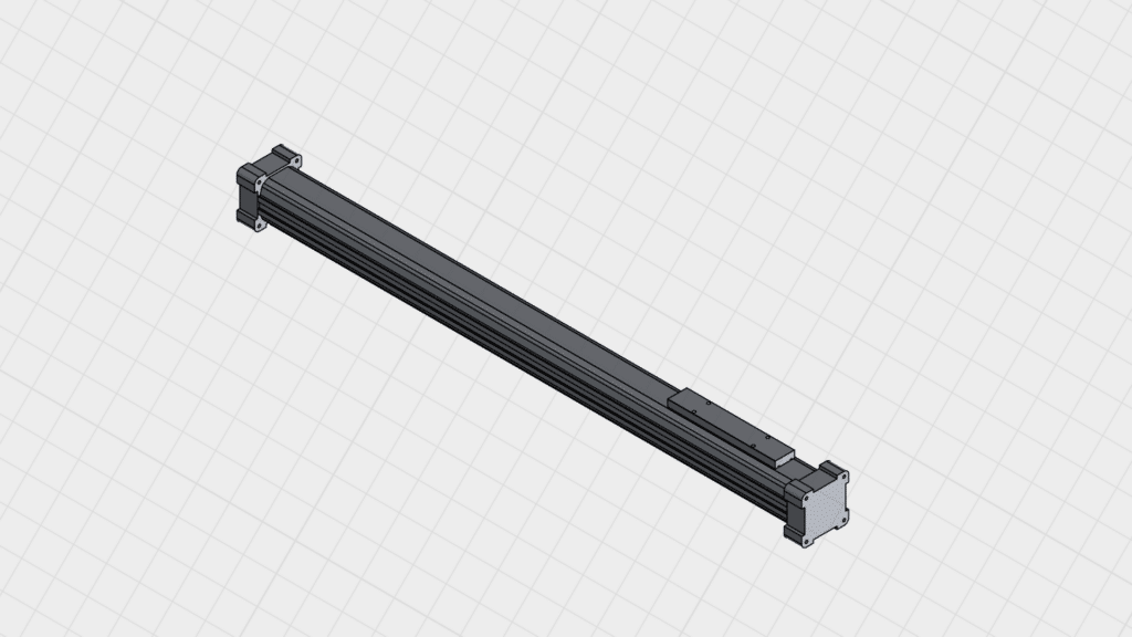
A supplier CAD model is useful reference geometry, but approval still depends on controlled configuration and product evidence.
CAD reference geometry is the component shape and nominal interface data needed for assembly work.
Product definition data is the controlled set of dimensions, tolerances, datums, notes, materials, finishes, and revision information that specifies the product.
Approval disposition is the recorded decision that accepts, rejects, or conditionally accepts the submitted configuration.
A CAD Model Is Reference Geometry, Not the Product Specification
ISO 16792:2021 is a 76-page, third-edition standard that supports two digital product-definition methods: a 3D model alone or a 3D model with a 2D drawing. That scope makes the governing data set explicit; an unannotated solid by itself cannot be assumed to contain every manufacturing or acceptance requirement (ISO 16792:2021).
For most supplier cylinders, the practical review package has several authorities. The assembly model controls fit analysis. A dimensioned drawing or semantic PMI controls specified dimensions and tolerances. The catalog or data sheet controls rated performance. Certificates and inspection records show what was supplied and verified.
Treating those files as one interchangeable source creates silent conflicts. If the STEP model says one thing and the released drawing says another, the review should stop. The discrepancy needs a documented supplier response and a new revision, not an engineer’s guess about which file looks more plausible.
How Do You Confirm File Identity, Revision, and Coordinate System?
ISO 10303-242:2025 is the 64-page, fourth edition of AP242. Its scope includes configuration control, version tracking, release and approval data, product documentation, mating information, and kinematics. Those capabilities explain what a managed exchange can contain, but the reviewer must still confirm what the supplier actually included (ISO 10303-242:2025).
Start with a submission manifest before measuring geometry:
| Identity field | Review question | Required evidence |
|---|---|---|
| Supplier and family | Who owns the model, and which cylinder family is represented? | Supplier name and product family |
| Complete part number | Are bore, stroke, ports, mounts, cushions, sensors, and seal options encoded? | Order code breakdown |
| Revision and date | Does the model match the released drawing and quotation? | Revision identifier and release date |
| File format | Is the file native CAD, STEP AP242, another STEP application protocol, or a visualization mesh? | Format and export settings |
| Units | Was the model authored and imported in the intended length unit? | Declared unit plus a known dimension check |
| Origin and axes | Which planes define mounting, stroke direction, and home position? | Coordinate-system note |
| Configuration state | Which carriage or rod position and accessory combination are shown? | Saved configuration description |
A practical rule from our application reviews is to pause geometry approval when the complete part number or revision is missing. Measuring an unidentified model creates precise results for an unknown configuration.
A filename such as cylinder-final.step is not configuration control. A useful name ties the file to the exact part number and revision, while the transmittal records who issued it and which earlier file it replaces.
What if the assembly uses the correct shape at the wrong origin? Mates can hide the problem until someone replaces or regenerates the component. Verify the mounting datum, stroke axis, port orientation, and defined home position before building downstream constraints.
How Should a STEP File Be Validated After Translation?
NIST’s STEP File Analyzer and Viewer version 5.41 checks four distinct areas: entity data, semantic PMI, graphic PMI, and basic file syntax. It also reads validation properties used to compare translated geometry, so a successful import is only the start of verification (NIST STEP File Analyzer and Viewer, updated 2025).
The receiving engineer should perform these checks:
- Open the file without repair warnings, unresolved references, or missing bodies.
- Compare a known overall dimension and one interface dimension with the released drawing.
- Compare body count, assembly structure, and component names with the supplier manifest.
- Inspect area, volume, and centroid validation properties when the exchange contains them.
- Confirm whether tolerances are semantic PMI, graphic annotations, or absent.
- Recheck units, orientation, and saved configuration after import.
NIST distinguishes semantic PMI from graphic PMI. Semantic PMI is machine-interpretable and can support downstream manufacturing and inspection. Graphic PMI preserves the visual appearance of annotations but doesn’t carry the same representation information. A reviewer who sees tolerance symbols on screen still needs to know which kind arrived.
Don’t approve a repaired import without recording the repair. If the CAD system changes faces, closes gaps, removes small features, or substitutes a simplified body, request a new export or obtain written agreement that the repaired geometry is acceptable for the intended review.
Which Cylinder Interfaces Must Be Checked Against Controlled Drawings?
ISO 15552:2018 covers detachable-mount pneumatic cylinders from 32 to 320 mm bore at a maximum rated pressure of 1,000 kPa, or 10 bar. Its 18 pages standardize selected basic, mounting, and accessory dimensions for interchangeability, not every port, sensor, seal, cushion, or performance option (ISO 15552:2018, confirmed 2025).
That scope is a useful warning: even a standard-family cylinder needs an option-specific drawing. Use the CAD model to place the component, then verify each controlled interface against the drawing, catalog, and order code.
| Interface | Use the CAD model to check | Use controlled evidence to confirm |
|---|---|---|
| Mounting face | Contact area and access | Hole locations, thread designation, depth, datums, and tolerances |
| Rod or carriage connection | Nominal alignment and tool position | Thread, pilot, key, hole pattern, allowable load, and moment limits |
| Air ports | Orientation and fitting envelope | Thread standard, port size, sealing method, alternate-port rules, and rated pressure |
| Sensors | Slot position and cable exit | Compatible sensor model, switching function, electrical data, and mounting hardware |
| Cushions and adjusters | Access and protrusion | Adjustment method, setting instructions, and permitted operating range |
| Mounting accessories | Assembly location and pivot sweep | Exact accessory code, pin or bolt dimensions, and permitted articulation |
Thread labels deserve special attention. G1/4, R1/4, and 1/4 NPT are not interchangeable descriptions. When supplier and machine documents use different conventions, resolve the sealing method and mating part before approval. The BSP, NPT, G, and R thread guide provides a focused comparison.
For an ISO-family replacement, also use the ISO 15552 interchangeability checklist. A standard reference reduces the comparison set, but it doesn’t prove that two complete configurations are drop-in equivalents.
How Should Static, Swept, and Service Envelopes Be Reviewed?
Autodesk Inventor 2026 can analyze assembly interference and report the volume and centroid of detected overlaps. That is useful for the installed state, but one static calculation cannot prove a pneumatic cylinder is clear throughout motion, adjustment, hose movement, and maintenance (Autodesk Inventor, Check for Interference).
Review three envelopes, each with its own acceptance rule:
Static envelope: Load the exact cylinder, mount, sensor, connector, fitting, silencer, and adjuster configuration. Check all fixed machine states that can change orientation or proximity.
Swept envelope: Move the rod, carriage, attached tooling, pivoting mount, cable loop, and hose through the full intended range. Include homing, setup, fault recovery, and any manual movement that can occur with energy isolated.
Service envelope: Reserve room to connect tubing, tighten fittings, adjust cushions, replace sensors, remove fasteners, withdraw pins, and extract the cylinder. Otherwise, a collision-free installation can still be unserviceable.
In our application reviews, service access is the check most likely to change a seemingly acceptable mounting orientation. The cylinder may fit, yet the only removal path can remain blocked by a frame member, cable tray, or guard.
There is no universal installation-clearance rule. Set clearance from the worst-case tolerance stack, structural deflection, expected vibration, thermal movement, hose and cable minimum bend radii, guarding, and the tool path required by the maintenance plan.
What Must Be Cross-Checked Outside the CAD Model?
ISO 1101:2017 is the current 145-page, fourth edition defining the symbol language and interpretation rules for geometrical tolerancing. It also permits specifications to be attached to a 3D model under ISO 16792, which means the reviewer must identify the controlled annotation method rather than infer tolerances from nominal geometry (ISO 1101:2017).
Cross-check these evidence groups:
| Requirement | Why CAD geometry is insufficient | Evidence to approve |
|---|---|---|
| Dimensions and tolerances | Nominal faces don’t state allowable variation or datum relationships | Released drawing or controlled semantic PMI |
| Materials and finishes | Appearance and generic CAD properties don’t prove supplied grade or treatment | Data sheet, order code, material or coating certificate when required |
| Pressure and environment | Shape doesn’t establish pressure rating, temperature derating, media compatibility, or ingress protection | Option-specific technical data and declarations |
| Force, speed, and cushioning | Bore and stroke alone don’t capture dynamic pressure, friction, back pressure, flow, load, or stopping energy | Application calculation, catalog limits, and machine test |
| Side load and moment | External geometry doesn’t reveal bearing design or allowable load curves | Manufacturer load and moment data |
| Safety behavior | A model doesn’t show stored-energy controls, exhaust strategy, fault response, or safe restart | Circuit, risk assessment, instructions, and validation plan |
Theoretical force deserves special care. Geometry can support a piston-area calculation, but usable force depends on effective chamber pressure and losses. Use the effective piston area guide for the calculation, then confirm the result against measured or specified application conditions.
Speed and cushioning are also system properties. Valve flow, tubing, fittings, exhaust restriction, moving mass, orientation, and end-of-stroke energy all matter. The high-speed pneumatic cylinder checklist explains those dependencies.
What about guide loads? A carriage that fits the mounting pattern can still be overloaded by an offset center of mass. Review the supplier’s load and moment diagrams, then compare them with the machine free-body model. The cylinder side-loading guide covers the resulting bearing and seal risks.
Configuration Control and Approval Disposition
ISO 10303-242:2025, edition 4, includes product version management, change history, release and approval data, quality criteria, inspection results, mating information, and kinematics. A sound review record mirrors those controls even when the supplier sends ordinary STEP files and PDFs instead of a managed AP242 data set (ISO 10303-242:2025).
Record the approval against a package, not a loose file. The package identifier should connect the CAD model, controlled drawing or PMI, data sheet, supplier quotation, deviations, and review report. If one item changes, the package returns to review at the affected checkpoints.
A practical disposition record contains:
- exact part number and option code;
- CAD filename, format, revision, checksum, and receipt date;
- drawing or PMI identifier and revision;
- machine assembly revision used for the check;
- scenarios reviewed, including motion and service states;
- unresolved assumptions and accepted deviations;
- names, roles, dates, and decision status;
- supplier responses and superseded-file references.
Use three clear statuses: approved, approved with conditions, or rejected. “Looks good” isn’t actionable. A conditional approval should name the open item, its owner, the evidence required, and the event that blocks purchase or machine release until closure.
Change impact should follow requirement ownership. A revised fitting may trigger a static and service-envelope review but not a new material assessment. A seal-option change may leave geometry untouched while reopening temperature, media, friction, and lubrication checks. This keeps re-review focused without treating an unchanged shape as proof of an unchanged product.
Procurement Release Checklist
ISO 4414:2010 is a 38-page, third-edition standard covering pneumatic-system design, construction, modification, assembly, installation, adjustment, maintenance, reliable intended use, energy efficiency, and environmental concerns. Procurement therefore needs evidence for the installed function, not only a CAD fit approval (ISO 4414:2010, confirmed 2021).
Before releasing an order, confirm that the supplier returned:
- the complete and orderable cylinder part number;
- native CAD when useful, plus a declared neutral exchange format;
- the released dimensional drawing or controlled model-based definition;
- bore, stroke, mounting, rod or carriage interface, port, cushion, sensor, seal, and accessory options;
- rated pressure, temperature range, media requirements, speed limits, load limits, and cushioning data applicable to that configuration;
- installation, adjustment, maintenance, and safety instructions;
- requested certificates, declarations, inspection records, and acceptance-test commitments;
- revision-control and change-notification terms;
- written closure of every deviation from the RFQ.
Use the ISO 15552 procurement checklist when the cylinder belongs to that dimensional family. If a mounting arrangement is being changed to gain flexibility, compare the structural and alignment consequences with the multi-mount actuator guide.
Can CAD review reduce cost? Yes, by finding interference, unnecessary custom interfaces, and service problems before release. But cost comparisons need normalized specifications and supplier quotations. A model does not prove two cylinders have equal life, equal performance, or a particular percentage saving.
Pneumatic Cylinder CAD Review FAQs: What Should Engineers Ask?
ISO 16792:2021 provides two recognized digital product-definition methods across 76 pages, while ISO 10303-242:2025 adds managed configuration, approval, PMI, and kinematic capabilities. The right question depends on what the supplier delivered and which file controls each requirement (ISO 16792; ISO 10303-242).
Is a STEP file enough to approve a pneumatic cylinder?
No. A STEP file can support geometry exchange and may contain PMI, configuration, or validation data, but content varies by export. Approve it with the exact part number, revision, controlled drawing or model-based definition, technical data, and application evidence. NIST recommends checking STEP syntax, PMI, and validation properties after translation.
Should the 3D model or the 2D drawing control dimensions?
Use the document identified by the supplier’s product-definition and configuration-control process. ISO 16792 supports model-only and model-plus-drawing methods, so there isn’t one universal answer. When a conventional drawing is the released authority, don’t override its dimensions or tolerances with measurements taken from nominal CAD geometry.
What accessories must appear in the CAD assembly?
Include every item that changes fit, movement, access, or routing: mounts, rod-end or carriage hardware, sensors, connectors, cables, fittings, silencers, cushion adjusters, flow controls, and attached tooling. A simplified model can remain useful, but its omitted items and intended review scope must be stated.
How much installation clearance should be added around a cylinder?
There is no universal clearance value. Build it from tolerance accumulation, structural movement, vibration, thermal effects, hose and cable bend limits, guarding, adjustment access, tool access, and removal paths. Record the accepted minimum for each interference pair rather than applying one arbitrary distance around the entire cylinder.
When must a previously approved CAD model be reviewed again?
Re-review it when the supplier part number, revision, option, drawing, model, accessory, or adjacent machine geometry changes. Limit the repeat review to affected requirements only after documenting the change impact. An unchanged external envelope doesn’t close material, seal, rating, or performance changes that leave geometry untouched.
Sources and technical references
- ISO 16792:2021, Digital product definition data practices
- ISO 10303-242:2025, AP242 managed model-based 3D engineering
- ISO 1101:2017, Geometrical tolerancing
- ISO 15552:2018, Detachable-mount pneumatic cylinder dimensions
- ISO 4414:2010, Pneumatic-system rules and safety requirements
- NIST STEP File Analyzer and Viewer
- Autodesk Inventor 2026, Check for Interference