

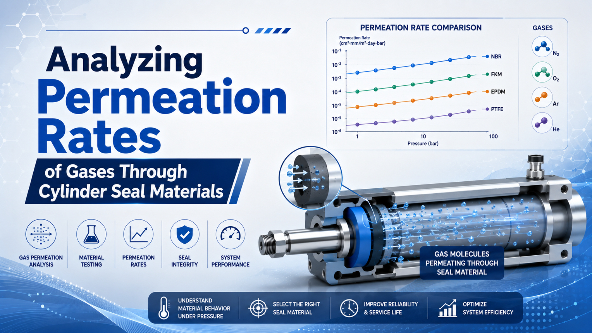
Gas permeation is the movement of gas through an intact polymer, not around a damaged sealing edge. It can matter in long hold periods, vacuum service, analytical equipment, and specialty-gas systems. In ordinary plant pneumatics, however, a fitting leak, valve path, scratched surface, or piston bypass often dominates the measured loss.
That distinction changes the investigation. A polymer-family name such as NBR, FKM, TPU, or PTFE doesn’t provide a finished-cylinder leak rate. Engineers need the gas, exact compound, temperature, pressure difference, seal geometry, squeeze, lubrication state, hardware condition, and measurement boundary before a permeation estimate becomes useful.
Key Takeaways
- Parker’s O-ring estimate uses 5 inputs to calculate an approximate loss rate.
- Compare permeability data only at matched gas, compound, temperature, units, and method.
- A pressure-hold test measures total loss; it doesn’t identify permeation by curve shape alone.
- ASTM D1434 and ISO 15105 test films or sheets, not complete cylinder seals.
What Is Gas Permeation, and How Is It Different From Leakage?
Parker’s handbook provides permeability tables for 4 gases: hydrogen, nitrogen, helium, and carbon dioxide. It defines permeation as pressurized gas entering an elastomer and escaping at the non-pressurized side, while also showing that total seal loss can include gas migration through incompletely filled surface irregularities (Parker O-Ring Handbook, 2024).
Gas permeation is transport through the bulk sealing material. In the common solution-diffusion description, molecules first dissolve into the high-pressure surface, diffuse through the polymer matrix, and desorb at the low-pressure surface. The permeability coefficient combines the material’s gas solubility and diffusivity:
Here, is permeability for one gas-material-temperature condition, is the diffusion coefficient, and is the solubility coefficient. These quantities are condition-specific. A value for dry nitrogen at 20°C doesn’t become an air, helium, hydrogen, or hot-service value by changing the label.
Mechanical leakage follows a physical path around the seal or through the assembly. That path may be a scratch, extrusion damage, an incorrect groove, poor surface contact, a port fitting, a valve seat, or piston bypass. Replacing a sound seal compound won’t close a leaking fitting, and tightening a fitting won’t change diffusion through an intact elastomer.
The two mechanisms can occur together. Surface roughness and incomplete contact are especially awkward because their gas path lies at the seal interface, yet it isn’t bulk permeation. This is why a system pressure gauge alone can’t assign the loss to one mechanism.
For component identification, start with the industrial cylinder seal types guide. If the suspected path crosses the piston from one chamber to the other, use the separate pneumatic cylinder internal leakage procedure.
Three Gas-Transmission Quantities Must Not Be Mixed
ASTM D1434 distinguishes 3 reported quantities: gas transmission rate, permeance, and permeability. The distinction matters because only permeability normalizes a suitable homogeneous specimen result for thickness, while a rate per area and pressure is not automatically a material constant (ASTM D1434-23, 2023).
Gas transmission rate, or GTR, reports how much test gas crosses a specimen area per unit time under specified conditions. It belongs to the tested specimen. Change thickness, morphology, temperature, humidity, or pressure conditions and the reported rate can change.
Permeance divides transmission by the driving pressure difference. It still belongs to the specimen configuration. A value in is a permeance-style quantity because thickness isn’t present in the units.
Permeability adds a length term and is intended to characterize a homogeneous material when the thickness relationship is valid. For a flat specimen at steady state, the screening relationship is:
Here, is gas flux, is the gas permeability coefficient, is the partial-pressure difference for the test gas, and is specimen thickness. This equation describes a planar, homogeneous path. A compressed O-ring, energized PTFE seal, U-cup, or rodless-cylinder band needs geometry appropriate to its actual shape.
ASTM warns against converting a transmission result into a permeability coefficient unless the thickness-to-transmission relationship is already known. It also identifies plasticizer content, nonhomogeneity, moisture, procedure, and laboratory as sources of variation. Those cautions rule out copying unmatched supplier values into one universal material table.
How Can Parker’s O-Ring Model Estimate Permeation?
Parker’s O-ring approximation uses 5 inputs: permeability coefficient, O-ring inside diameter, differential pressure, a squeeze-and-lubrication correction factor, and cross-section compression. These inputs produce an approximate loss rate. Parker also states that the result is rough because compounds within one polymer family can differ (Parker O-Ring Handbook, 2024).
Using Parker’s published notation, the approximation is:
In this equation:
- is approximate gas loss in ;
- is Parker’s tabulated permeability coefficient in the handbook’s stated units;
- is O-ring inside diameter in millimetres;
- is differential pressure in bar;
- is Parker’s correction factor for compression and lubrication;
- is cross-section compression expressed as a decimal.
Use the formula only with the units and coefficient definition published beside Parker’s tables. Don’t insert a value reported per square centimetre per day and assume it is the same . A dimensionally different number can produce a plausible-looking but meaningless result.
The equation also carries 3 geometric assumptions: the deformed cross-section is rectangular, the compressed and uncompressed cross-sectional areas are equal, and gas permeability is proportional to differential pressure. That makes it a screening estimate for an O-ring, not a certification method for every cylinder seal.
The most useful output is often an order-of-magnitude check. If the calculated permeation is far below the measured total loss, investigate interfaces, valves, tubing, ports, piston bypass, and temperature effects first. If the estimate approaches the measured loss, commission a compound-specific fixture test before changing the actuator design.
Why Doesn’t Polymer Family Create a Universal Ranking?
Parker’s nitrogen table lists TPU at 0.17 at 23°C, NBR at 0.5 at 20°C, and FKM at 0.25 at 30°C in the handbook’s coefficient scale. Even this small set uses 3 temperatures, so it cannot support an unconditional TPU-versus-NBR-versus-FKM ranking (Parker O-Ring Handbook, 2024).
A base-polymer name hides the formulation. Fillers, plasticizers, cure chemistry, hardness, processing history, crystallinity, and absorbed media can all change transport behavior. Two NBR compounds may share a label while delivering different permeability, compression set, wear, low-temperature response, and chemical compatibility.
Gas identity matters as much as polymer family. Permeation depends on both molecular diffusion and solubility in the material. Smaller molecules often diffuse quickly, but high solubility can make a larger gas permeate more strongly than a simple molecular-size ranking predicts. Carbon dioxide is the usual warning against treating size as the only variable.
PTFE needs the same discipline. Virgin PTFE, modified PTFE, filled PTFE, and an elastomer-energized PTFE seal aren’t one interchangeable product. A low coupon permeability doesn’t prove that the complete seal has adequate contact stress, acceptable cold flow, low interface leakage, or suitable dynamic wear.
For broader selection by media, motion, temperature, and hardware, use the pneumatic cylinder seal material guide. Permeation should be one evidence column in that review, not the sole selection criterion.
Gas and Temperature Change the Result
Parker’s NBR nitrogen coefficient rises from 0.5 at 20°C to 14 at 80°C, a 28-fold difference in the published table. For helium, NBR rises from 8 at 25°C to 66 at 80°C. These values show why room-temperature air data cannot validate a hot helium application (Parker O-Ring Handbook, 2024).
Temperature changes diffusion, solubility, seal squeeze, lubricant viscosity, and hardware dimensions at the same time. An Arrhenius relationship may fit a compound over a validated temperature interval, but a generic “doubles every 20°C” rule isn’t a substitute for measured data. Extrapolation can cross material transitions and create large errors.
Pressure requires similar care. A steady-state model may assume permeability proportional to differential pressure, yet the gas concentration inside the material needs time to approach equilibrium. The initial transient, soak duration, pressure history, and decompression rate can matter, especially with thick sections or high-pressure gas.
Rapid decompression is a different failure question. Gas absorbed in an elastomer can expand faster than it escapes, producing blisters, cracks, or pits. Parker calls this explosive decompression and evaluates it using gas, pressure, compound, section size, and decompression conditions. A compound with low permeation isn’t automatically the best rapid-decompression compound.
Build a comparison table by test condition, not by marketing label:
| Required field | Why it controls comparability |
|---|---|
| Exact compound and batch | polymer-family names hide formulation differences |
| Test gas and purity | diffusivity and solubility are gas-specific |
| Temperature | coefficients can change by orders of magnitude |
| Pressure and partial pressure | the driving force is the gas-specific pressure difference |
| Specimen thickness and geometry | rate, permeance, and permeability are different quantities |
| Conditioning and humidity | absorbed moisture and prior exposure can affect results |
| Method and units | different procedures and unit bases can’t be mixed silently |
Can a Pressure-Decay Test Separate Permeation From Leakage?
ASTM D1434 uses dry gas with 0% moisture change (ASTM D1434-23, 2023) and explicitly says its film procedure contains no provision for testing seals. A cylinder pressure-hold test therefore measures the assembled system under different conditions; it cannot label one portion of the observed pressure change as permeation without additional controls.
Pressure also changes when temperature changes. For a fixed gas quantity in a rigid volume, even a small temperature drift moves the gauge reading. Record absolute pressure, gas temperature, ambient temperature, effective volume, valve state, piston position, and stabilization time before interpreting decay.
Under a constant-volume ideal-gas approximation, a temperature-corrected change in gas quantity can be screened with:
Here, is the change in gas amount, is calibrated test volume, is the gas constant, and are absolute pressures, and and are absolute temperatures. The equation gives total apparent loss. It doesn’t identify the path.
A defensible investigation uses controls:
- Isolate or characterize valves, fittings, ports, tubing, and instruments.
- Stabilize the test article and gas temperature before the timed hold.
- Use the same piston position and effective volume for repeated tests.
- Check external paths with a suitable leak-detection method.
- Measure piston bypass separately when the circuit permits.
- Repeat at more than one pressure and hold duration.
- Compare the remaining loss with a compound-specific permeation estimate.
- Confirm critical results with a fixture or component test.
The Pressure Decay Leak Rate Calculator can convert a controlled pressure change and known volume into total apparent loss. Use that result as a measurement boundary, not as proof of molecular permeation.
What Do Test Standards Actually Prove?
Two current references illustrate the boundary: ASTM D1434-23 uses a manometric method for plastic film and sheeting, while ISO 15105-2:2025 specifies an equal-pressure gas-transmission method for film, sheet, laminate, co-extruded material, or flexible coated material. Neither title claims finished-cylinder validation (ASTM, 2023; ISO, 2025).
ASTM D1434 can report gas transmission rate, permeance, and, for suitable homogeneous materials, permeability. It also calls the measurements semiquantitative estimates and warns that method and laboratory can affect results. ASTM says purchaser and seller should establish that they are measuring the same quantity before using the method for referee purposes.
ISO 15105-2:2025 provides an equal-pressure method and describes applicable plastic specimen forms. It is useful when a supplier needs a recognized coupon method, but the result still needs correlation to the actual seal compound, molding process, compression, geometry, surface contact, and hardware.
For a dynamic cylinder seal, use material testing and component testing as separate evidence layers:
- coupon data screens compounds under controlled conditions;
- dimensional inspection verifies the seal and groove;
- fixture testing isolates a seal configuration;
- cylinder testing captures hardware, assembly, valves, interfaces, and motion;
- application testing confirms the real temperature, duty cycle, gas, and hold requirement.
What should the purchase specification say? Name the required test method and specimen condition, then add a component-level acceptance test with controlled temperature, absolute pressure, effective volume, duration, allowed total loss, valve boundary, and measurement uncertainty.
What Should Engineers Specify Before Selecting a Seal?
Parker’s approximation needs 5 defined inputs, yet a valid application review needs more than the equation: exact compound, gas, temperature, pressure history, geometry, motion, surface condition, and test boundary. Missing any one of those can make a precise-looking permeability number irrelevant to the installed cylinder (Parker O-Ring Handbook, 2024).
Send the seal supplier:
- seal position and function;
- profile, dimensions, squeeze, groove drawing, and surface finish;
- exact compound designation and hardness;
- gas composition, purity, humidity, and lubricant exposure;
- minimum, normal, and maximum temperatures;
- continuous pressure, peaks, dwell, cycling, and decompression rate;
- static, reciprocating, rotary, or oscillating motion;
- acceptable total loss and hold duration;
- intended coupon, fixture, and assembly test methods;
- measurement uncertainty and acceptance authority.
For dynamic seals, include speed, stroke, lubrication state, alignment, wear allowance, and contamination. The dynamic versus static seal guide explains why a compound that works in an end-cap O-ring may not suit a piston or rod interface.
Chemical compatibility remains a separate gate. A low-permeability compound that swells, hardens, cracks, or loses lubrication in the actual medium is not a good selection. Cross-check the seal compatibility method before approving the material.
Cost comes last, after the volume units are correct. If a hypothetical calculation gives 2,200 litres per year, the annual volume is , not 2,200 cubic metres. At an assumed cost of USD 0.03 per cubic metre, annual cost is . Compare that result with the material premium before claiming savings.
This arithmetic often changes the priority. Molecular permeation can be decisive for purity, vacuum, specialty gases, long isolated holds, or safety requirements even when its energy cost is small. In an ordinary compressed-air plant, fixing a measurable mechanical leak may deliver far more value than purchasing a lower-permeability compound.
FAQs About Gas Permeation Through Cylinder Seals
Parker’s approximation uses 5 inputs and its handbook supplies separate coefficient tables for 4 gases, while ASTM D1434 warns that film measurements are semiquantitative and do not test seals. These answers keep pressure-decay diagnosis, material ranking, squeeze, standards, and RFQ decisions inside those documented limits (Parker, 2024; ASTM, 2023).
Can a pressure-decay test prove that a cylinder seal is permeating?
No. Pressure decay measures the combined effect of temperature change, instrument error, valve leakage, fitting leakage, piston bypass, surface paths, and bulk permeation inside the selected boundary. Control temperature and volume, characterize mechanical paths, and compare the remainder with compound-specific estimates. Use a dedicated fixture when permeation itself is the acceptance criterion.
Is PTFE always the lowest-permeation cylinder seal material?
No universal ranking is valid without the gas, PTFE grade, energizer, temperature, pressure, specimen method, geometry, and installed contact condition. Virgin, modified, and filled PTFE differ, and low material permeability doesn’t guarantee low interface leakage or acceptable dynamic wear. Compare exact product data under matched conditions and test the complete sealing arrangement.
Can ASTM D1434 data certify a finished pneumatic cylinder?
No. ASTM D1434 covers gas transmission through plastic film and sheeting and explicitly says it has no provision for testing seals. Its result can support material screening when the specimen and conditions are documented. A finished cylinder still needs a component-level hold or leak test with defined temperature, volume, pressure, valve boundary, duration, and uncertainty.
Does increasing O-ring squeeze always reduce gas loss?
No. Parker’s approximation includes squeeze and a lubrication correction, but it is a rough model with geometric assumptions. Excess squeeze can raise friction, assembly force, heat, wear, and compression set or leave insufficient groove volume. Use the selected O-ring’s gland guidance and validate the dynamic duty instead of maximizing squeeze to chase one calculated value.
What permeation data should be included in a seal RFQ?
Specify the exact compound, seal profile and dimensions, gas and purity, humidity, lubricant, temperatures, absolute and differential pressures, soak and decompression history, motion, squeeze, surface finish, accepted test method, specimen thickness, units, hold duration, total-loss limit, measurement boundary, and uncertainty. Ask the supplier to separate coupon evidence from finished-component acceptance.