

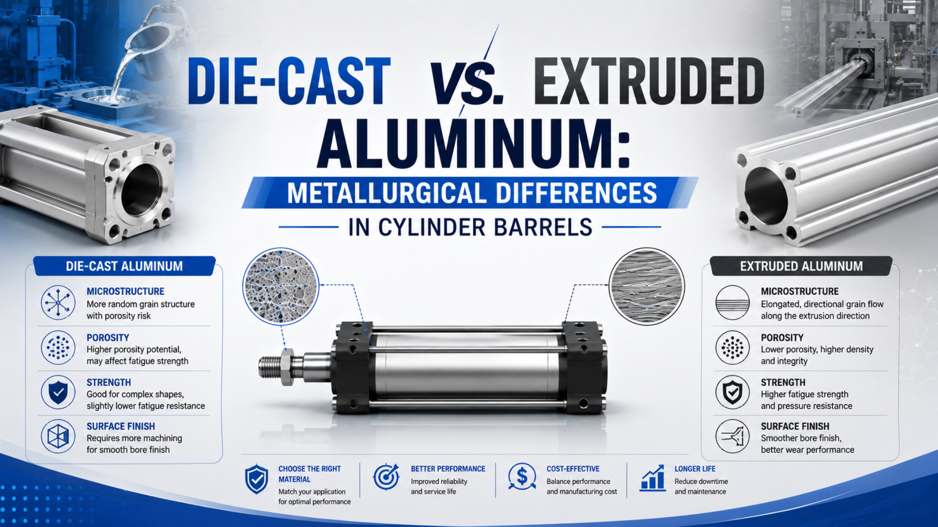
Extruded aluminum is often the logical manufacturing route for a long cylinder barrel with a constant cross-section. Die-cast aluminum is often a better fit for an end cover containing ports, cushion passages, mounting features, and other complex geometry. Those statements describe manufacturability. They do not prove which finished cylinder is stronger, safer, or longer lasting.
A useful comparison must separate the forming process from the alloy, temper, wall section, heat treatment, machining, surface treatment, defect population, and final pressure test. Otherwise, a table comparing a die-casting alloy in the as-cast condition with a heat-treated 6061 extrusion mostly measures two different material specifications, not die casting against extrusion.
High-pressure die casting is a liquid-metal forming process that fills a reusable steel die under pressure. Aluminum extrusion is a solid-billet forming process that pushes heated metal through a die to create a continuous profile.
Temper refers to the processing condition used to obtain a defined combination of properties after forming. It belongs beside the alloy designation because the same alloy can have substantially different strength and formability in different tempers.
Key Takeaways
- Extrusion suits long, constant-section barrel profiles; die casting suits complex near-net-shape covers and manifolds.
- Alloy, temper, wall thickness, finishing, and defect control determine properties alongside the forming route.
- Both processes have characteristic defects that require drawing-based inspection.
- Use the finished cylinder’s rated pressure and test evidence, never a pressure limit inferred from process alone.
What Does Each Manufacturing Process Actually Change?
The Aluminum Association defines die casting as forcing molten aluminum into a steel die under pressure, while extrusion plastically deforms a preheated solid billet through a smaller die opening. It also lists five extrusion variables that affect the result: die design, alloy, billet and container temperature, tooling temperature, and extrusion speed (The Aluminum Association, retrieved July 23, 2026).
Die casting begins with a liquid alloy. Filling, air evacuation, solidification rate, local section thickness, gating, and cooling all influence the microstructure and location of gas or shrinkage defects. It can reproduce ribs, bosses, cavities, and integrated passages at production scale with limited subsequent machining.
Extrusion begins with a solid billet heated into a workable range. The metal flows through a die to produce a continuous profile. The result can have direction-dependent properties, local recrystallization differences, residual stress, dimensional variation, and surface defects. Hollow profiles made with porthole or bridge dies also contain longitudinal extrusion seams where separated metal streams rejoin.
The Aluminum Association’s terminology guide defines the “extrusion effect” narrowly as increased longitudinal tensile properties caused by a characteristic non-recrystallized structure in certain alloys. It does not say that every extrusion has uniformly aligned grains or that every property improves in every direction (Global Advisory Group Terms and Definitions, 2011; retrieved July 23, 2026).
In our experience reviewing cylinder specifications, treating the process name as a performance rating hides the variables that actually need approval. The route changes how a component can be shaped and what defects must be controlled. Released material condition and component verification determine whether those capabilities become acceptable cylinder performance.
| Comparison point | High-pressure die casting | Aluminum extrusion | What the cylinder buyer should verify |
|---|---|---|---|
| Starting material | Molten casting alloy | Heated wrought-alloy billet | Alloy designation and material condition |
| Natural geometry fit | Complex three-dimensional near-net shapes | Long parts with a constant cross-section | Part drawing and pressure boundary |
| Directionality | Solidification structure varies with location and cooling | Flow, texture, and properties can vary by direction | Test-specimen orientation and critical load direction |
| Characteristic discontinuities | Gas porosity, shrinkage porosity, oxide films, cold shuts | Longitudinal seams, die lines, pickup, surface tearing, twist, bow | Defined defect limits and inspection method |
| Common follow-on work | Trimming, machining, deburring, coating | Straightening, cutting, machining, honing, anodizing | Finished dimensions, surface system, and cleanliness |
Alloy and Temper Come Before the Process Label
Hydro’s 6061 extrusion data gives no mechanical-property limits for the F, or as-fabricated, temper, but lists minimum tensile and yield strengths of 260 MPa and 240 MPa for T6/T6511 material. The same alloy therefore changes substantially with temper, and applicable values also depend on section thickness (Hydro Alloy 6061 Data Sheet, 2019; retrieved July 23, 2026).
That single data sheet exposes the main problem with generic “die-cast versus extruded” strength tables. If one column uses an as-cast A380 or ADC12 component and the other uses heat-treated 6061-T6, the comparison combines changes in chemistry, product form, thermal history, defect population, and test orientation.
The temper suffix isn’t administrative detail. The Aluminum Association notes that T651 and T6511 refer to different product forms and processing parameters, and that small-looking temper differences cannot be assumed insignificant (ANSI H35 Temper Interpretation, 2021; retrieved July 23, 2026).
Ask for the complete material callout. “Aluminum” is incomplete, and “6061” may still be incomplete. A usable specification identifies the alloy, temper or as-cast condition, product form, governing material standard, required properties, section to which they apply, and any approved substitutions.
| Example material entry | What it tells you | What it still does not prove |
|---|---|---|
| 6061-F extrusion | Alloy and as-fabricated condition | Minimum strength, final bore finish, pressure rating |
| 6061-T6 extrusion | Alloy plus solution heat treatment and artificial ageing | Profile geometry, defect acceptance, anodizing quality |
| A380 high-pressure die casting | Casting alloy and forming route | Local porosity, heat treatment, fatigue resistance, pressure rating |
| “Aluminum barrel” | Only a broad material family | Alloy, temper, process, dimensions, surface, or test status |
Why Extruded Aluminum Often Fits a Cylinder Barrel
Extrusion produces a long profile whose cross-section follows the die opening; the Aluminum Association also notes that commercial extrusions normally require cutting, machining, bending, welding, or finishing afterward. That combination matches many pneumatic barrels, but the extruded surface is not automatically a finished seal-running surface (The Aluminum Association, retrieved July 23, 2026).
A conventional profile cylinder may need a central bore, external flats, sensor grooves, tie-rod features, and mounting channels along the stroke. A mechanically coupled rodless cylinder can add a longitudinal slot, sealing-band seats, carriage tracks, and internal support features. Extrusion places those repeated features into one continuous profile and reduces the amount of stock that must be removed.
Long geometry also rewards process consistency. The supplier can straighten and cut the profile, machine its ends, finish the bore, apply the specified anodizing or coating, and inspect dimensions at declared axial locations. That sequence is usually more practical than trying to cast a long, slender pressure boundary with uniform finished geometry.
Still, extrusion has failure modes. A hollow profile may contain longitudinal seams. Excessive twist or bow can disturb alignment. Surface pickup or die lines can interfere with subsequent finishing, while local microstructure and residual stress can affect machining and anodized appearance. “Extruded” should start an inspection plan, not end it.
For a broader material-system view, see The Benefits of Aluminum Alloy Cylinders in Modern Automation. It separates installed mass, moving mass, corrosion protection, and air consumption instead of attributing whole-cylinder behavior to the barrel alloy.
Where Does Die Casting Fit in a Pneumatic Cylinder?
An AVENTICS ISO 15552 profile cylinder lists a 1.5 to 10 bar working range, an anodized aluminum cylinder tube, and anodized die-cast aluminum front and end covers. This commercial construction shows why one actuator can sensibly use different aluminum processes for different components (AVENTICS PRA Series Data, retrieved July 23, 2026).
End covers have a different geometry problem from barrels. They may combine a pressure port, cushion chamber, needle passage, sensor feature, mounting face, fastener bosses, seal glands, and internal flow transitions in a short component. Die casting can place much of that geometry near its final shape.
Festo publishes the same component-level distinction for a profile cylinder: a smooth-anodized wrought aluminum barrel and a coated die-cast aluminum cover (Festo Profile Cylinder Data Sheet, retrieved July 23, 2026). Neither manufacturer example proves that every die-cast cover or every extruded tube is acceptable. They show that a mixed route is normal when each part is qualified for its job.
Could a casting form part of the pressure-retaining barrel itself? Yes, if the component design, alloy, defect limits, machining allowance, sealing surface, proof testing, fatigue evidence, and change control support that use. The purchaser should not approve or reject it from the word “die-cast” alone.
The Cylinder End-Cap Strength and Mounting Guide covers port bosses, fastener load paths, cushion cavities, and mounting reactions that still require analysis after a manufacturing route is selected.
A cylinder is best mapped by component and function: the long profile solves repeated geometry, while the covers solve concentrated three-dimensional geometry. The manufacturing route follows that map.
Compare the Real Defect Mechanisms
A 2020 study of high-pressure die-cast aluminum compared porosity using metallography, X-ray radiography, and micro-computed tomography. The need for three methods is the practical lesson: defect size, shape, location, and connectivity matter, and one universal porosity percentage cannot characterize every casting (Nourian-Avval and Fatemi, 2020).
Gas porosity and shrinkage porosity don’t have identical causes or consequences. A rounded isolated pore away from a critical surface is different from a connected defect at a seal groove, threaded port, fillet, or highly stressed section. Machining can also open a subsurface pore that was invisible on the cast skin.
Vacuum assistance can reduce gas-related defects, but its effect is tied to the specific alloy, casting, equipment, and heat treatment. A 2023 study of four die-casting alloys at a reported 200 mbar vacuum level found fewer gas defects in the as-cast state, yet the mechanical-property response was not uniform across alloys and conditions (Gomes et al., 2023).
Extrusions deserve the same discipline. The Aluminum Association defines an extrusion seam as a region where metal streams weld together under pressure and temperature. In hollow profiles made with porthole dies, one or more longitudinal seams occur naturally. Acceptance therefore depends on die design, process control, section location, finishing, inspection, and the load carried by that region.
| Suspected issue | Do not assume | Better evidence |
|---|---|---|
| Casting porosity | Every casting contains the same void percentage | CT, radiography, sectioning, density, leak testing, and location-based limits |
| Extrusion seam | Every seam is either harmless or defective | Die route, seam location, etch evidence, mechanical tests, and pressure-boundary review |
| Grain direction | Longitudinal properties describe every direction | Orientation-specific material data and component stress analysis |
| Surface mark | Appearance identifies the full defect depth | Profile measurement, microscopy, dimensional inspection, and functional testing |
| Early leakage | The forming process caused the failure | Seal, bore, end-cap joint, valve, contamination, alignment, and test-boundary checks |
If leakage is the operating symptom, isolate the path before blaming the barrel material. Leakage Pathways: Micro-Analysis of Scratched Cylinder Bores explains how piston position, seal condition, connected valves, fixture leakage, and surface damage can be separated.
Bore Finish and Anodizing Are Separate Specifications
Commercial extrusions normally pass through additional fabrication or finishing before use, according to the Aluminum Association. For a pneumatic barrel, those steps may include boring, honing, cleaning, anodizing, coating, and final dimensional inspection. The forming route does not by itself establish bore roughness, roundness, straightness, or seal compatibility (The Aluminum Association, retrieved July 23, 2026).
A low arithmetic-average roughness value isn’t a complete sealing specification. It does not describe isolated scratches, waviness, taper, roundness, lay direction, peak shape, valley structure, or material ratio. The correct surface depends on the selected piston seal, lubricant, velocity, temperature, and wear system.
Anodizing also changes the surface system. Its thickness, hardness, pore sealing, dimensional allowance, and post-process cleaning need drawing control. Aggressive honing after anodizing may remove the very layer the seal was intended to contact. Conversely, applying a treatment without managing bore growth can move the finished diameter outside tolerance.
Use the Cylinder Barrel Honing and Seal-Life Guide when defining the measurement method, sampling locations, and repair limits. For corrosive service, evaluate the complete coating and fastener package with the Corrosion-Resistant Cylinder Selection Guide.
Pressure Rating Belongs to the Finished Cylinder
ISO 15552 covers detachable-mount pneumatic cylinders from 32 to 320 mm bore in a 1,000 kPa, or 10 bar, series. Its stated purpose is dimensional interchangeability. It does not assign a pressure rating from barrel process, alloy family, porosity level, or surface roughness (ISO 15552:2018, confirmed 2025; retrieved July 23, 2026).
A finished-cylinder rating depends on more than the straight wall. The analysis must include the actual profile, slot or opening, port geometry, end retention, threads, grooves, fillets, local wall transitions, manufacturing tolerances, residual stress, fatigue duty, temperature, corrosion allowance, and failure consequence.
This is especially important for rodless cylinders. A slotted mechanical-coupling profile does not behave like a closed circular tube, and a magnetically coupled cylinder uses a different barrel and force-transfer architecture. A thin-wall hoop-stress calculation can be a screening tool for a simple closed tube, but it cannot certify a finished rodless profile.
Proof and burst tests must follow the product’s released design requirement, applicable standard, and risk assessment. Don’t impose a universal “1.5 times rated pressure” rule unless the governing specification actually requires it. Record the test medium, temperature, hold time, pressure accuracy, acceptance criteria, sample plan, and whether the part was subsequently released or destroyed.
For architecture differences, compare Rodless vs. Standard Cylinders before transferring a pressure assumption from one design to another.
A Supplier Qualification Plan That Follows the Evidence
ISO 19973-3 evaluates pneumatic cylinder reliability using controlled test procedures and reports life in cycles or kilometres. That framework makes one purchasing point clear: service-life claims require a declared configuration, test boundary, operating conditions, failure threshold, and result, not a process label or an unsupported multiplier (ISO 19973-3:2015, confirmed 2021; retrieved July 23, 2026).
Start with the released drawing and bill of materials. Then connect each material and process requirement to an inspection record and a functional test. A certificate that identifies 6061-T6 cannot prove bore geometry; a smooth bore cannot prove alloy or temper; a passed leak test cannot establish fatigue life.
The strongest qualification chain has five linked layers. If any link changes, the supplier should assess whether the downstream inspection or validation must be repeated.
Use the following RFQ and approval checklist:
- Part identity: component drawing, revision, cylinder series, bore, stroke range, and pressure-boundary definition.
- Material: alloy, temper or as-cast condition, product form, governing standard, certificate type, and permitted substitutions.
- Manufacturing route: die type or extrusion route where relevant, heat treatment, machining, deburring, cleaning, and surface treatment.
- Dimensions: wall sections, bore diameter, roundness, straightness, taper, twist, bow, groove geometry, threads, and datum scheme.
- Surface system: bore texture parameters, measurement settings, anodizing or coating requirement, thickness, hardness if required, and visual limits.
- Defect control: prohibited defect types, acceptance location and size, CT or radiography requirements where justified, sampling plan, and disposition rules.
- Functional evidence: leakage, proof, burst, fatigue, motion, temperature, corrosion, and contamination tests appropriate to the exact product.
- Traceability: heat, batch, cavity, extrusion lot, process revision, inspection equipment, calibration status, and supplier change notification.
Visual clues can support receiving inspection, but they don’t establish the complete route. Parting lines and ejector marks suggest casting; continuous longitudinal features suggest extrusion. Machining, blasting, painting, or anodizing may remove or hide those clues. Confirm the process through the drawing, material certificate, and supplier records.
Which Route Should You Specify?
Two commercial profile-cylinder examples pair aluminum tubes or wrought-aluminum barrels with die-cast aluminum covers, while ISO 15552 separates interchangeability dimensions from material selection. The practical choice is therefore component-specific: specify extrusion where continuous profile geometry adds value, and die casting where complex near-net geometry adds value, then qualify each finished part (AVENTICS and ISO, retrieved July 23, 2026).
Choose an extruded barrel profile when the design needs:
- a long, repeatable cross-section;
- integrated sensor, mounting, carriage, or sealing-band features;
- controlled straightness and profile geometry after finishing;
- an established wrought alloy and temper;
- a defined path for machining, honing, anodizing, and inspection.
Choose a die-cast component when the design benefits from:
- complex ports, ribs, bosses, cavities, and mounting features;
- near-net-shape production at suitable volume;
- reduced machining of three-dimensional geometry;
- casting-specific defect control and traceability;
- pressure and fatigue validation for the actual component.
Reject both routes when the supplier cannot identify the alloy and condition, connect the process to a released drawing, define defect and surface limits, or provide the required functional evidence. Cheap material paperwork does not rescue an uncontrolled barrel, and an impressive pressure test does not authorize undocumented substitutions.
Conclusion
The Aluminum Association identifies at least five extrusion variables that affect final properties, and current pneumatic products show extruded or wrought-aluminum barrels working alongside die-cast covers. Those facts support a component-level decision, not a universal ranking of the two processes (The Aluminum Association and AVENTICS, retrieved July 23, 2026).
Extrusion usually fits long, constant-section cylinder barrels because it places repeated geometry into a continuous profile. Die casting usually fits complex covers and integrated passages. Either process can produce an unacceptable component when the alloy, condition, defects, dimensions, finishing, or validation are uncontrolled.
Specify the component first. Then define material, manufacturing route, finished geometry, surface system, defect limits, and test evidence. That sequence turns a process preference into an auditable pneumatic-cylinder requirement.
Aluminum Cylinder Barrel FAQs
ISO 15552 covers a 10 bar dimensional series but does not prescribe barrel alloy or manufacturing process. These five questions keep purchasing decisions tied to the actual component, its released material condition, finished inspection, and model-specific pressure evidence rather than a generic process label (ISO 15552:2018, confirmed 2025).
Is extruded aluminum always stronger than die-cast aluminum?
No. Strength depends on alloy, temper or as-cast condition, section thickness, processing history, defect distribution, and test direction. Hydro’s 6061 data alone ranges from no mechanical-property limits in F temper to specified T6/T6511 minimums. Compare released material specifications and component evidence, not two process names.
Does a die-cast pneumatic component always contain 2 to 5 percent porosity?
No. Porosity varies with alloy, geometry, gating, air evacuation, process settings, solidification, sampling location, and measurement method. Its shape and position can matter more than a bulk percentage. Set component-specific limits and use appropriate inspection such as CT, radiography, sectioning, density, machining inspection, or leak testing.
Can an ISO 15552 cylinder use die-cast aluminum end covers?
Yes. ISO 15552 governs the dimensional series needed for interchangeability, not one compulsory manufacturing route. Commercial ISO 15552 cylinders use anodized aluminum tubes with die-cast aluminum covers. Confirm the exact model’s materials, working-pressure range, environment, mounting, and test documentation rather than inferring construction from the standard.
Does extrusion provide the finished bore surface needed by piston seals?
Not by itself. Commercial extrusions normally receive downstream fabrication and finishing. A cylinder bore may require machining, honing, anodizing or coating, cleaning, and final measurement. Specify the seal manufacturer’s counter-surface requirements together with bore size, form, texture method, coating condition, and defect limits.
What documents should accompany an aluminum cylinder barrel?
Request the released drawing, alloy and temper or as-cast callout, material certificate, process and heat-treatment records where required, dimensional and surface inspection, defect-control results, coating or anodizing evidence, leak and pressure-test records, lot traceability, and change notification. Match the document depth to failure consequence and application risk.