

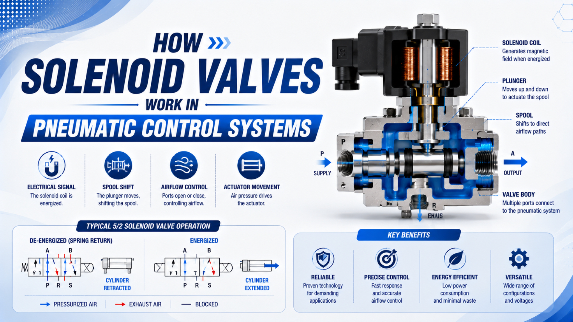
A pneumatic solenoid valve is an electro-pneumatic directional-control device that converts an electrical command into a change of compressed-air paths. The PLC requests a state, the output circuit drives a coil, an armature moves, and a valve element changes which ports connect. In a pilot-operated valve, pilot pressure must also move the main stage before the actuator can respond.
That sequence matters because a command, an energized coil, a shifted spool, and a moving cylinder are four different facts. An illuminated connector or audible click confirms only part of the chain. Reliable design and troubleshooting verify each state separately, from the PLC output to the actuator’s measured motion.
Key Takeaways
- A solenoid valve is an electro-pneumatic interface and final switching element; the PLC remains the controller.
- Direct-operated valves move the main sealing element electromagnetically. Pilot-operated valves add pressure and exhaust dependencies between the solenoid and the main stage.
- Port count, position count, normal state, return method, flow data, operating pressure, coil specification, and environmental rating all belong to the exact order code.
- A coil click does not prove that the main spool shifted, and a shifted spool does not prove that enough air reached the actuator.
- De-energizing an ordinary directional valve is not automatically a safe isolation or load-holding measure.
How Does a Solenoid Valve Fit into Pneumatic Control?
ISO 11727:1999 is an 11-page identification standard covering valve ports, control mechanisms, and solenoid leads. Its scope makes the engineering boundary clear: the electrical operator and the pneumatic valve are connected parts of one device, but the device still needs a defined port function and control state (ISO 11727).
In a basic control loop, the PLC evaluates input signals and logic. Its output module then energizes or de-energizes the valve circuit. The valve does not decide when the machine should move; it implements the requested pneumatic state.
The complete signal-and-energy path is:
- Control decision: PLC logic requests a valve state.
- Electrical output: A transistor, relay, manifold driver, or safety output applies the specified electrical condition.
- Electromagnetic actuation: Coil current creates magnetic force and moves an armature or plunger.
- Pilot conversion, when used: A small pilot passage pressurizes or vents a main-stage control area.
- Main valve movement: A spool, poppet, or diaphragm reaches a defined position.
- Pneumatic routing: Supply, work, and exhaust ports connect according to that position.
- Actuator response: Pressure and flow create cylinder, gripper, or rotary-actuator motion.
The useful abstraction is a state chain, not a single “valve on” flag. A machine can have a true PLC output bit, an illuminated connector, and even armature movement while the main spool remains in its previous state. Treating these observations as separate variables prevents electrical evidence from being mistaken for pneumatic evidence.
For a broader explanation of valve construction and general airflow control, see how pneumatic solenoid valves control compressed-air flow. This article stays focused on the control boundaries that must be verified.
What Happens Between PLC Output and Actuator Motion?
ISO 12238:2023 uses 17 pages to define shifting-time measurement for electrically or pneumatically operated directional valves, including monostable and bistable designs with two or three positions. That narrow scope shows why a valve’s switching time cannot be inferred from a PLC timestamp or treated as the complete cylinder response (ISO 12238).
At the electrical boundary, verify the output type before taking measurements. A sourcing transistor, sinking transistor, relay contact, and intelligent manifold driver do not present the same circuit. A connector LED can illuminate with too little current to complete pull-in, while an output module may report a healthy command without detecting a disconnected load.
At the electromagnetic boundary, current creates magnetic force. The armature must overcome its return spring, pressure force, friction, and any contamination through the full stroke. Electronic drivers can use peak-and-hold control; TI’s DRV110, for example, regulates a higher peak current before a lower holding current rather than applying one unchanging drive level (Texas Instruments DRV110).
At the pneumatic boundary, the shifted valve must provide the intended pressure and flow at the work port. Tubing restriction, silencers, exhaust backpressure, undersized fittings, a closed upstream isolation valve, or a reversed connection can prevent the actuator from responding normally even when the valve itself shifts.
Finally, actuator motion depends on load, friction, opposing chamber pressure, cushioning, and mechanical alignment. Valve shifting time is only one part of the interval from command to confirmed position. For a timing-focused breakdown, use the separate solenoid valve response-time guide.
How Do Direct-Acting and Pilot-Operated Valves Differ?
SMC’s directional-valve technical data distinguishes three operating methods: internal pilot, external pilot, and direct operation. The distinction is not cosmetic. It determines whether coil action moves the main valve element itself or only switches a smaller passage whose pressure differential then moves the main stage (SMC technical data).
| Operating method | What the solenoid moves | Additional dependency | Diagnostic consequence |
|---|---|---|---|
| Direct operated | Main poppet, plunger, sealing element, or spool | Electromagnetic force must overcome the main-stage forces | Coil current and armature travel are close to the main airflow function. |
| Internal pilot operated | Small pilot poppet or passage | Inlet pressure and a usable pilot pressure differential | A click can occur while the main stage remains unshifted. |
| External pilot operated | Pilot passage supplied from a separate port | Correct external pilot pressure and pilot exhaust | Main supply pressure alone does not prove pilot availability. |
Parker’s general-purpose solenoid-valve catalog states that pilot-operated constructions require a specified minimum pressure differential, while direct-acting constructions do not rely on that same differential. The exact limit belongs to the selected model, medium, port arrangement, and operating direction—not to the words “pilot operated” alone (Parker catalog).
If the valve is internally piloted and inlet pressure falls below its specified range, the pilot poppet may still move while the main spool does not. If the design is externally piloted, verify the separate pilot port and its exhaust path. The pilot-operated valve guide covers that architecture in more detail.
How Do Ports, Positions, and Returns Define Behavior?
ISO 11727 standardizes identification conventions, but the same port count does not make valves interchangeable. A complete functional description also needs the position count, normal or stored state, actuation method, return method, manufacturer symbol, and order code (ISO 11727).
The notation “5/2” means five ports and two switching positions; “5/3” means five ports and three positions. It does not, by itself, specify which ports connect in each position. A 5/3 center state may be closed, exhausted, or pressurized depending on the spool function.
| Function | Typical control purpose | Information still required |
|---|---|---|
| 2/2 | Start or stop one flow path | Normally closed or normally open, flow direction, pressure range |
| 3/2 | Supply and exhaust one work port | Normal state, port connections, return method |
| 5/2 | Reverse two work ports | Single- or double-solenoid actuation, stored state, exhaust arrangement |
| 5/3 | Add a center position | Exact center connections, centering method, leakage behavior |
“Normally closed” and “normally open” describe the de-energized flow state of a defined path. “Monostable” means the valve returns to a designated state when the actuation signal is removed. “Bistable” means it can remain in either of two stable states. These terms answer different questions and should not be used as mutually exclusive labels.
A single-solenoid spring-return 5/2 valve usually moves to its spring-defined state when power is removed. A double-solenoid bistable 5/2 valve may retain its last state after both coils are de-energized. The detailed 3/2 versus 5/2 comparison explains common application choices without replacing the exact valve symbol.
Why Doesn’t De-Energized Automatically Mean Safe?
ISO 4414:2010 is a 38-page general-rules and safety standard for pneumatic systems and components. Its system-level scope is important: safety cannot be inferred from one valve’s coil state. Stored pressure, gravity, leakage, trapped volume, controller faults, and restart behavior must all be considered in the risk assessment (ISO 4414).
Removing electrical power can produce several different pneumatic outcomes:
- A spring-return valve may connect a work port to exhaust.
- A bistable valve may remain in its last position.
- A 5/3 valve may move to a center condition whose connections depend on the spool.
- A pilot-operated valve’s position or switching behavior is not assured if pressure decays outside its specified range.
- A cylinder may continue moving because compressed air remains stored in tubing and chambers.
- A vertical load may descend through valve, seal, or fitting leakage.
A 5/3 closed-center valve blocks its external work ports in the nominal center position, but that does not guarantee load holding. Air is compressible, and real valves, fittings, and cylinder seals have leakage. A purpose-designed rod lock, mechanical restraint, counterbalance arrangement, or monitored safety function may be needed for the actual hazard.
Likewise, an ordinary directional valve is not automatically a safety-rated isolation or exhaust device. Use components and architectures with documented safety functions, diagnostics, fault assumptions, and performance levels appropriate to the machinery risk assessment.
The safest diagnostic wording is also the most precise: “the coil is de-energized” describes an electrical state, not a safe machine state. Record spool position, port pressures, stored energy, and load restraint separately before personnel enter a hazardous area.
How Can You Verify Each Stage Without Guessing?
The SMC SY5200-X25 sheet lists 24 VDC, 0.4 W, and 17 mA. Response is 12 ms or less without light and surge suppression. With suppression, it is 15 ms or less for S/Z variants and 12 ms or less for R/U variants. This split shows why another valve needs its own pass limits (SMC SY5200-X25).
Use a written state table before changing parts:
| Requested state | Test point | Expected evidence | If evidence is missing |
|---|---|---|---|
| PLC requests ON | Logic or output status | Command bit changes | Check interlocks, sequence logic, and safety conditions. |
| Output energizes load | Connected coil terminals | Correct voltage under load | Check output type, connector, cable, fuse, and common return. |
| Coil produces action | Current waveform or magnetic/armature check | Model-consistent pull-in and holding behavior | Check coil order code, driver, suppression, armature, and contamination. |
| Pilot stage operates | Pilot supply and exhaust | Pressure changes as the symbol requires | Check minimum pressure, external pilot source, and blocked pilot exhaust. |
| Main stage shifts | Position indication or controlled flow test | Intended spool or poppet state | Check manual override, spool friction, contamination, and assembly. |
| Work port changes | Pressure gauge at the work port | Pressure rises or falls as expected | Check supply, port mapping, mufflers, fittings, and restrictions. |
| Actuator moves | Position sensor or measured stroke | Correct direction, time, and final position | Check load, alignment, cylinder friction, cushioning, and opposing pressure. |
A practical commissioning sequence
- Make the machine safe. Isolate hazardous motion, restrain gravity loads, and release stored energy according to the machine procedure.
- Record the exact valve identity. Capture the complete order code, symbol, voltage, frequency, connector, manifold station, and datasheet revision.
- Confirm the requested state. Check PLC logic, interlocks, output diagnostics, and whether the manual override has altered the expected condition.
- Measure at the connected load. A disconnected voltage reading does not test voltage drop through the actual circuit.
- Compare current with model data. Interpret peak, hold, PWM, and release behavior using the valve and driver documentation.
- Check pilot conditions. On pilot-operated designs, measure the relevant pilot supply and inspect the exhaust path.
- Verify the main stage. Use a position indicator, pressure transition, or controlled flow test approved for the machine.
- Measure the pneumatic result. Check supply pressure, work-port pressure, exhaust restriction, and actuator motion under a defined load.
- Save the acceptance record. Keep test pressure, voltage, temperature, load, timing reference, and pass limits with the order code.
In my experience commissioning pneumatic controls, the state table works best from left to right, stopping at the first failed boundary. Repeatedly forcing the output or swapping coils without recording that boundary tends to erase evidence and can turn one fault into several unverified assumptions.
Which Specifications Matter Before Replacement?
ISO 6358-1 defines test methods for compressible-fluid flow characteristics. Its 2026 Amendment 2 adds six pages on uncertainty. Therefore, compare flow data obtained by consistent methods and conditions; a port thread size is not a complete capacity specification (ISO 6358-1; Amendment 2:2026).
Before approving a replacement, verify:
- Valve function: Port count, position count, center condition, normal state, and flow direction.
- Operating method: Direct, internal pilot, external pilot, or another documented architecture.
- Pressure limits: Main inlet range, minimum differential, pilot range, proof pressure, and allowable backpressure.
- Flow characteristics: Manufacturer data under stated test conditions; use Cv only when the definition and basis are consistent.
- Electrical identity: AC or DC, nominal voltage, frequency, tolerance, power or current, duty, polarity, suppression, connector, and output compatibility.
- Timing: Energizing and de-energizing values, test pressure, temperature, load, and the manufacturer’s response definition.
- Medium and environment: Air quality, lubrication rule, temperature, materials, ingress rating, washdown chemicals, and hazardous-location approvals.
- Mechanical interface: Port threads, manifold pattern, mounting, manual override, envelope, and cable orientation.
Do not substitute a 24 VDC coil for a 24 VAC coil merely because the voltage number matches. Windings, rectification, shading components, suppression, tolerances, and connectors can differ. Match the full approved coil and valve order code.
IEC 60529 defines enclosure ingress-protection classifications. An IP65 or IP67 marking describes protection against specified access, dust, and water conditions; it does not establish a machinery safety function or explosion-protection approval (IEC 60529).
For capacity work, use the dedicated explanation of flow coefficient and pneumatic valve sizing. Oversizing a valve does not inherently increase a cylinder’s air consumption; cylinder volume and pressure dominate consumption, while valve capacity mainly affects pressure drop and motion dynamics.
Commission the Entire State Chain
ISO 12238 separates valve shifting-time measurement from the actuator system, while ISO 4414 addresses pneumatic equipment at system level. Together, they support commissioning records with distinct electrical, valve, pressure, and mechanical acceptance limits instead of one ambiguous “cycle time” result (ISO 12238; ISO 4414).
A useful commissioning sheet contains one row for each requested valve state. Record the controller condition, connected coil voltage, current behavior, pilot pressure where applicable, work-port pressures, actuator position, motion time, load, supply pressure, and temperature. The test should cover energizing, de-energizing, restart, loss of supply, and any stored-state behavior relevant to the risk assessment.
Acceptance limits must come from the exact valve, driver, manifold, tubing, actuator, and machine requirement. A catalog switching time measured at one pressure does not prove the installed cylinder will meet its cycle-time requirement. Conversely, a slow cylinder does not prove that the valve shifted slowly.
The Useful Mental Model Is State, Not Click
The 17-page scope of ISO 12238 focuses on directional-valve shifting, while ISO 10094-1 separately covers characteristics for continuously controlled electro-pneumatic pressure control valves. Ordinary on/off directional valves should therefore be understood as flow-path switching devices, not assumed to regulate outlet pressure (ISO 12238; ISO 10094-1).
The most dependable mental model is a series of verified states:
PLC request → loaded output → coil current → armature motion → pilot pressure → main valve position → port pressure → actuator motion
A direct-operated valve removes the pilot-pressure stage, but it does not remove the need to verify the electrical load, main element, airflow, and actuator. A pilot-operated valve gains main-stage force from compressed air but adds pressure and exhaust dependencies.
Design the circuit by defining the required state in normal operation, power loss, pressure loss, restart, and credible fault conditions. Troubleshoot by stopping at the first state that does not match the request. That approach is traceable and less prone to diagnostic assumptions than using sound, indicator lights, or component replacement as proof.
Pneumatic Solenoid Valve FAQs
ISO 11727 and ISO 12238 separate identification from timing, while manufacturer documentation adds model-specific voltage, current, pressure, and response limits. The answers below preserve those boundaries: they explain what each observation proves and what still needs to be measured before a valve or actuator can be declared healthy.
Does an illuminated connector LED prove that the valve shifted?
No. The LED shows that some electrical potential reaches the indicator circuit. It does not prove adequate voltage at the loaded coil, correct current, complete armature travel, usable pilot pressure, or main-spool movement. Verify connected voltage and current, then confirm the pneumatic state with position, flow, or pressure evidence.
Why does a solenoid valve click while the cylinder does not move?
The click may be the armature or pilot poppet, not the main spool. Possible causes include inadequate pilot pressure, blocked pilot exhaust, a stuck spool, missing main supply, incorrect port connections, restricted exhaust, insufficient work-port pressure, or an actuator problem. Follow the state chain to find the first failed boundary.
Can a 5/3 closed-center valve hold a cylinder safely?
Not by itself. Closed center nominally blocks the work ports in the center position, but compressed air stores energy and real valves, fittings, and cylinder seals leak. A risk assessment may require a mechanical restraint, rod lock, monitored valve architecture, or another purpose-designed load-holding measure.
Can a 24 VDC coil replace a 24 VAC coil?
Only when the valve manufacturer approves the complete replacement order code. AC and DC coils may differ in winding, magnetic design, shading components, rectification, tolerance, suppression, connector, and power behavior. Matching the number “24” does not establish electrical or mechanical compatibility with the operator.
Is valve shifting time the same as cylinder response time?
No. Valve shifting time covers the valve’s transition under defined test conditions. Cylinder response also includes output delay, pressure propagation, tubing and fitting restrictions, chamber filling or exhausting, load, friction, cushioning, and sensor thresholds. Measure the installed command-to-position interval separately from the valve specification.
Sources
- ISO 11727:1999, Pneumatic fluid power—Identification of ports and control mechanisms of control valves and other components, identification of ports, control mechanisms, and solenoid leads. Retrieved 2026-07-26.
- ISO 12238:2023, Pneumatic fluid power—Directional control valves—Measurement of shifting time, scope and test boundary for shifting time. Retrieved 2026-07-26.
- ISO 4414:2010, Pneumatic fluid power—General rules and safety requirements for systems and their components, system-level pneumatic safety requirements. Retrieved 2026-07-26.
- ISO 6358-1:2013 and ISO 6358-1:2013/Amd 2:2026, test methods for compressible-fluid flow-rate characteristics and uncertainty. Retrieved 2026-07-26.
- ISO 10094-1:2021, Pneumatic fluid power—Electro-pneumatic pressure control valves, scope for continuously controlled pressure valves. Retrieved 2026-07-26.
- Texas Instruments DRV110, peak-and-hold solenoid-current control. Retrieved 2026-07-26.
- SMC Solenoid Valve Technical Data, direct, internal-pilot, and external-pilot operating methods. Retrieved 2026-07-26.
- SMC SY5200-X25 Product Information, model-specific voltage, current, power, and response example. Retrieved 2026-07-26.
- SMC SY3000/5000/7000 Instruction Manual, connector-dependent protection, suppression, and operating-range cautions. Retrieved 2026-07-26.
- Parker General Purpose Solenoid Valves Catalog, direct-acting and pilot-operated pressure-differential requirements. Retrieved 2026-07-26.
- IEC 60529, Degrees of protection provided by enclosures, IP classification scope. Retrieved 2026-07-26.