

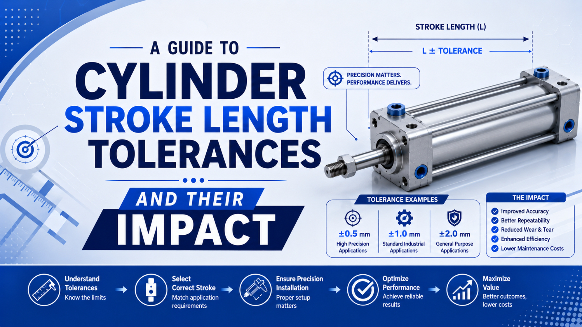
Cylinder stroke length tolerance is the permitted difference between nominal stroke and the actual end-to-end travel of a specified cylinder. It does not, by itself, state where the tooling will stop, how closely the axis repeats, or whether the finished machine will hold a part-level tolerance. That distinction changes how an engineer reads a catalog. A compliant cylinder can still miss the process point because of a loose bracket, cushion compression, side load, sensor window, or flexible fixture. Start with the required result at the machine, then assign a separate limit to each contributor.
Key Takeaways
- Catalog limits are model-specific: Parker P1D-B lists +0.3/+2.0 mm for strokes up to 500 mm, while other families use different bands.
- Stroke tolerance isn’t accuracy.
- Verify from documented datums and operating conditions; include measurement uncertainty.
- Use stops, feedback, or controlled motion when full-stroke travel cannot satisfy the part-level requirement.
What Does Cylinder Stroke Length Tolerance Actually Mean?
Festo’s operating guide states that standard-cylinder stroke deviations are always positive; it lists +1.5 mm for ISO 6432 cylinders up to 500 mm and separate allowances for ISO 15552 sizes. Stroke tolerance is therefore a permitted manufacturing range around nominal travel, not a universal positioning specification. Sign matters (Festo, General Operating Conditions, retrieved 2026-07-10).
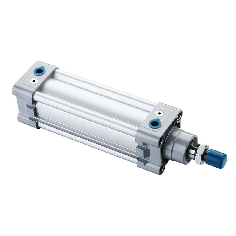
Nominal stroke is the ordered travel value, such as 100 mm. Actual stroke is the measured distance between the defined retracted and extended reference positions. Stroke tolerance is the permitted band that tells you which measured values are acceptable for that product and configuration. Direction changes the result. For example, a notation of 0/+1.0 mm means a nominal 100 mm stroke may measure from 100.0 to 101.0 mm under the supplier’s stated conditions. It does not mean 99.0 to 101.0 mm. Likewise, Parker’s +0.3/+2.0 mm band means both limits are above nominal.
Why are generic ±1 mm assumptions risky? They change the acceptance boundary. Such a conversion may reject a conforming cylinder at one end and accept an unsupported short stroke at the other. Read the footnotes too. SMC’s CQ2 catalog states that its stroke-length tolerance does not include the amount of bumper change. If a rubber bumper compresses differently with load, speed, temperature, or age, the observed tooling position can change even though the manufactured stroke remains within its catalog band (SMC, CQ2 Compact Cylinder, retrieved 2026-07-10).
For the basic motion and force relationship behind a standard cylinder, see the guide to how pneumatic cylinders power automation. That mechanism is separate from the dimensional acceptance rule discussed here.
Why Is Stroke Tolerance Not the Same as Positioning Accuracy?
SMC separates two numbers in its CE2 catalog: stroke-length tolerance is +1.0 mm up to 250 mm and +1.4 mm from 251 to 1,000 mm, while sensor accuracy is ±0.2 mm. Those specifications describe different properties and should never be substituted (SMC, CE2 Stroke Reading Cylinder, retrieved 2026-07-10).
Positioning accuracy is closeness to a commanded or reference position. Repeatability is the spread of repeated results at the same command, so keep both terms separate from stroke tolerance in a drawing, RFQ, and acceptance report:
| Term | What it answers | Typical evidence |
|---|---|---|
| Stroke-length tolerance | How far may actual full travel differ from nominal? | Product data sheet and dimensional inspection |
| Accuracy | How close is the measured position to the commanded or reference position? | Calibrated position measurement under stated conditions |
| Repeatability | How tightly do repeated results cluster at the same command? | Repeated-cycle data with the same setup |
| Sensor resolution | What is the smallest position increment the sensor or counter reports? | Sensor and electronics specification |
| Process tolerance | How much variation can the part or operation accept? | Product drawing, quality plan, or machine acceptance specification |
Resolution isn’t accuracy. Even a counter that displays 0.1 mm increments can report a position with a larger system error. The SMC CE2 catalog makes this visible by listing 0.1 mm/pulse resolution and ±0.2 mm accuracy, then warning that installed-machine accuracy can vary with mounting and surroundings. Start the tolerance budget at the accepted part feature, then work backward through the fixture, stop, guide, carriage, cylinder, mounting, sensor, and control logic. This load-path view prevents the cylinder’s catalog number from becoming the default explanation for every positioning error.
Normal magnetic switches add end-zone confirmation, not a complete measurement of travel. The pneumatic cylinder position-sensing guide explains the difference between reed switches, solid-state switches, analog transmitters, magnetostrictive sensors, and encoders. That’s all a switch can confirm.
Product-Specific Tolerance Examples
SMC lists 0/+1.0 mm for CQ2, while Parker lists +0.3/+2.0 mm for P1D-B strokes up to 500 mm and +0.3/+3.0 mm above 500 mm. Limits vary by series, stroke, and supplier. Context decides (Parker, P1D-B Pneumatic ISO Cylinders, retrieved 2026-07-10; SMC, CQ2, retrieved 2026-07-10).
| Published example | Stroke range | Stated stroke deviation | Boundary to preserve |
|---|---|---|---|
| SMC CQ2 pneumatic type | Catalog standard strokes | 0/+1.0 mm |
Bumper change excluded |
| SMC CE2 stroke-reading cylinder | Up to 250 mm | +1.0 mm |
Position sensor specified separately |
| SMC CE2 stroke-reading cylinder | 251-1,000 mm | +1.4 mm |
Position sensor specified separately |
| Parker P1D-B ISO cylinder | Up to 500 mm | +0.3/+2.0 mm |
Applies to the named series |
| Parker P1D-B ISO cylinder | Over 500 mm | +0.3/+3.0 mm |
Applies to the named series |
| Festo ISO 6432 standard cylinder | Up to 500 mm | +1.5 mm |
General operating-conditions table |
These figures aren’t a ranking of cylinder quality. They are examples of different declared limits. Smaller numbers don’t prove better installed positioning because the products, sensing arrangements, cushioning, stroke ranges, and measurement conditions differ.
The six cited Festo, Parker, and SMC tolerance examples use positive-only upper deviations; they do not support a universal symmetric +/-1 mm rule. The recurring specification risk is losing the lower-bound sign or a bumper footnote when a catalog value is copied into an RFQ. Treat the table as product-specific source evidence, not a manufacturer-wide statistical survey.
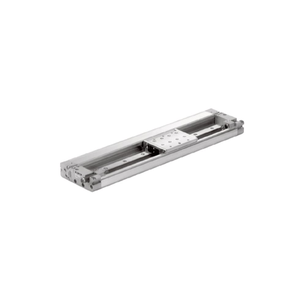
ISO 15552:2018 covers detachable-mounting pneumatic cylinders from 32 to 320 mm bore at a maximum rated pressure of 1,000 kPa, or 10 bar. Its purpose is dimensional interchangeability across basic, mounting, and accessory interfaces (ISO 15552:2018, confirmed current 2025). Supplier product sheets still decide the ordered cylinder’s acceptance band. Scope matters. Rodless products need the same caution because a guided carriage, sealing-band design, end cover, shock absorber, or adjustable stop can change which dimension defines usable travel. Review the exact drawing rather than importing a rod-cylinder number into a rodless-cylinder RFQ.
How Should You Measure and Verify Actual Stroke?
NIST Technical Note 1297 defines expanded uncertainty as U = k × uc and states that k = 2 gives approximately 95% coverage when its assumptions hold. A stroke report should therefore include observed travel, instrument uncertainty, setup, temperature, pressure state, load, and datum, not just one caliper reading. Uncertainty belongs in the result (NIST TN 1297, updated 2026).
First define the measurand, the exact quantity being measured. Is it piston-rod travel, carriage travel, distance between two tooling faces, sensor switching separation, or finished-part movement? Those results can differ even on the same machine.
Use this verification sequence:
- Identify the ordered configuration. Record the series, bore, nominal stroke, cushion or bumper option, rod or carriage arrangement, and any adjustable stop.
- Choose stable datums. Use rigid surfaces tied to the cylinder or machine.
- Define the operating state. Record whether the check is unpressurized, pressurized, unloaded, or under the working load. Include supply pressure, orientation, temperature, dwell, and direction of approach.
- Control alignment. Keep the measuring axis parallel to motion and remove unintended side load.
- Record endpoints. Subtract the retracted reference from the extended reading.
- Repeat under the acceptance method. Separate mean travel from cycle-to-cycle scatter. The contract should define sample size, warm-up state, outlier treatment, and the final pass rule.
- State measurement uncertainty. Include instrument calibration, resolution, alignment, fixturing, thermal effects, and operator or setup variation.
- Apply the correct band. Preserve its signs and exclusions.
actual stroke = extended reference reading - retracted reference reading

reported result = actual stroke ± expanded measurement uncertainty
Could a 0.01 mm display prove a 0.01 mm stroke tolerance? No. Display resolution is only one uncertainty component. If alignment, datum stability, temperature, or fixture movement contributes more error, the extra decimal places create confidence without better evidence.
A useful acceptance rule protects against false passes near the limit. If the measured value is close enough to the specification boundary that measurement uncertainty crosses that boundary, the report should follow the agreed decision rule instead of silently rounding toward acceptance.
For custom or modified cylinders, carry this measurement method from drawing approval through final acceptance. The custom pneumatic cylinder lifecycle guide shows where drawing, inspection, FAT, installation, and commissioning records belong. Document it.
When Does Standard Stroke Tolerance Stop Being Enough?
Festo’s SDBT-MSX sensor has a 20 mm detection range and a 2 to 15 mm switching window. That can confirm the piston entered a sensing zone, but it doesn’t convert a cylinder into a precision positioning axis. Use process requirements to choose the control layer. Feedback matters (Festo, SDBT-MSX, retrieved 2026-07-10).
Choose the next control layer from the actual job:
- External mechanical stop: Use a rigid machine datum when the cylinder end cap shouldn’t define final tooling position. Check bracket stiffness, stop strength, impact energy, rebound, accessibility, adjustment locking, and wear before approval.
- Cylinder switch: Confirm a binary end zone; don’t treat it as continuous feedback.
- Continuous position sensor: Use it when the controller needs measured travel or an intermediate position. Verify the sensor, mounting, electronics, scaling, and complete installed system rather than quoting resolution alone.
- Servo-pneumatic control: Choose it for commanded mid-stroke positions or controlled profiles when the project can support tuning.
- Electric actuator: Use one when several programmable positions, stiff closed-loop motion, recipe changes, controlled acceleration, force feedback, or traceable position records justify a deeper motion-control architecture.
- Custom stroke or adjustable stop: Narrow the mechanical band around a machine-specific dimension and put the inspection method on the drawing.
Selection isn’t triggered simply by “tight tolerance.” It starts with the location of the datum. Datum first. If the accepted part feature references a fixture shoulder, make that shoulder and its stop architecture control the result. Asking the cylinder to recreate an external machine datum through air compressibility, mounting compliance, and cushion behavior adds avoidable error sources. If the axis only needs two confirmed end positions, compare the boundary with the low-friction cylinder guide. Low friction can improve smooth motion, but it doesn’t create feedback. If several positions or motion profiles are required, use the cylinder and electric actuator precision comparison.
For high cycle rates, stroke tolerance is only one input. Valve flow, tubing volume, load, cushion-entry speed, and stop energy can dominate the observed endpoint. Record those items with the high-speed pneumatic cylinder specification checklist. Timing exposes the gap.
Put These Fields in the RFQ
| RFQ field | Required entry |
|---|---|
| Cylinder identification | Series, bore, nominal stroke, action, rod or rodless type |
| Stroke requirement | Supplier standard or custom band, with tolerance direction |
| Reference points | Surfaces or features that define retracted and extended positions |
| Operating state | Pressure, load, orientation, speed, cushion, and temperature |
| Process requirement | Accuracy, repeatability, resolution, or part tolerance, named separately |
| Position confirmation | No sensor, binary switch, analog transmitter, encoder, or external gauge |
| Measurement method | Instrument, datums, approach direction, uncertainty, and sample plan |
| Acceptance rule | Pass boundary, treatment of uncertainty, and documentation required |
No current site calculator matches this job. Stroke-time, force, and flow calculators answer different questions, so adding one here would distract from the dimensional and metrology workflow.
FAQ About Cylinder Stroke Length Tolerances
Parker’s P1D-B table allows an upper deviation of +2.0 mm for strokes up to 500 mm, while SMC’s CQ2 example allows +1.0 mm. Model identity controls the answer. This FAQ treats those figures as examples and separates mechanical travel, sensing, calibration, and process acceptance (Parker P1D-B; SMC CQ2, retrieved 2026-07-10).
Are pneumatic cylinder stroke tolerances normally written as ± values?
Not always. SMC lists 0/+1.0 mm for the cited CQ2 configuration, while Parker lists +0.3/+2.0 mm for P1D-B strokes up to 500 mm. Copy the exact lower and upper limits from the ordered model’s data sheet rather than converting them into a symmetric ± value.
Can calibration tighten a cylinder’s mechanical stroke tolerance?
Calibration can quantify measurement error or help adjust a sensor, stop, or control offset; it doesn’t remachine the cylinder’s mechanical travel. NIST notes that k = 2 gives about 95% coverage under stated assumptions. Report uncertainty and adjust the controllable element instead of relabeling the manufactured tolerance.
Does a tighter stroke tolerance guarantee better repeatability?
No. SMC’s CE2 catalog separately lists +1.0 or +1.4 mm stroke tolerance, 0.1 mm/pulse resolution, and ±0.2 mm sensor accuracy. Repeatability still depends on the stop, guidance, load, pressure, speed, cushion behavior, sensor window, mounting stiffness, and the test method used on the machine.
What should I specify when ordering a custom stroke?
State nominal travel, tolerance direction, datums, pressure state, load, cushion or bumper, temperature, approach direction, measurement uncertainty, and acceptance rule. ISO 15552 covers 32 to 320 mm bores at up to 1,000 kPa, but a custom-stroke agreement still needs supplier-specific drawing and inspection requirements. Write it down.
Can a standard pneumatic cylinder achieve sub-millimeter positioning?
Complete axes may achieve sub-millimeter results with a rigid stop, suitable feedback, controlled approach, and verified conditions, but nominal cylinder stroke tolerance doesn’t prove it. SMC’s CE2 uses a dedicated position-reading system with ±0.2 mm stated accuracy and still requires customer calibration after installation on the machine. Test the machine.
Sources and retrieval notes
- ISO 15552:2018, Pneumatic fluid power cylinders, official scope for interchangeable basic, mounting, and accessory dimensions across 32 to 320 mm bores at a maximum rated pressure of 1,000 kPa; retrieved 2026-07-10.
- Festo, General Operating Conditions, positive-only stroke deviations; retrieved 2026-07-10.
- Parker, P1D-B Pneumatic ISO Cylinders, named-series dimensions plus separate tolerance bands for strokes up to 500 mm and longer strokes; retrieved 2026-07-10.
- SMC, CQ2 Compact Cylinder, tolerance and bumper note; retrieved 2026-07-10.
- SMC, CE2 Stroke Reading Cylinder, separate specifications for mechanical stroke, 0.1 mm/pulse resolution, ±0.2 mm sensor accuracy, electrical output, enclosure, mounting effects, and customer calibration after machine installation; retrieved 2026-07-10.
- NIST Technical Note 1297, Expanded Uncertainty,
k = 2coverage guidance; retrieved 2026-07-10. - Festo, SDBT-MSX Proximity Sensor, retrieved 2026-07-10.