

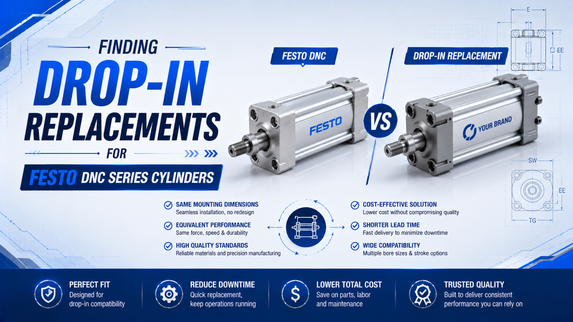
A Festo DNC replacement is genuinely drop-in only when the exact configured cylinder fits the installed mechanical interfaces and passes the machine’s functional checks. Bore and stroke are the starting point. The complete DNC suffix, mounting, ports, rod end, sensors, cushioning, operating limits, and first-article results decide whether the replacement can be released.
There are two practical routes. The first is Festo’s DSBC successor family. The second is an ISO 15552 cylinder from another manufacturer. Neither route should be approved from a cross-reference number alone.
Key Takeaways
- ISO 15552 covers 32-320 mm bores at a maximum rated pressure of 10 bar.
- Decode every DNC suffix before comparing replacements.
- Verify dimensions, configured interfaces, functional duty, and first-article results separately.
- Freeze the approved drawing and part code for future orders.
In this guide
- What Does “Drop-In” Mean for a Festo DNC Replacement?
- Is Festo DSBC the Official Successor to DNC?
- How Do You Decode a DNC Part Number Correctly?
- Which Dimensions and Interfaces Must Match?
- How Do You Verify Force, Speed, Cushioning, and Sensors?
- Evidence Required from a Third-Party Supplier
- Replacement Approval Workflow
- Festo DNC Replacement FAQs
What Does “Drop-In” Mean for a Festo DNC Replacement?
A drop-in replacement must pass dimensional, configured-interface, functional, and release checks. ISO 15552:2018 defines basic, mounting, and accessory dimensions for detachable-mount cylinders from 32 to 320 mm bore at a maximum rated pressure of 1,000 kPa, or 10 bar. It does not standardize every product option (ISO 15552:2018).
Drop-in replacement means the proposed configured cylinder can be installed through the existing interfaces and meet the machine’s approved operating requirements without an unreviewed mechanical, pneumatic, electrical, or control change.
Use four separate approval layers:
| Layer | Question | Evidence |
|---|---|---|
| Dimensional fit | Will the cylinder and mounting fit the existing envelope? | Current drawings, controlled measurements, and CAD overlay |
| Configured interfaces | Will ports, rod hardware, sensors, and cushions connect and remain accessible? | Complete part-code decode and option-specific data |
| Functional equivalence | Will force, timing, impact control, leakage, and sensing meet the duty? | Application data and defined test results |
| Released configuration | Can purchasing order the same approved unit again? | Frozen part number, drawing revision, first-article report, and change control |
ISO compliance is evidence for the dimensions within the standard’s scope. It is not evidence that two cylinders share the same port orientation, seal material, temperature range, cushion behavior, piston magnet, switch, or catalog stroke offering.
The detailed ISO 15552 interchangeability guide covers the generic four-layer method. This article applies that method to the Festo DNC code, its DSBC successor path, and third-party cross-reference requests.
The safest cross-reference is not one line that equates two part numbers. It is an interface ownership record that shows which requirements come from ISO 15552, which come from the exact DNC configuration, and which belong to the machine acceptance test.
Is Festo DSBC the Official Successor to DNC?
Yes. Festo identifies DSBC as the successor to 2 earlier series, DNC and DNCB, and says its ISO 15552-compliant dimensions allow replacement of preceding products. That establishes the intended path, but the exact cushioning, sensing, ports, rod, environmental limits, and mounting options still require confirmation (Festo DSBC overview).
For example, Festo’s own purchasing guide mapped part number 163410, DNC-63-320-PPV-A, to part number 1383641, DSBC-63-320-PPSA-N3. That is a manufacturer-issued mapping for those exact codes, not a universal rule that every DNC suffix converts to one DSBC suffix (Festo purchasing guide).
Pay close attention to cushioning. A DNC code containing PPV specifies adjustable pneumatic cushioning at both ends. A mapped DSBC may contain PPS, Festo’s self-adjusting pneumatic cushioning. Both are end-position cushioning methods, but they do not have identical adjustment behavior.
Choose the successor path in this order:
- Record the complete DNC part number and Festo part number.
- Check Festo’s current product data or successor reference for that configuration.
- Compare the two option-specific drawings and technical data.
- Identify every changed feature, including cushioning and sensor provision.
- Decide whether the change is acceptable for the actual moving mass, speed, environment, and control sequence.
- Validate the selected DSBC configuration on the machine before routine release.
Festo still published a DNC product-range document dated April 2026, while a regional Festo notice describes a 2026 phase-out of DNC special variants. Availability should therefore be checked at the exact part-number level instead of labeling the whole family as either current or discontinued (Festo DNC 2026 catalog, Festo special-variant notice).
How Do You Decode a DNC Part Number Correctly?
Decode the code from current Festo data rather than expanding the letters by guesswork. In DNC-63-320-PPV-A, the numbers mean a 63 mm piston and 320 mm stroke, PPV means adjustable pneumatic cushioning at both ends, and A means position sensing via a proximity sensor (Festo data sheet 163410).
The base pattern is:
DNC - piston diameter - stroke - cushioning - options
| Code element | Meaning in the example | Replacement consequence |
|---|---|---|
| DNC | Standards-based, double-acting profile cylinder family | Identify the correct dimensional and accessory family |
| 63 | 63 mm piston diameter | Controls piston area, force, mounting dimensions, ports, and rod size |
| 320 | 320 mm stroke | Controls travel and overall extended and retracted length |
| PPV | Adjustable pneumatic cushioning at both ends | Match or formally review the replacement cushion behavior |
| A | Position sensing via proximity sensor | Confirm magnetic sensing provision and compatible switch arrangement |
Other DNC options can change the replacement substantially. Festo’s DNC catalog identifies examples such as Q for protection against rotation, S2 for a through piston rod, K2 for an extended male rod thread, K3 for a female rod thread, and K5 for a special rod thread. Special-function DNC-KP, DNC-EL, DNC-V, and DNCT variants are not equivalent to a basic DNC body.
A missing suffix is not a minor purchasing omission. It can hide a female thread, through rod, anti-rotation feature, position-sensing requirement, special seal, or integrated function. Preserve the complete code even when the nameplate is damaged by using the old drawing, invoice, machine bill of materials, and photographs.
Which Dimensions and Interfaces Must Match?
Compare the exact option-specific drawings, not generic family outlines. For DNC-63-320-PPV-A, Festo lists a 63 mm piston, 320 mm stroke, M16x1.5 external rod thread, G3/8 pneumatic connection, 22 mm PPV cushioning length, and proximity-sensor provision. Those values do not automatically apply to another bore or suffix (Festo data sheet 163410).
Use a controlled comparison sheet with one row for each interface:
| Interface | What to compare | How to verify |
|---|---|---|
| Mounting | Face dimensions, hole pattern, threads, pins, bracket width, and centerline | ISO table where applicable, supplier drawings, and first-article measurement |
| Stroke and length | Nominal travel, retracted length, extended length, and rod projection | Drawing overlay and measured travel |
| Rod end | Diameter, thread designation, gender, usable thread length, and wrench flats | Drawing callout, thread gauge, and mating accessory |
| Air ports | Thread, sealing method, location, fitting clearance, and tube route | Port callout, gauge, and installation check |
| Sensors | Magnetic piston, slot or bracket, switch model, output, connector, and cable path | Switch data and guarded motion test |
| Cushioning | Cushion type, adjustment access, permissible moving mass, speed, and impact behavior | Exact product data and loaded stroke test |
| Accessories | Flange, foot, clevis, trunnion, pins, nuts, and rod attachment | Accessory part numbers and assembly drawing |
| Environment | Temperature, corrosion, lubricant, contamination, washdown, and restricted substances | Option-specific material and environmental data |
Do not infer bore by measuring the body outside diameter. Profile shape and wall construction vary. Decode the nameplate or catalog first. If identity remains uncertain, use controlled disassembly or manufacturer records rather than turning an external body measurement into a nominal bore.
Likewise, do not invent a universal mounting tolerance such as ±0.1 mm. The acceptance limit must come from ISO 15552 where the dimension is standardized, the machine drawing, the supplier’s controlled drawing, or a justified assembly requirement.
The piston rod end thread guide helps distinguish thread designation, gender, usable engagement, and mating hardware. Those details matter when the existing clevis or coupling must be reused.
How Do You Verify Force, Speed, Cushioning, and Sensors?
Check the machine duty after fit. Festo lists theoretical forces of 1,870 N advancing and 1,682 N retracting at 6 bar for DNC-63-320-PPV-A, plus 0.5 J permissible impact energy at the end positions. These catalog values describe that configuration under stated conditions, not guaranteed machine output (Festo data sheet 163410).
Calculate theoretical extension force from effective pressure and full piston area:
Retraction force uses the annular area:
Here, is theoretical force in newtons, is effective cylinder pressure in pascals, is bore diameter in metres, and is rod diameter in metres. Real output is lower because pressure drops during motion and seals, guides, and load geometry create losses.
Use the pneumatic cylinder force calculator to compare extension and retraction force with measured point-of-use pressure. Retain the application’s accepted force margin rather than assuming that equal nominal bore proves equal performance.
Speed depends on the complete air path. Compare valve flow, tube inside diameter and length, fittings, exhaust restrictions, load, and cushion setting. A replacement with the correct dimensions can still miss cycle time when its port or cushion arrangement changes.
For cushioning, test the actual moving mass and normal operating speed. Start conservatively, then adjust under controlled motion. Do not use a generic percentage for impact reduction. The replacement passes only when end impact, rebound, vibration, noise, and cycle time remain within the machine’s approved limits.
For sensors, confirm both the cylinder provision and the installed switch. Match switch technology, voltage, PNP or NPN output where applicable, normally open or closed logic, connector, cable, mounting position, and PLC input behavior. The reed and Hall-effect sensor guide explains why physical groove fit alone does not prove electrical compatibility.
A functional replacement comparison should retain the old cylinder’s normal operating baseline. Pressure during motion, stroke time, cushion setting, end impact, leakage, and sensor switching position are more useful than testing the new cylinder against an undefined idea of “equivalent performance.”
Evidence Required from a Third-Party Supplier
Require configuration evidence before accepting a third-party cross-reference. ISO 10099:2001 is a 4-page standard covering final functional examination and acceptance criteria for double-acting, single-rod pneumatic cylinders. It supports functional acceptance, while ISO 15552 supplies the dimensional reference. Neither standard validates an undocumented supplier claim by itself (ISO 10099:2001).
Send the supplier the installed DNC code, Festo part number, nameplate photos, current drawing, machine position, mounting accessories, sensor model, pressure, load direction, stroke time, environment, and acceptance criteria. Ask for an exception list instead of a simple “yes, compatible.”
The supplier should return:
- Exact configured replacement part number
- Option-code explanation
- Dimensioned drawing for the offered bore, stroke, rod, ports, and mounting
- CAD file suitable for overlay
- Technical limits for pressure, temperature, speed, cushioning, impact, and environment
- Material and seal information required by the application
- Sensor provision and compatible switch details
- Manufacturing and inspection location
- First-article measurement plan
- Functional test method and results
- Traceability and drawing revision
- Written change-notification conditions
Use the ISO 15552 procurement checklist when building the RFQ. It separates dimensions controlled by the standard from configured product options and machine requirements.
Reject blanket language such as “100% compatible with all DNC cylinders.” A credible cross-reference names the exact installed code, proposed code, matched interfaces, deviations, limits, test method, and approval status.
For reliability claims, request the test method, sample count, failure definition, conditions, and reporting basis. ISO 19973-3 specifies methods for assessing rod-cylinder reliability and reporting results; it does not support an unsourced universal cycle-life promise (ISO 19973-3:2015).
Replacement Approval Workflow
Release the replacement through 5 gates: identify, compare, isolate, install, and validate. OSHA 29 CFR 1910.147 covers servicing where unexpected startup or stored-energy release could injure workers, and OSHA explicitly includes pneumatic energy. The employer’s energy-control procedure therefore comes before cylinder removal or test installation (OSHA).
Gate 1: Identify
Record the complete code, part number, machine position, failure mode, installation photographs, accessory numbers, and baseline operating data. Keep the old cylinder available until the replacement passes.
Gate 2: Compare
Approve the drawing overlay and interface sheet. Resolve every exception involving mounting, overall length, rod end, ports, sensors, cushions, seals, and environment before purchase.
Gate 3: Isolate
Follow the site’s lockout/tagout process. Shut off and lock the air source where required, vent downstream pressure, restrain gravity or stored mechanical loads, and verify the zero-energy state before disconnecting tubes, sensors, or mounts.
Gate 4: Install
Mount the cylinder without forcing alignment. Confirm fittings and cables clear adjacent equipment. Begin with conservative speed and cushion settings, then use guarded motion to establish normal operation.
Gate 5: Validate and freeze
Record fit, stroke, leakage, pressure during motion, extension and retraction time, sensor switching, cushion behavior, end impact, and restart behavior. Release the replacement only after all acceptance limits pass.
Freeze the approved supplier, part number, drawing revision, accessory set, inspection record, and machine-trial result. Any later change to the body, rod, seal, magnet, cushion, site, or critical sub-tier source should return to the applicable approval gate.
Festo DNC Replacement FAQs
These 5 answers separate an official successor mapping from third-party interchangeability. ISO 15552 covers dimensions for 32-320 mm bores at 10 bar, while Festo’s exact DNC data defines the selected ports, rod end, cushioning, sensing, and operating limits. Both evidence layers are needed before machine validation (ISO 15552:2018).
Is a Festo DSBC always a drop-in replacement for DNC?
No. DSBC is Festo’s official successor family, and Festo provides mappings for specific DNC codes. Confirm the exact DSBC part number, cushioning option, sensor provision, ports, rod end, mounting, environmental limits, and accessories. Then compare drawings and run the machine acceptance test before routine release.
Can another brand’s ISO 15552 cylinder replace a Festo DNC?
It can, provided the proposed configuration passes dimensional, interface, functional, and first-article checks. ISO 15552 covers a 32-320 mm dimensional series, not every supplier option. Compare the complete drawings, ports, rod end, sensors, cushioning, materials, pressure, speed, and acceptance evidence before calling it drop-in.
What does PPV-A mean in a Festo DNC code?
In a code such as DNC-63-320-PPV-A, PPV means adjustable pneumatic cushioning at both ends and A indicates position sensing via a proximity sensor. It does not describe a double-ended piston rod or rod-thread variant. Preserve every suffix when requesting the replacement.
Can I reuse the existing Festo sensors and accessories?
Only after checking the exact sensor and accessory part numbers. A replacement may share ISO 15552 mounting dimensions yet use a different sensor slot, magnet, switch position, connector, cushion access, or accessory geometry. Verify physical fit, electrical logic, cable clearance, switching position, and guarded operation.
What should a supplier provide before I order a DNC alternative?
Request the exact replacement code, option decode, controlled drawing, CAD overlay, deviation list, technical limits, material information, sensor details, first-article plan, test results, traceability, and change-notification terms. ISO 10099 provides functional acceptance criteria, but the supplier must connect those tests to the offered configuration and your application.
Sources and technical references
- Festo DNC-63-320-PPV-A data sheet, exact code, dimensions, connections, force, cushioning, and sensing
- Festo DNC 2026 product-range catalog, DNC variants and option structure
- Festo DSBC successor overview, official DNC and DNCB successor relationship
- Festo DNC to DSBC purchasing guide, exact part-number examples
- ISO 15552:2018, dimensional interchangeability scope
- ISO 10099:2001, cylinder final examination and acceptance criteria
- ISO 19973-3:2015, rod-cylinder reliability assessment and reporting
- OSHA control of hazardous energy, pneumatic energy and servicing safety