

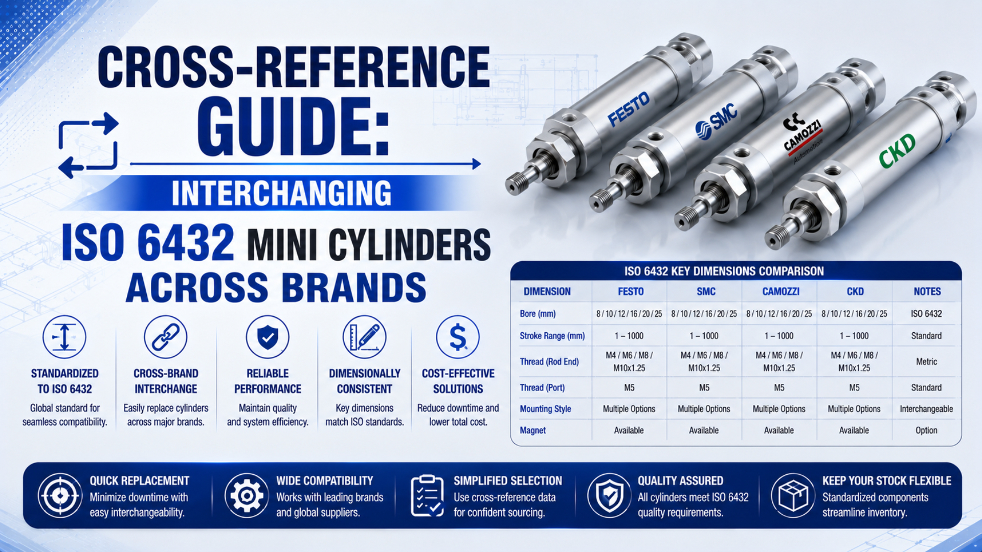
An ISO 6432 label narrows the search for a replacement mini cylinder, but it does not prove that two complete part numbers are interchangeable. Use the standard to screen the mounting envelope. Then compare the full model code, current manufacturer drawings, rod end, ports, sensors, cushioning, materials, and operating limits.
An ISO 6432 cylinder cross reference is a documented comparison between an installed cylinder and a proposed substitute. This guide identifies the official ISO 6432 product families from seven manufacturers and shows how to turn a series-level match into a controlled replacement decision without declaring exact equivalents before the configured drawings are reviewed.
Key Takeaways
- ISO 6432:2015 covers 8-25 mm bore cylinders rated up to 1,000 kPa.
- A series match is only the first gate; suffixes can change action, cushioning, sensors, materials, and interfaces.
- Approve a replacement from two configured drawings and a machine test, not from bore and stroke alone.
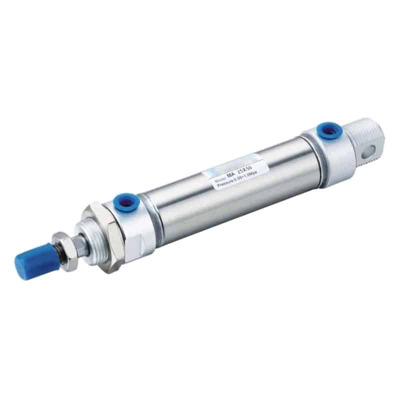
A round-body mini cylinder may belong to an ISO 6432 family, but the complete model code and configured drawing still control the replacement.
In this guide
- What does ISO 6432 actually standardize?
- Which official ISO 6432 families do major brands offer?
- ISO 6432 cylinder cross reference: why bore and stroke are not enough
- Model-code suffixes control the ordered cylinder
- What belongs in a defensible cross-reference sheet?
- When does a replacement become an engineered change?
- How should the replacement be approved on the machine?
- ISO 6432 Cross-Reference FAQs
What Does ISO 6432 Actually Standardize?
ISO 6432:2015 establishes metric mounting dimensions needed for interchangeability for single-rod pneumatic cylinders with 8-25 mm bores and a maximum rated pressure of 1,000 kPa, or 10 bar. The standard also preserves design freedom, so conformity does not make every internal feature or configured interface identical (ISO, 2015).
That distinction is the foundation of a reliable cross-reference. ISO 6432 provides a common dimensional framework for a family of compact round-body cylinders. It does not certify that every order code has the same port thread, rod-end configuration, magnetic sensing, cushioning, seal material, corrosion resistance, allowable side load, or service life.
The practical reading is:
| Evidence level | What it tells you | What it does not prove |
|---|---|---|
| ISO 6432 standard | Governing cylinder family and specified mounting dimensions | Exact equivalence between two part numbers |
| Manufacturer conformity statement | A named series is designed to the standard | Every suffix has the same features as another brand |
| Configured product drawing | Dimensions and interfaces for one complete model | Performance in the installed machine |
| Machine acceptance record | Fit and behavior in the real application | Suitability for a different load, environment, or control sequence |
Treat ISO conformity as a boundary condition, not a purchasing conclusion. It removes some dimensional uncertainty, but the configured drawing and application requirements close the remaining gaps.
Which Official ISO 6432 Families Do Major Brands Offer?
Seven current first-party catalogs identify the relevant ISO 6432 families: Festo DSNU, SMC C85, Parker P1A/P1S, Norgren RM/8000 and KM/8000, Camozzi 16/23/24/25, AirTAC MI/MIC, and Bepto MA/MA6432. These names locate the correct catalog family; they do not declare one-to-one model equivalence (Festo, SMC, Parker).
| Manufacturer | Official ISO 6432 family | Useful first-party evidence | Cross-reference caution |
|---|---|---|---|
| Festo | DSNU family | Festo DSNU catalog identifies ISO 6432 models and multiple design variants | DSNU suffixes distinguish cushioning, sensing, rod, material, and other options |
| SMC | C85 | SMC ISO 6432 catalog identifies C85 as the ISO 6432 family | CJ2/CDJ2 is not the series to use for an ISO 6432 cross-reference |
| Parker | P1A and P1S | Parker P1A catalog and Parker P1S catalog identify Mini ISO 6432 cylinders | P1D and P1F belong to different product contexts and should not be substituted as family names |
| Norgren | RM/8000 and KM/8000 | Norgren RM/8000 product data states conformity to ISO 6432 | Bore, port, magnetic piston, cushioning, seal, and material options vary by model |
| Camozzi | Series 16, 23, 24, and 25 | Camozzi minicylinder catalog identifies the ISO 6432 families | Series 61 is an ISO 15552 family, not the mini-cylinder family in this guide |
| AirTAC | MI and MIC | AirTAC MI/MIC product data identifies ISO 6432 conformity | MAL should not be treated as the ISO 6432 family without model-specific evidence |
| Bepto | MA and MA6432 | MA/MA6432 product data lists 8, 10, 12, 16, 20, and 25 mm MA6432 bores | Confirm the exact kit or assembled-cylinder code and drawing before replacing another brand |
This table answers “which catalog should I open?” It cannot answer “which complete part number should I buy?” A family may contain single-acting and double-acting versions, different piston-rod threads, several cushioning methods, magnetic and non-magnetic pistons, or material variants.
The safest cross-reference starts with a negative rule: if a proposed brand family is not explicitly identified as ISO 6432 in current first-party documentation, do not let a distributor spreadsheet promote it into the candidate set.
ISO 6432 Cylinder Cross Reference: Why Bore and Stroke Are Not Enough
ISO 6432 covers six nominal bore sizes from 8 to 25 mm, yet a shared bore and stroke still leave several machine interfaces unresolved. A 16 mm by 100 mm description identifies piston diameter and travel only; it does not define retracted length, rod thread, port arrangement, sensing, cushioning, or materials (ISO, 2015).
Compare these items before calling two cylinders interchangeable:
| Check group | Record from the installed cylinder | Verify on the candidate drawing |
|---|---|---|
| Motion | Single-acting or double-acting, spring direction, required stroke | Action type, stroke tolerance, end positions |
| Mounting | Nose thread, rear eye or clevis, pin size, bracket geometry | Mounting dimensions, pin diameter, accessory code |
| Rod end | Male or female, thread size and pitch, usable length, shoulder | Thread designation, length or depth, rod-end option |
| Body envelope | Retracted length, extended length, body diameter, wrench clearance | Configured dimensions for the selected stroke |
| Pneumatic ports | Thread standard, size, orientation, fitting clearance | Port callout and usable surrounding space |
| Sensing | Magnetic piston, switch model, groove, cable and connector | Compatible sensor family, output type and switching position |
| Motion control | Cushion type, flow-control location, permitted speed | Cushion option, speed range and adjustment access |
| Service conditions | Dynamic pressure, temperature, medium, washdown, chemicals | Rated pressure, temperature, materials and environmental limits |
A rod-end mismatch can stop assembly even when the mounting body fits. A wrong pneumatic thread can damage a port or misdirect a fitting, so verify it with the guide to cylinder port thread types. The same applies to an incompatible reed switch or Hall-effect sensor. Use the detailed guides to cylinder piston rod end thread types and cylinder reed switch and Hall-effect sensor operation when those interfaces are uncertain.
Could an adapter solve the problem? Sometimes, but the adapter changes installed length, alignment, clearance, or load transfer. That moves the work out of a like-for-like replacement and into an engineered change.
Model-Code Suffixes Control the Ordered Cylinder
Festo’s DSNU documentation covers 8-25 mm ISO 6432 cylinders while separating variants for construction, cushioning, sensing, and rod features. That catalog structure illustrates a general rule: the series prefix selects the family, but the suffixes define the ordered cylinder that must be compared (Festo).
Work from the complete code, including characters after the bore and stroke. If the nameplate is damaged, search maintenance records, purchase orders, machine bills of material, archived drawings, and the manufacturer’s configured CAD data. Do not reconstruct a suffix from appearance alone.
Decode in this order:
- Series: Confirm that the manufacturer identifies the family as ISO 6432.
- Bore and stroke: Match both values, then check whether the stroke is a catalog standard, a manufacturer-configured increment, or a special build with different overall-length consequences.
- Action: Identify single-acting, double-acting, spring-return, or spring-extend behavior.
- Cushioning: Record elastic, fixed, adjustable, or other catalog options.
- Piston sensing: Confirm magnetic or non-magnetic construction and the approved switch family.
- Rod configuration: Verify external or internal thread, pitch, length, material, and special rod options.
- Seal and material options: Match temperature, chemical, corrosion, lubrication, and cleanliness needs.
- Mounting and accessories: Identify brackets, clevises, pins, nuts, and sensor clamps by their own order codes.
In our experience, one missing suffix can produce a cylinder that bolts into place but never sends the expected end-position signal. Freezing the full old and new codes in the approval record is faster than troubleshooting an apparently “identical” cylinder after installation.
When the code cannot be recovered, build a measured replacement specification. The companion step-by-step ISO 6432 cylinder replacement guide covers photographs, measurements, force, speed, lockout, installation, and acceptance testing in detail.
What Belongs in a Defensible Cross-Reference Sheet?
A defensible sheet needs at least four evidence layers: the exact old code, the exact proposed code, current configured drawings, and a documented machine test. ISO 6432 itself is only six pages, so the manufacturer documents and application record must carry the product-specific details that the standard intentionally leaves open (ISO, 2015).
Use one row for every interface or operating requirement:
| Field | Existing cylinder | Candidate cylinder | Evidence | Status |
|---|---|---|---|---|
| Manufacturer and full code | Exact code, including suffixes | Exact code, including suffixes | Nameplate, order record, catalog | Match / deviation |
| ISO family claim | Series and edition referenced | Series and edition referenced | Current first-party catalog | Confirmed / not confirmed |
| Bore and stroke | Nominal values | Nominal values | Configured drawing | Match / deviation |
| Mounting dimensions | Dimension symbols and values | Dimension symbols and values | Two drawings at same revision level | Match / deviation |
| Rod end | Gender, size, pitch, length, shoulder | Same fields | Drawing and thread inspection | Match / deviation |
| Ports | Thread, size, orientation, clearance | Same fields | Drawing and fitting review | Match / deviation |
| Sensors | Piston magnet, switch, output, connector | Same fields | Switch datasheets and circuit record | Match / deviation |
| Cushioning | Type and adjustment access | Type and adjustment access | Model code and catalog | Match / deviation |
| Operating limits | Pressure, temperature, speed, medium | Rated limits | Datasheet and measured application | Pass / fail |
| Materials and compliance | Required materials and certificates | Offered materials and certificates | Supplier documents | Pass / fail |
| Machine result | Baseline cycle and alarm behavior | Test result | Approved acceptance record | Pass / fail |
Record document titles, revision dates, URLs or controlled file references. A statement such as “the dimensions look the same” is not traceable. A pair of marked drawings with each interface signed off is.
If purchasing needs a shorter document, keep the technical sheet as the controlled source and issue a one-page approved-equivalent list from it. The short list should never become the only evidence.
When Does a Replacement Become an Engineered Change?
A replacement becomes an engineered change as soon as it alters a controlled interface or machine behavior. ISO 6432 allows manufacturer design freedom, so a conforming candidate can still require a new bracket, fitting, sensor, program value, pressure setting, safety review, or compliance record (ISO, 2015).
Stop the like-for-like process when any of these conditions appears:
- A bracket needs drilling, slotting, shimming, bending, or welding, because the mounting load path and alignment are no longer the approved original arrangement.
- A rod adapter changes the closed length, articulation, or load path.
- A port adapter interferes with the frame or changes tube routing.
- The existing sensor cannot be used in the candidate groove.
- The PLC switching position, timing window, or logic must change, including a change made only to accommodate a different sensor location.
- Cushioning or speed control behaves differently at the required load.
- The candidate requires a different operating pressure.
- Seal, lubricant, material, or surface changes affect the environment.
- A certificate, validation record, or safety assessment no longer applies.
The change may still be acceptable. It simply needs the owner, drawing revision, risk review, and test depth appropriate to the machine. Calling it “interchangeable” should not be used to bypass that process.
For a simple production axis, the review may be a maintenance change record plus engineering approval. For a guarded vertical load, food-contact area, validated process, or safety-related function, involve the responsible safety, quality, and compliance personnel before ordering.
How Should the Replacement Be Approved on the Machine?
Approval should cover fit, leakage, full stroke, sensing, dynamic pressure, cycle time, end impact, restart behavior, and the real load. OSHA treats pneumatic pressure as hazardous energy during servicing, so installation and testing must follow the site’s energy-control procedure before any performance comparison begins (OSHA, accessed 2026).
Use the cross-reference sheet to define the test before the new cylinder arrives. Record the baseline where possible. Then install under the machine’s approved lockout and stored-energy controls, begin at a controlled speed, and restore normal operating conditions only after alignment and sensor checks pass.
If the candidate has a different rod diameter or the application pressure is uncertain, review the direction-specific method for calculating force from pressure and piston area before the machine test. A dimensional cross-reference should never conceal a loss of usable extension or retraction force.
Minimum acceptance record:
- Confirm mounting surfaces seat without force or distortion.
- Verify rod alignment through the complete stroke.
- Leak-check ports, fittings, rod seal, and end connections.
- Confirm both end positions under normal load, including the direction that has the smaller force margin or the tighter machine timing window.
- Record sensor switching and PLC input behavior.
- Measure dynamic pressure during the motion that matters.
- Compare extend and retract times with the approved baseline, then investigate any difference before compensating with pressure or flow-control adjustments.
- Check cushioning, noise, bounce, and hard impact.
- Inspect tube, cable, fitting, and adjustment-screw clearance.
- Run the required restart and fault-recovery sequence.
Don’t convert a series-level cross-reference into a facility-wide approved substitute after one installation. Freeze the exact pair of model codes, drawing revisions, machine position, deviations, and test results. Reuse that approval only inside the same documented boundary.
ISO 6432 Cross-Reference FAQs
ISO 6432:2015 applies to six bore sizes from 8 through 25 mm and a maximum rated pressure of 1,000 kPa. Those limits help identify the standard family, while the answers below clarify what must still be checked at the configured-model and machine levels (ISO, 2015).
Are all ISO 6432 cylinders directly interchangeable?
No. ISO 6432 establishes basic and mounting dimensions needed for interchangeability, but it allows manufacturers design freedom. Two cylinders still require comparison of their complete codes, configured drawings, action, rod end, ports, sensors, cushioning, materials, operating limits, installation envelope, and machine acceptance results before they can be approved as substitutes.
Can I cross-reference a cylinder from bore and stroke alone?
No. Bore and stroke identify piston size and travel, not the complete interface. Record retracted and extended lengths, mounting, rod thread and usable length, port type and position, sensor system, cushioning, materials, pressure, temperature, load, speed, and environmental requirements before selecting a candidate part number.
Which SMC series should be used for an ISO 6432 comparison?
Use SMC’s C85 family as the ISO 6432 starting point. Do not substitute CJ2 or CDJ2 merely because those are small round cylinders. After identifying C85, compare the full configured code and drawing against the installed cylinder, including action, mounting, rod end, sensing, cushioning, and operating limits.
Do ISO 6432 cylinders use identical sensors and mounting accessories?
Not necessarily. Sensor groove geometry, switch model, cable, connector, electrical output, piston magnet, brackets, clevises, pins, and nuts can vary by manufacturer or option. Verify each accessory separately and confirm that the sensor switches at the required machine position without changing the approved control sequence.
What should I send a supplier for a reliable cross-reference?
Send the full old model code, nameplate and installation photos, both mounting ends, bore, stroke, rod-end details, ports, fittings, sensors, working pressure, load direction, cycle target, environment, and current drawings. Ask for the complete proposed code, configured drawing, deviations, datasheet, accessory list, and applicable compliance documents in return.
Sources and technical references
- ISO 6432:2015, Pneumatic Fluid Power, Single Rod Cylinders, 1,000 kPa Series
- Festo DSNU ISO Cylinder Documentation
- SMC ISO Cylinders, ISO 6432 C85 Series
- Parker P1A Mini ISO 6432 Round-Body Cylinders
- Norgren RM/8000/M ISO Roundline Cylinder
- Camozzi Series 16, 23, 24, and 25 Minicylinders
- AirTAC MI/MIC ISO 6432 Mini Cylinder
- OSHA Control of Hazardous Energy