

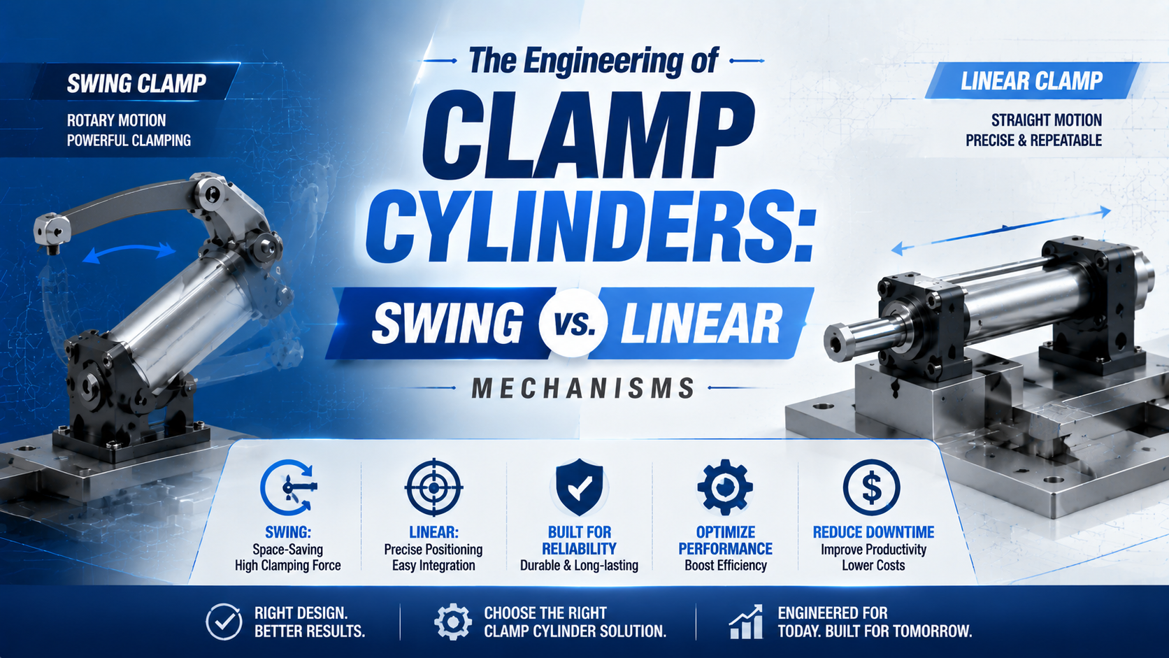
Swing and linear clamp cylinders solve different fixture problems. A swing clamp rotates its arm away from the loading area, then uses a short linear stroke to press the workpiece against its supports. A direct linear clamp moves along one axis. Choose between them by tracing clearance, force, reaction load, and the required safe state.
The distinction sounds simple, but catalog names can blur it. A swing clamp isn’t an angular gripper, and a direct-acting clamp isn’t automatically a power clamp. The useful comparison begins at the workpiece, not at the cylinder bore.
Key Takeaways
- A Festo CLR combines a 90° swing with a 10-50 mm clamping stroke.
- A 25 mm CLR produces 188 N effective force at 6 bar with its clamp finger.
- Clamp-pad force depends on pressure, arm geometry, support position, and product limits.
- Loss of air pressure requires a defined, risk-assessed machine response.
What Is the Fundamental Difference Between Swing and Linear Clamp Cylinders?
Festo specifies a 90° swivel angle and a separate 10-50 mm linear clamping stroke across its CLR range (Festo CLR datasheet, 2014). A swing clamp therefore clears the loading zone before pressing down, while a direct linear clamp approaches and clamps along one straight path.
A swing clamp cylinder is a linear/swivel unit whose piston rod follows a guided helical path during part of the stroke, rotating the clamp arm to or from the workpiece. Once the arm reaches the clamping orientation, the remaining piston movement is linear. That final movement, not the rotation, creates the intended clamp load.
A direct linear clamp is an actuator or straight-line clamping module that applies force along one axis. It needs an unobstructed approach path, but it doesn’t sweep an arm through the fixture. This can simplify force direction and sensing when the workpiece can be loaded from another side.
Several related devices need separate treatment:
| Device | Output motion | Main engineering question |
|---|---|---|
| Linear/swivel clamp | Rotation followed by linear clamp stroke | Does the arm clear the part and stay within its force and moment limits? |
| Direct linear clamp | Straight approach and return | Is there enough axial clearance, guidance, and structural support? |
| Power or toggle clamp | Linkage motion with geometry-dependent force | What force does the manufacturer rate at the selected arm length and angle? |
| Pneumatic gripper | Opposed jaw motion | Can jaw force and friction retain a handled part? |
| Pin clamp | Locates or clamps through a hole | Do the hole tolerance, locating function, and withdrawal path fit? |
This taxonomy matters. If opposed jaws hold a loose component for transfer, use gripper calculations. If a clamp arm pushes a workpiece into fixture locators, analyze the fixture reactions. For a broader motion comparison, see linear vs. rotary actuators.
The word “swing” describes clearance motion, not a promise of force multiplication. Treating it as a lever category leads to the wrong cylinder, arm, and fixture calculations.
How Does a Pneumatic Swing Clamp Complete Its Motion?
The Festo CLR total stroke is the sum of its swivelling stroke and clamping stroke, and the range operates from 2 to 10 bar (Festo CLR datasheet, 2014). The arm must complete its clearance rotation before the final axial movement loads the workpiece.
A normal clamping sequence is:
- The workpiece enters while the arm is retracted and rotated clear.
- The piston advances through its guided swivel portion.
- The arm reaches its specified angular position above the clamp pad.
- The piston travels through the linear clamping stroke.
- The pad pushes the workpiece into the fixture supports and locators.
- On release, the axial load comes off before the arm swings away.
The arm should not drag across the workpiece during rotation. Contact in the swing phase can scratch the part, generate an unintended side load, shift the workpiece before it reaches its locators, or jam the guide. What happens when the part sits slightly high? The fixture still needs enough vertical clearance to complete rotation without contact.
Swing direction also matters. Left-hand and right-hand versions can share the same cylinder envelope yet sweep through different machine space. Check the full arm, bolt head, pad, tubing, sensor cable, cutter, robot gripper, and operator loading path at both end positions. A top-view arc alone won’t reveal every collision.
Flow control changes motion time, but it doesn’t redefine the allowable arm. Festo requires custom fingers to stay within pressure-dependent arm-length limits and specifies permissible force and torque values (Festo CLR technical data, 2014). If a fast cycle demands a custom arm, verify its length, mass, center of gravity, and permitted dynamic loading before increasing speed.
Clamp Force From Cylinder to Pad
At 6 bar, Festo lists 227 N theoretical force for its 25 mm CLR but only 188 N effective force with the clamp finger, measured 5 mm before the end of stroke (Festo CLR datasheet, 2014). That 17% difference shows why a universal swing-force multiplier is invalid.
For a plain piston acting on its full bore area, begin with:
Here, is piston area in square metres and is bore diameter in metres. The ideal pressure-area result must then be adjusted for the real pressure differential and losses:
In this equation, is usable axial cylinder force in newtons, is the pressure difference across the piston in pascals, and represents seal friction and other specified losses. Use annular area instead of full bore area when the rod side generates the clamp stroke.
The ideal extension figures below use 6 bar gauge pressure and ignore friction, pressure drop, back pressure, and product-specific restrictions:
| Bore | Piston area | Ideal force at 6 bar | What it does not prove |
|---|---|---|---|
| 32 mm | 804 mm² | 483 N | Effective pad force or arm capacity |
| 50 mm | 1,963 mm² | 1,178 N | Fixture holding capacity |
| 80 mm | 5,027 mm² | 3,016 N | Safe dynamic load during rotation |
| 100 mm | 7,854 mm² | 4,712 N | Force from a toggle or power clamp |
Never multiply that table by 4 merely because an arm swings. For a manufacturer-supplied swing finger, use the published effective-force table and allowable arm-length curve. For a power clamp, use its rated clamp-force curve at the specified bore, pressure, arm length, and closing angle. For a custom linkage, analyze every pivot and loss separately.
The Cylinder Force Calculator can check the pressure-area step. If the load is known but the bore isn’t, the Cylinder Bore Size Calculator provides a starting bore estimate. Neither tool replaces the clamp manufacturer’s arm curve or a fixture-level force balance.
Fixture Load Paths and Clamp Placement
Carr Lane models a free workpiece with 12 possible directions of movement and explains that locators establish position before clamps hold the part against them (Carr Lane locating and clamping principles, retrieved July 19, 2026). The clamp should direct force into a locator or supported, stiff region rather than bend the workpiece.
Locators establish the datum. Supports carry the primary reaction. Clamps keep the part seated. A clamp cylinder can be repeatable and still produce inaccurate parts if its pad pushes into an unsupported wall or if the clamping direction lifts the workpiece away from a locator.
For a simple arm, the bending moment at its root is:
Here, is arm-root moment in newton-metres, is the force at the pad in newtons, and is the perpendicular distance from the load line to the arm support in metres. Doubling arm length doubles moment for the same pad force. It can also increase deflection and inertia.
The complete fixture needs an equilibrium check around its locating and support points. Include cutting forces, tool-entry and tool-exit loads, gravity, robot acceleration, weld distortion, and any ejection force. Friction can help, but it shouldn’t silently replace positive reaction surfaces when slip has serious consequences.
A larger clamp cylinder can make a weak fixture less accurate. More force applied away from a support increases part distortion and frame opening, so “more newtons” isn’t automatically a safer correction.
Place pads above solid supports whenever possible, and avoid asking the actuator rod or swivel guide to absorb external guidance loads. If the approach is misaligned, review side-load mitigation for linear cylinders before releasing the fixture design.
What Space and Mounting Constraints Change the Decision?
DESTACO’s 8116 swing clamp has 0.85 in total stroke, of which 0.47 in occurs during rotation, and it is rated for 18 lbf at 5 bar (DESTACO 8116, retrieved July 19, 2026). Those values show that swing clearance and final clamp travel are separate envelope checks.
A swing clamp usually wins when the operator or robot needs open access above the clamping point. Its body can sit close to the fixture, but the rotating arm needs a three-dimensional swept volume. Check that volume with the longest permitted arm and the actual pad, not with the bare cylinder model.
A direct linear clamp avoids the side sweep. It may fit beside a narrow nest where a rotating arm would hit tooling. The tradeoff is axial approach and retraction space. If the workpiece loads from that direction, the straight clamp can become the obstacle it was meant to avoid.
| Design question | Swing clamp | Direct linear clamp |
|---|---|---|
| Loading access above the workpiece | Arm can rotate clear | Actuator or pad may remain in the path |
| Side clearance | Needs a swept arc | Usually needs little lateral sweep |
| Axial clearance | Short final clamp stroke may suffice | Full approach and retract path required |
| Force direction | Final stroke must seat the part | Direct axis is easier to trace |
| Custom tooling sensitivity | Arm mass, length, and moment are limiting | Rod side load and guidance are limiting |
| Collision review | Entire swing envelope | Full linear envelope |
Mounting stiffness deserves the same attention as motion clearance. The fixture plate, cylinder fasteners, brackets, clamp arm, pad, supports, and machine frame form one elastic loop. If that loop opens under load, a sensor can confirm “clamped” while contact force at the workpiece falls.
Don’t use the cylinder rod as a guide for a long external tool. Add a guided slide or separate bearing when the tool sees side force or moment. Also leave access for arm adjustment, sensor replacement, tube removal, fastener torque, and manual recovery. A compact CAD envelope that can’t be serviced isn’t compact in production.
When Is a Power Clamp Different From a Swing Clamp?
SMC rates one 63 mm CKZ5T configuration at 4,000 N only at 0.5 MPa with a 100 mm arm, and its catalog plots force against arm length (SMC power-clamp catalog, 2024). A power clamp’s linkage can amplify force near closure; an ordinary linear/swivel clamp does not inherit that rating method.
A power clamp is a linkage, wedge, or toggle mechanism designed to open through an angle and develop a defined holding force near its closed position. Its mechanical advantage changes through the motion. Some designs also resist back-driving near closure, but the exact behavior comes from the product architecture and qualification, not from the word “clamp.”
DESTACO describes its pneumatic power cylinder as a wedge-lever device with a normal forward stroke followed by a 6-7 mm power stroke and mechanical advantage up to 10:1 (DESTACO pneumatic power cylinder, retrieved July 19, 2026). That is genuine force multiplication, but it is confined to a defined portion of travel.
This distinction changes controls and validation. A direct cylinder may produce force across most of its stroke. A toggle device may produce its maximum only near closure. If a thick or misplaced workpiece stops the arm early, the mechanism may signal motion without reaching rated force. Position sensing, part-present checks, and the accepted closing window must agree.
For a deeper comparison of large-bore cylinders, tandem designs, and mechanical amplification, use the separate guide to high-force pneumatic actuators for pressing and clamping. This article’s decision remains narrower: how the clamp reaches the part and sends force into the fixture.
How Should Loss of Pressure and Manual Release Be Handled?
ISO 4414:2010 is the current third edition and was confirmed in 2021; it addresses significant pneumatic-system hazards rather than declaring one clamp type inherently safe (ISO 4414). OSHA also treats pneumatic and residual pressure as hazardous energy that must be isolated, dissipated, or restrained during servicing (OSHA).
Define the machine state after air loss before selecting a clamp. Is it acceptable for the workpiece to release? Must a suspended or spring-loaded assembly remain restrained? Could retained pressure create an unexpected motion later? The answers depend on risk, not convenience.
A pilot-operated check valve can trap pressure, but trapped pressure is stored energy. A mechanical lock may hold a rod, yet its allowable holding direction and release conditions remain product-specific. A toggle may resist opening near closure, but that doesn’t automatically make it a safety-rated restraint. None of these devices replaces guarding, energy isolation, or a validated machine safety function.
“Stay clamped on air loss” and “reach zero energy for maintenance” are different requirements. A design that satisfies the first by trapping pressure can make the second harder unless it includes a controlled, verifiable release path.
The release procedure must account for external force. SMC warns against unlocking some clamping cylinders while external force acts because sudden movement can be dangerous (SMC clamp-cylinder precautions). Label isolation points, provide a lockable energy-isolating device where required, release stored pressure deliberately, support gravity loads mechanically, and verify the zero-energy state before service.
Air compressibility also affects how quickly pressure builds and decays. Long tubing, restricted valves, and large dead volume can delay a pressure switch even when the arm has reached position. The separate guide on air compressibility and cylinder control explains that dynamic behavior in more detail.
Clamp-Cylinder Selection Checklist
Festo offers eight CLR piston diameters from 12 to 63 mm, while SMC lists nine CKZ5T arm-opening angles from 15° to 135° (Festo, 2014; SMC, retrieved July 19, 2026). The number of variants reinforces the main selection rule: specify the motion and load case before choosing a model code.
Choose a linear/swivel clamp when clear top access is essential and the available swing envelope, final clamp stroke, arm length, effective force, and dynamic limits all fit. Choose a direct linear clamp when a straight approach is unobstructed and a simple axial load path is more valuable than overhead clearance.
Choose a power or toggle clamp when the fixture needs a large opening angle plus a manufacturer-rated high force near closure. Don’t substitute its force curve for a swing-clamp force table. Choose a gripper when opposed jaws hold a part during handling, and choose a pin clamp only when the hole and locating strategy are designed for it.
Before requesting a quotation, provide:
- Workpiece drawing, material, mass, and allowable surface pressure
- Locator and support layout with clamp-pad coordinates
- Required clamp force at each pad and how it was derived
- Opening path, swing direction, clamp stroke, and collision envelope
- Minimum pressure at the actuator during the real machine cycle
- Cycle rate, required motion time, and expected service environment
- Clamp-arm length, mass, center of gravity, pad style, and custom dimensions
- Mounting orientation and external forces or moments
- Position, pressure, and part-present sensing requirements
- Required behavior during air loss, emergency stop, and maintenance isolation
- Applicable guarding, safety, welding-spatter, washdown, or contamination requirements
If bore selection is still unresolved, start with the cylinder bore sizing method and then return to the product-specific arm and fixture checks. For application review, send the completed load and duty information through engineering support.
Clamp Cylinder FAQs: What Should Engineers Verify?
Across eight CLR bore sizes, Festo lists effective force with its clamp finger from 34 to 1,386 N at 6 bar, measured 5 mm before end of stroke (Festo CLR datasheet, 2014). The range explains why each FAQ answer depends on the selected product and fixture geometry.
Does a swing clamp multiply cylinder force?
Not by default. A linear/swivel clamp uses rotation mainly to clear the loading area, then clamps during a final linear stroke. Use the manufacturer’s effective-force table and arm limits. Only a defined linkage, wedge, or toggle mechanism provides a documented mechanical advantage, and that advantage usually changes through the stroke.
Can the clamp arm touch the workpiece while it swings?
It shouldn’t in normal operation. The arm should rotate clear of the workpiece and contact it only during the linear clamping portion. Swing contact can shift or mark the part and impose unintended load on the guide. Check worst-case part height, pad thickness, debris, and the full three-dimensional sweep.
Is theoretical cylinder force the same as force at the clamp pad?
No. Theoretical force is pressure multiplied by effective piston area. Pad force also reflects seal and guide losses, actual pressure differential, arm geometry, product limits, linkage efficiency, and fixture deflection. Festo’s 25 mm CLR example falls from 227 N theoretical to 188 N effective at 6 bar with its finger.
Can a locked or toggle clamp replace a machine safety function?
Not automatically. A lock, check valve, or toggle must be evaluated for its rated load, load direction, release behavior, diagnostics, and failure modes. The machine still needs a risk assessment, guarding, energy isolation, and control measures appropriate to the hazard. Trapped compressed air remains stored energy during maintenance.
What information is most important on a clamp-cylinder RFQ?
Provide force at the workpiece, minimum actuator pressure, clamp stroke, swing or opening angle, arm geometry, collision envelope, cycle rate, environment, mounting, sensing, and the required air-loss state. A bore and stroke alone can’t confirm clamp-pad force, safe rotation, fixture stiffness, or recovery behavior.