

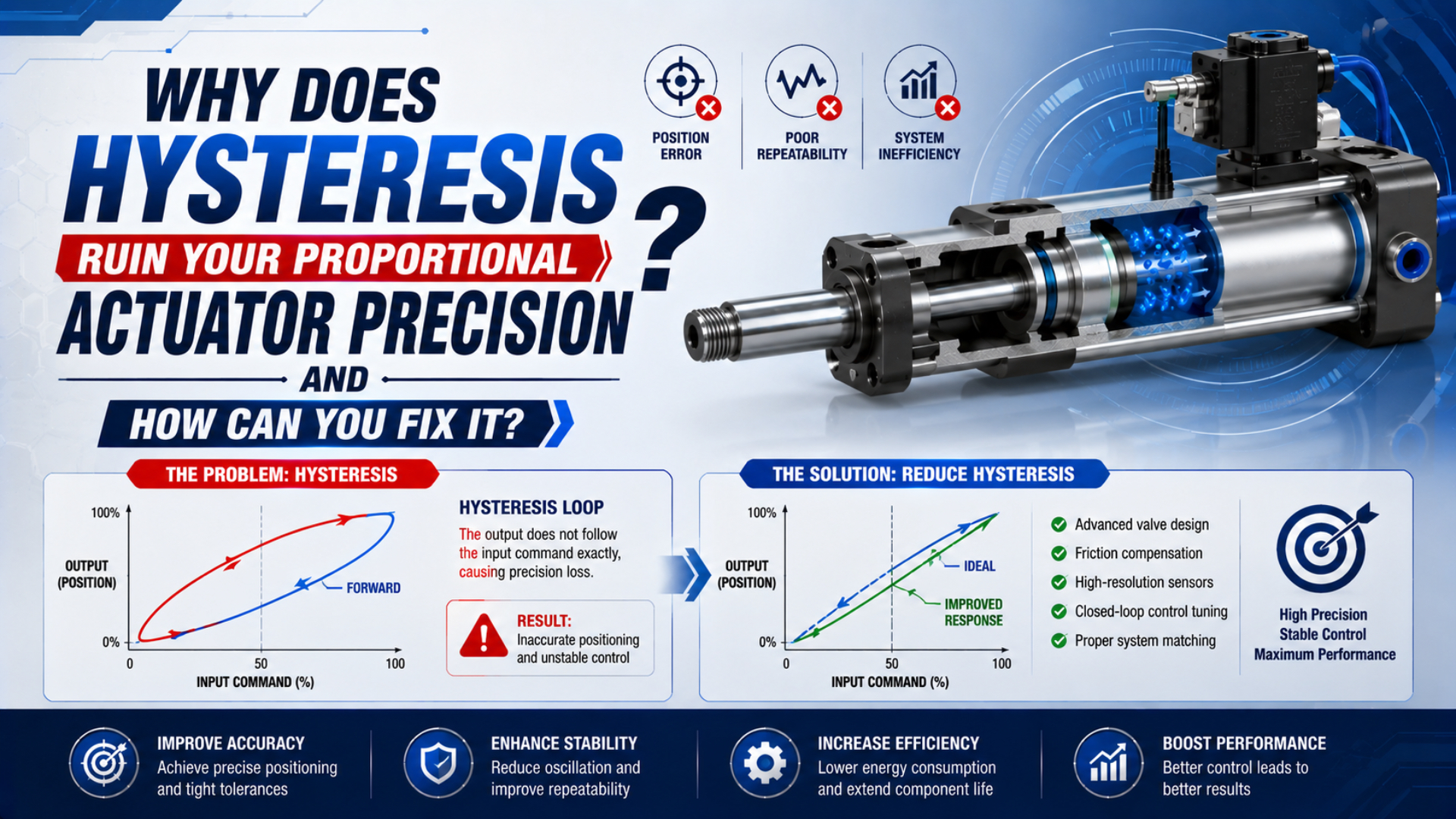
Proportional actuator hysteresis is the direction-dependent position gap that appears when an axis reaches a different position at the same command after approaching from the opposite direction. The remedy is not a universal PID setting. Measure a bidirectional command-position loop, identify where the paths separate, correct the physical cause, and compensate only the stable residual error.
A proportional pneumatic axis contains more than an actuator. Festo describes the basic system as a cylinder with displacement encoder, a proportional directional valve, and a position controller (Festo servopneumatic positioning systems, accessed 2026). Hysteresis can enter at any interface between those elements.
Direction is part of the test.
Key Takeaways
- Compare increasing and decreasing approaches at identical commands and settled conditions.
- SMC lists 0.5% FS regulator hysteresis separately from repeatability and sensitivity.
- Trace command, valve or pressure response, actuator position, and process position on one time base.
- Repair friction, play, alignment, air-path restrictions, and sensor problems before adding directional compensation.
What Does Hysteresis Mean in a Proportional Pneumatic Axis?
Bürkert defines valve hysteresis as the greatest fluidic-output difference during upward and downward traversals of the full electrical input range, normalized to maximum fluidic output (Bürkert proportional valve overview, accessed 2026). An actuator test keeps that directional idea but must name a position output.
For an installed linear axis, choose a command and a measured position . At a matched command , the absolute bidirectional gap is:
Here, is the settled position after approaching from the lower side, and is the settled position after approaching from the upper side. Report in millimeters. The command can represent demanded position, valve input, or another declared variable, but one test must not switch definitions halfway through.
The normalized result is:
Name both paths.
In this expression, is the declared measured travel, not automatically the cylinder’s catalog stroke. If the process uses only a 300 mm working window within a 500 mm cylinder, state which span forms the denominator. A percentage without that denominator cannot support a tolerance decision. Hysteresis is not the same as accuracy. Accuracy compares measured position with a reference target. Repeatability compares repeated results under a defined approach. Resolution describes the smallest represented or detectable increment. Deadband describes an input region that produces no defined response. Dynamic lag describes time-dependent tracking error. These quantities may interact, but they answer different questions.
Therefore, the most useful diagnostic name is an ordered pair: command-position hysteresis, command-pressure hysteresis, pressure-force hysteresis, or process-position hysteresis. A bare statement such as “the actuator has 1% hysteresis” hides the measurement boundary. It may describe a valve bench test, a displacement transducer, a cylinder, or the complete machine.
For component terminology and data-sheet comparisons, see the proportional-valve hysteresis and linearity guide. The pressure-control hysteresis-loop guide addresses pressure as the measured output. This article keeps final actuator or process position at the center.
Which Error Comes from the Valve, Mechanics, or Sensor?
SMC’s ITV regulator lists 0.5% FS or less hysteresis, ±0.5% FS or less repeatability, and 0.2% FS or less sensitivity as separate characteristics (SMC ITV catalog, accessed 2026). Those pressure-control figures cannot be copied directly into a carriage-position error budget.
The complete axis contains several direction-dependent effects:
| Source | Direction-dependent mechanism | Signal that reveals it | Why the position loop changes |
|---|---|---|---|
| Valve electronics or spool | Magnetic behavior, spool friction, overlap, internal control behavior | Command versus spool feedback, flow, or regulated pressure | The same electrical input produces a different pneumatic output |
| Cylinder seals | Breakaway force differs from running friction | Chamber-pressure differential rises while position remains still | More force is needed to start motion than to sustain it |
| Pneumatic path | Tube volume, restricted exhaust, supply droop, unequal port flow | Chamber pressures respond differently by direction or rate | Available acceleration and braking force depend on direction |
In contrast, the next three sources sit in the measurement, mechanics, or control path:
| Source | Direction-dependent mechanism | Signal that reveals it | Why the position loop changes |
|---|---|---|---|
| External guide or linkage | Backlash, preload, binding, misalignment, cable force | Actuator position changes before process position, or force reverses across play | Lost motion appears between the sensor datum and process datum |
| Position sensor | Sensor hysteresis, mounting movement, calibration error, filtering | External reference disagrees with onboard position | The controller corrects toward a biased measurement |
| Controller | Dead-zone logic, integral state, saturation, direction-specific mapping | Position error changes when software state is reset or compensation is disabled | The command path itself becomes history-dependent |
For example, Festo’s DFPI external-feedback actuator is a useful warning against treating every position signal as perfect. Its catalog lists ±0.12 mm repetition accuracy and 0.33 mm displacement-encoder hysteresis for the specified version (Festo DFPI data, accessed 2026). These are model-specific sensor-chain values, not universal cylinder limits. In addition, pressure dynamics deserve a separate test. Air compressibility and tube volume create delay and compliance, but delay alone is not static hysteresis. If a loop becomes wider as command rate increases and collapses after sufficient settling, the dominant problem is dynamic tracking. The air-compressibility control guide explains that rate-dependent path.
Similarly, mechanical backlash needs its own measurement. A sensor mounted on the actuator may report the commanded position while a loose coupling, guide clearance, or fixture remains on the other side of its play. Measure at the process datum whenever the product tolerance belongs there. Otherwise a tight controller trace can coexist with a poor assembly result.
How Do You Measure Direction-Dependent Position Error?
ISO 230-2:2014 uses repeated direct measurements at each position to evaluate positioning accuracy and repeatability of linear or rotary machine-tool axes (ISO 230-2, confirmed 2025). It is not a pneumatic actuator standard, but its matched-position, repeated-measurement discipline is a sound acceptance-test model.
Start by defining the test boundary:
- Name the input. Record whether is demanded position, analog valve command, regulated-pressure target, or controller output.
- Name the output. Use actuator position, carriage position, tool-center position, or process feature position. Do not substitute one for another.
- Define the working span. State endpoints, forbidden end zones, mounting orientation, payload, guide, and process contact state.
- Define the timing rule. A static test needs a declared settling band and dwell rule. A dynamic test needs a declared profile, sample rate, and filter.
- Fix operating conditions. Record supply pressure during motion, temperature, air quality, tubing, fittings, silencers, valve model, controller version, and gain set.
- Use a traceable reference. Its uncertainty and resolution must be small enough to judge the required position band.
Next, run complete rising and falling sequences through identical target points. Approach each point from the declared direction without a final corrective jog that reverses direction. Record repeated loops rather than one attractive trace. If the production cycle contains a different speed, load, or approach direction, test that condition separately.
Suppose an illustrative 500 mm working span produces 250.4 mm after an increasing approach and 249.6 mm after a decreasing approach at the same command. The absolute gap is:
The normalized gap is:
However, this calculation reports direction-dependent separation at one point. It does not prove ±0.4 mm accuracy, because the average position could still be offset from the reference. It also does not establish repeatability until the same-direction sequence is repeated and its dispersion is reported. Therefore, keep static and dynamic tests separate. First use settled points to expose persistent path dependence. Then run the production motion profile to measure following error, overshoot, settling time, and reversal behavior. Combining both into one loop makes pneumatic delay look like static hysteresis and encourages the wrong correction.
A Signal-by-Signal Diagnostic Method
Festo describes a servo-pneumatic positioning system with three core control elements: displacement encoder, proportional directional valve, and position controller (Festo, accessed 2026). Adding both chamber pressures and an external process-position reference turns those three elements into a practical fault-isolation chain.
Capture these channels on one time base:
- demanded position;
- controller position error, valve command, integral state, and output saturation;
- valve-spool feedback when available, or measured flow or pressure response if it is not;
- both chamber pressures;
- actuator displacement;
- external carriage, tool, or process position measured at the tolerance datum with an independent instrument whose uncertainty supports the acceptance decision;
- load or force when process contact changes the motion.
Specifically, the chamber-force relationship helps interpret the trace:
Here, and are measured chamber pressures, and are effective piston areas, is the external load projected onto the axis, and represents seal, guide, and mechanism friction. Use dynamic pressure at the cylinder ports where practical, not only the upstream regulator setting.
Then read the traces in order. Start with the first split:
- Command separates before the valve. Direction-specific controller bias, integrator state, saturation, or compensation is creating the difference.
- Valve or pressure separates at the same command. Investigate the valve characteristic, contamination, supply variation, exhaust restriction, and signal scaling.
- Pressure differential changes but position waits. Seal stiction, guide binding, side load, or process contact is resisting motion.
- Actuator position moves but process position waits. Backlash, coupling play, fixture compliance, or sensor placement is hiding lost motion.
- Only faster profiles widen the loop. Treat bandwidth, tube volume, flow capacity, filtering, and controller delay before static mapping.
In particular, do not add every observed percentage into a single error total. Valve pressure hysteresis, sensor position hysteresis, mechanical lost motion, and final process-position hysteresis use different outputs and denominators. Translate each contribution into the process unit only after its transfer relationship has been measured or validated.
The spool-position feedback guide explains what internal valve feedback can and cannot prove. For low-speed jerking after pressure builds, use the cylinder stick-slip diagnostic guide alongside the synchronized trace.
Why Doesn’t Feedback Automatically Eliminate Hysteresis?
Festo states that servo-pneumatic positioning uses encoder feedback and a proportional directional valve, yet the air remains compressible and the controlled axis is mechanically soft (Festo servopneumatic systems, accessed 2026). Feedback corrects measured error; it cannot directly observe every hidden friction, play, or process-datum shift.
In other words, the controller acts on:
Here, is the measured position error, is the target, and is the feedback position. If the feedback sensor is mounted before a loose coupling, the controller can reduce to nearly zero while the process tool remains displaced. The loop has no evidence of what its sensor does not measure.
For instance, friction creates another limit. Near zero velocity, the controller may increase valve command while the load remains stationary. When pressure differential finally exceeds breakaway resistance, the load jumps, the error changes sign, and the controller reverses. Raising proportional or integral gain can turn this into hunting. The symptom looks like poor tuning, but the trigger is often physical. In contrast, valve saturation removes control authority for another reason. If a small valve cannot deliver the required flow, a larger command produces no additional acceleration. If the valve is greatly oversized, small command changes may create large flow changes around the operating point. Bürkert notes that an oversized orifice can reach full flow at a small opening and impair usable resolution and control quality.
That said, feedforward can reduce predictable command demand, and integral action can remove steady bias. Neither should conceal a changing guide, leaking seal, loose joint, or unstable supply. Capture the trace before changing the loop. The PID tuning guide for proportional valve and cylinder systems provides the next step after the hardware path is stable.
What Should You Fix Before Adding Compensation?
The Festo DFPI catalog shows why one correction cannot fit every actuator: one external-feedback version lists 0.33 mm encoder hysteresis, while an integrated-controller version lists ±1% FS hysteresis and a 1% FS dead zone (Festo DFPI, accessed 2026). Fixes must match the measured subsystem and model.
Use this order. Fix what the traces reveal:
- Make the mechanism repeatable. Correct alignment, side load, loose fasteners, guide preload, coupling play, fixture deflection, cable drag, and process contact variation.
- Restore the pneumatic path. Verify air quality, dynamic supply pressure, tube inside diameter and length, fittings, silencers, valve sizing, exhaust capacity, leaks, and cylinder sealing.
- Verify the measurement chain. Confirm sensor mounting, datum, calibration, polarity, scaling, filtering, sample time, resolution, and uncertainty against an external reference.
- Confirm the valve and I/O. Check command range, electrical reference, spool or pressure response, internal diagnostics, connector integrity, contamination, and model-specific performance limits.
- Re-identify and tune the axis. Use the actual payload, orientation, supply, and motion profile. Set safe velocity, acceleration, error, and timeout limits before increasing gain.
- Map only the remaining stable error. Directional compensation is justified only when the residual pattern repeats across enough cycles and operating conditions.
Why this order? For example, a software table can cancel a stable 0.4 mm directional offset at one temperature and load. It cannot reliably cancel a coupling that moves unpredictably, seal friction that changes after maintenance, or pressure droop that appears when another machine cycles. Those faults change the map itself.
Similarly, do not use dither by default. A small high-frequency command can reduce some spool or friction effects, but it may also create audible noise, extra air use, heat, wear, pressure ripple, and unwanted motion. Use only a valve- or controller-supported method with a defined amplitude, frequency, process limit, and validation test.
Importantly, safety limits stay independent of precision tuning. Define the response to sensor loss, valve-command loss, supply loss, excessive following error, unexpected movement, and end-stop approach. Stored pneumatic energy can move the axis after electrical control changes state. Apply the machine risk assessment and relevant safety architecture before full-range testing.
Directional Mapping and Control Compensation
Festo’s 2025 MPYE data lists 0.4% maximum hysteresis relative to maximum spool travel and a 70 to 115 Hz limit frequency depending on valve size (Festo MPYE data, accessed 2026). Those figures describe one position-controlled spool family, so axis compensation must remain model- and system-specific.
After physical faults are corrected, a directional map can, for example, offset a stable residual:
Here, is the corrected command, is the original command, and is a measured correction indexed by position , direction or velocity , and load state when necessary. Keep the smallest number of dimensions that still reproduces the error.
Therefore, build the map from independent characterization data, then validate it with separate cycles. If the same data both creates and proves the map, the result can fit noise rather than the axis. Check interpolation between calibration points and behavior at the ends of the working range. Clamp corrections so a corrupted table cannot demand unsafe motion.
Alternatively, other compensation options solve different problems:
| Method | Suitable residual | Main limitation |
|---|---|---|
| Direction-specific offset | Stable position gap after reversal | Does not address rate-dependent lag |
| Friction feedforward | Repeatable force needed to initiate or sustain motion | Changes with seals, lubrication, load, and temperature |
| Valve inverse map | Repeatable command-to-flow or command-to-pressure nonlinearity | Needs matched valve conditions and usable control authority |
| Gain scheduling | Plant dynamics change predictably with position or load | Switching or interpolation must remain stable |
| Disturbance observer or state estimator | Unmeasured load changes with a validated model | Model and sensor errors can be interpreted as disturbance |
| Integral control | Steady measured bias inside available authority | Can wind up during stiction or saturation |
In addition, a correction table is best treated as a calibrated measurement asset, not casual tuning. Give it a version, axis serial or configuration identity, test conditions, creation date, approved range, checksum, and rollback path. Revalidate it after valve replacement, seal service, sensor adjustment, guide work, controller changes, or tubing changes.
How Should You Define an Acceptance Test?
ISO 230-2:2014 supports type, acceptance, comparison, periodic-verification, and compensation testing through repeated measurements at defined positions (ISO 230-2, confirmed 2025). A pneumatic-axis requirement should likewise specify positions, directions, repetitions, operating conditions, uncertainty, and the process datum instead of declaring a universal acceptable percentage.
Specifically, write separate limits for:
- bidirectional gap;
- same-direction repeatability over declared repeats and both approaches;
- absolute process-position error;
- following error during the full profile, including acceleration and reversal regions;
- overshoot and settling time;
- holding band, drift, and low-velocity hunting during dwell;
- minimum controllable movement after reversal;
- all applicable limits under minimum and maximum payload, supply, and temperature conditions, plus the required response to sensor, power, or air loss.
For example, a useful requirement reads like a test instruction: “At the listed targets, with the declared payload and supply range, approach each target from both directions using the production profile. After the stated settling rule, the process-datum position shall remain inside the specified band for the required repeats.” Add measurement uncertainty and data-retention rules.
In contrast, avoid assigning one universal “acceptable hysteresis” level to all applications. Festo’s integrated DFPI example specifies 1% FS positioning accuracy, ±1% FS hysteresis, and 1% FS dead zone for that product configuration. SMC’s ITV figure of 0.5% FS refers to regulated pressure. Neither value automatically defines a precision assembly axis. As a result, set the machine limit from the process tolerance and allocate a realistic share to measurement, control, mechanics, tooling, product variation, and environment. Keep unlike units visible until their transfer to process position is established. If the tool must stay within millimeters, finish the budget in millimeters.
Finally, preserve the raw traces. A single pass/fail number cannot show whether degradation began in valve command, pressure response, breakaway force, actuator feedback, or process mechanics. Consequently, periodic comparison of the same synchronized channels turns hysteresis testing into a maintenance diagnostic rather than a one-time commissioning exercise.
Proportional Actuator Hysteresis FAQs
SMC specifies ITV hysteresis at 0.5% FS or less while separately listing ±0.5% FS repeatability and 0.2% FS sensitivity (SMC ITV, accessed 2026). These five questions preserve those distinctions when diagnosing a complete proportional pneumatic positioning axis during commissioning work.
Is hysteresis the same as poor repeatability?
No. Hysteresis compares outputs at the same input after approaching from opposite directions. Repeatability compares repeated outputs under the same defined approach. An axis may repeat tightly on each directional path while the two paths remain separated. Report bidirectional gap and same-direction dispersion as separate quantities with their own units and conditions.
Does closed-loop position control eliminate actuator hysteresis?
No. Feedback corrects error visible at its sensor, but it cannot directly observe coupling play, fixture movement, process compliance, or a biased sensor. It also needs enough valve authority to overcome friction without hunting. Closed-loop control can reduce stable error, yet the complete loaded axis still requires bidirectional acceptance testing.
Can higher PID gain fix direction-dependent positioning error?
Sometimes it reduces a small measured bias, but gain cannot remove backlash, binding, valve saturation, or a moving sensor datum. Integral action may wind up during stiction and release as overshoot. Correct the physical and pneumatic path first, then tune from synchronized command, pressure, position, and error traces.
How much sensor resolution is needed for a hysteresis test?
Use a measurement system whose resolution, repeatability, calibration uncertainty, mounting stability, and sample behavior can support the required decision. Bit count alone is insufficient. Compare the onboard sensor with an external reference at the process datum, and apply a documented guard band when measurement uncertainty is significant relative to the acceptance limit.
What is an acceptable proportional actuator hysteresis limit?
There is no universal percentage. Define the limit from process-position tolerance, payload, approach direction, working span, supply range, temperature, motion profile, settling rule, repetitions, and measurement uncertainty. Manufacturer values apply to the named component and test boundary; approve the complete axis only against its own process-datum acceptance test.
Sources and technical references
- Bürkert, Product Overview: Proportional Valves. Hysteresis and repeatability definitions; retrieved 2026-07-23.
- SMC, ITV Series Electro-Pneumatic Regulator Catalog. Model-specific pressure-control characteristics; retrieved 2026-07-23.
- Festo, Servopneumatic Positioning Systems. System architecture; retrieved 2026-07-23.
- Festo, DFPI Linear Actuator Technical Data. Sensor-chain and integrated-controller examples with different units and boundaries; retrieved 2026-07-23.
- Festo, MPYE Proportional Directional Control Valve. Model-specific spool hysteresis and frequency data; published 2025-03 and retrieved 2026-07-23.
- ISO 230-2:2014, Accuracy and Repeatability of Positioning of Numerically Controlled Axes. Repeated-position measurement discipline for acceptance and periodic verification, not a pneumatic component specification; confirmed 2025 and retrieved 2026-07-23.