

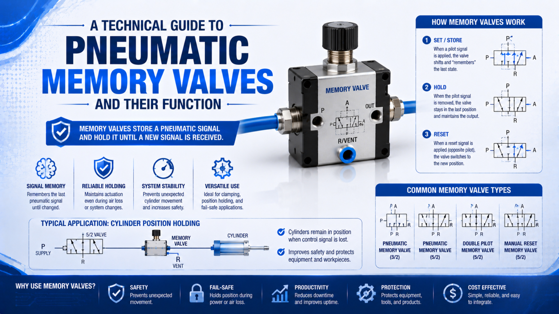
A pneumatic memory valve is a bistable control element that keeps its last commanded spool state after the set or reset signal disappears. Festo describes command memory modules as double-pilot valves and uses them in pneumatic step sequences (Festo, Control Technology, accessed 2026). The valve remembers a control state. It does not measure or guarantee cylinder position.
That distinction prevents a common design error. A valve can retain its routing state while supply pressure falls, downstream air leaks away, or an external load moves the actuator. Electrical power loss, pilot-signal loss, and main-air loss are separate events, so each needs its own machine response.
Key Takeaways
- A memory valve stores a spool or command state, not measured actuator position.
- A 5/2 bistable valve needs a separate opposing signal to change state.
- Retained routing does not guarantee retained pressure or load holding.
- Safety functions require system-level design and validation.
For the broader control context, compare this guide with pneumatic logic valve functions. This article stays narrower: it explains the memory element itself, its loss behavior, and the checks needed before putting one into a machine circuit.
What Does a Pneumatic Memory Valve Actually Remember?
Festo identifies the command memory modules in a pneumatic stepper chain as double-pilot valves, with one module assigned to each sequence stage (Festo, Control Technology, accessed 2026). The retained information is the valve’s last switching state, not a digital record, pressure measurement, or confirmed actuator location.
A bistable directional valve has two stable routing states. A brief signal at one pilot or solenoid shifts the spool to state A. The signal can then disappear. A separate signal at the opposing pilot or solenoid shifts the spool to state B. This set-reset behavior is why technicians often call the component a memory valve, impulse valve, double-pilot valve, or bistable valve.
The names are related, but they are not interchangeable in every catalog. “Memory valve” may refer to a dedicated pneumatic logic module, a mechanically detented directional valve, or a double-pilot spool valve used as the state element in a sequence. Always read the symbol and actuation description before assuming how a part behaves.
| Layer | What may be retained | What is not proven |
|---|---|---|
| Control signal | the last set or reset command | that the spool completed its movement |
| Valve state | the selected internal flow path | that downstream pressure remains available |
| Actuator state | nothing unless feedback confirms it | exact position, clamp force, or safe load holding |
Treat memory as a command-layer property. If the machine needs physical position memory, use position sensing and a controller state that can be reconciled during restart. If the machine needs load holding, use a device and architecture designed for that hazard, such as a suitable rod lock, brake, pilot-operated check arrangement, or mechanical restraint.
How Does a Bistable Memory Valve Switch Internally?
Festo distinguishes a monostable valve with one actuation from a bistable valve with two actuations. The monostable valve returns when its signal disappears, while the bistable valve requires a separate return signal (Festo, Pneumatic Valves, accessed 2026). That two-command architecture creates the practical memory function.
In a pneumatic double-pilot design, pressure at pilot port 14 shifts the main spool toward one flow state. After the spool crosses its switching point, the internal geometry and pilot arrangement keep that state when the pilot pulse vents. Pressure at pilot port 12 then shifts it back. Port numbers and signal sides must be confirmed from the actual symbol because manufacturers can orient drawings differently.
An electrically operated version uses two solenoids instead of two air pilots. Energizing one coil selects one state; energizing the other selects the opposite state. Two coils alone do not prove bistability. Festo notes that a 5/3 valve can have two solenoids yet still return to a spring-centered middle position when de-energized (Festo, Pneumatic Valves, accessed 2026).
Set and reset sequence
| Step | Input condition | Expected valve result | Required evidence |
|---|---|---|---|
| 1 | set signal reaches the specified pilot or coil | spool changes to state A | outlet pressure or spool feedback changes as expected |
| 2 | set signal is removed | bistable spool remains in state A | state remains stable for the specified test period |
| 3 | reset signal reaches the opposite pilot or coil | spool changes to state B | opposite outlet and exhaust paths are verified |
| 4 | reset signal is removed | bistable spool remains in state B | restart logic agrees with the physical machine state |
The set and reset signals should not overlap unless the manufacturer explicitly defines the outcome. With two pneumatic pilots active at once, pressure balance, pilot area, internal friction, or arrival order may determine which state wins. A circuit that works during slow manual testing can therefore become unpredictable at production speed.
Why Doesn’t Valve Memory Guarantee Cylinder Position?
A 5/2 memory valve has five ports and two spool positions, but those two positions describe air routing rather than cylinder location. ISO 4414 covers significant hazards across pneumatic-system design and operation, so pressure decay, external load, leakage, exhaust paths, and restart behavior must be assessed as system properties (ISO 4414, 2010).
Consider a double-acting cylinder stopped at full extension. The memory valve may still route supply air to the cap end after its pilot pulse disappears. If the main air supply remains healthy, the cylinder can stay commanded outward. That is not the same as knowing the piston reached the end of stroke, maintaining a specified clamp force, or preventing motion after the supply is isolated.
If main air disappears, both cylinder chambers can lose pressure through leakage, seals, valves, fittings, or connected exhaust paths. Gravity or an external process force may then move the load. Restoring air can also produce unexpected motion because the retained spool state immediately reconnects supply to one working port.
This boundary is especially important for a vertical actuator. A bistable directional valve can preserve the last command while the load still drifts or falls after pressure loss. Review the separate article on safety exhaust valve integration when the circuit includes guarded machinery or stored-energy hazards.
A useful restart rule is “observe before command.” After air or electrical power returns, compare sensors, pressure switches, valve feedback where available, and the controller’s stored state. Do not let a stale pneumatic or PLC memory state launch motion merely because supply pressure has returned.
Which Valve Configurations Can Provide Memory?
SMC’s current SY working-principle material separates 5-port valves into 2-position single, 2-position double, and three different 3-position center arrangements (SMC, SY Working Principle, accessed 2026). Only the actuation and return mechanism, not the number of coils by itself, determines whether a valve retains its selected state.
| Configuration | State after command removal | Typical use | Main caution |
|---|---|---|---|
| 3/2 double-pilot or detented | retains one of two port states | set-reset signal, small pilot circuit | confirm exhaust behavior and reset signal |
| 5/2 double-pilot | retains extend or retract routing | double-acting cylinder direction | does not create a neutral or blocked center |
| 5/2 double-solenoid bistable | retains the selected routing state as designed | electrically commanded direction | check power restoration and simultaneous-coil rules |
| mechanically detented manual valve | physically stays in selected position | local operator command | manual state may conflict with automatic control |
| spring-return monostable valve | returns to its normal state | defined default routing | not a last-state memory valve |
| spring-centered 5/3 valve | returns to its center condition | stop, exhaust, pressure, or blocked-center functions | center behavior is not last-state memory |
Festo’s teaching product for this function is a directly operated, bistable 5/2 piston-spool valve actuated pneumatically on both sides (Festo, 5/2-Way Double Solenoid Valve, accessed 2026). That is a concrete construction example, not a universal specification for all memory valves.
When reading a symbol, identify the number of ports, number of positions, operator on each side, spring symbols, pilot ports, exhaust ports, and normal or retained state. Our guide to 5-port directional valve operation explains the port-routing layer in more detail.
How Should Memory Valves Be Used in Control Circuits?
Festo assigns one command memory module to each cycle stage in its pneumatic stepper-chain description (Festo, Control Technology, accessed 2026). The same ownership principle applies to modern machines: one layer should own the commanded state, while sensors verify the machine result and separate safety functions supervise hazards.
Set-reset pneumatic logic
A simple air-only memory circuit uses one pilot as SET and the opposite pilot as RESET. Manual 3/2 valves, limit valves, pressure signals, or other logic elements can create those pulses. The circuit must vent each completed pilot signal cleanly. Trapped pressure can prevent reset, create opposing commands, or make the result depend on pressure balance.
Sequence control
In a step sequence, the memory element holds the active command until qualified completion evidence advances the circuit. A timer can supervise maximum travel time, but it should not automatically replace end-position feedback. The worked method in sequential pneumatic circuit design shows how to separate permission, completion evidence, timeout, and fault response.
PLC and valve ownership
A PLC can remember a sequence step, and a bistable valve can remember a spool state. Letting both independently own the same motion creates two authorities. After a restart, the PLC may restore one step while the valve still routes air for another. Assign one state owner, define the other as an interface, and specify how disagreement is detected and resolved.
The best reason to use pneumatic memory is not merely “it works without continuous electricity.” It is that local state retention can simplify a justified air-only sequence or preserve a command through a brief control-signal gap. If the machine already has reliable PLC state, feedback, diagnostics, and restart logic, an additional pneumatic latch may add ambiguity rather than resilience.
For larger valve manifolds, use the architecture checks in modular pneumatic circuit design. They help document supply zones, exhaust paths, interfaces, and fault behavior before component selection.
Memory Valve Selection Data
Festo’s example 5/2 bistable teaching valve uses pneumatic actuation on both sides and a 4 mm push-in connection, illustrating why configuration and interface details are model-specific (Festo, 5/2-Way Double Solenoid Valve, accessed 2026). Never transfer one product’s pilot pressure, connection, temperature, flow, or leakage limits to another family.
Use this selection checklist:
| Datasheet field | Why it matters | What to record in the RFQ or design file |
|---|---|---|
| valve function and symbol | proves whether the valve is truly bistable | 3/2 or 5/2, actuation on both sides, port map |
| main pressure range | defines the permitted working supply | minimum, normal, and maximum point-of-use pressure |
| pilot pressure range | determines whether set and reset pulses will switch reliably | worst-case pilot pressure during peak machine demand |
| internal or external pilot | changes low-pressure and vacuum behavior | pilot source, regulator, and loss response |
| flow capacity | affects downstream response and actuator speed | manufacturer flow data under stated test conditions |
| response and minimum pulse | determines whether short commands are accepted | actual signal duration and tubing delay |
| leakage specification | affects retained pressure, not just air cost | allowable decay and test duration |
| media and filtration | protects pilots, seals, and spool clearances | air quality, lubrication policy, contamination risk |
| temperature and seal material | limits environmental suitability | ambient, media, washdown, and chemical exposure |
| manual override and indication | affects commissioning and unexpected operation | locking behavior, access control, feedback method |
| mounting and orientation | can affect tubing, drainage, and service access | manifold or body mounting, exhaust routing |
Valve flow still matters when the memory element directly controls an actuator. Use the Cv sizing guide to understand the inputs, then confirm the chosen part against its manufacturer flow curves and operating conditions. A calculator link is intentionally not used as the main workflow here because memory behavior, not flow calculation, is the primary selection question.
Commissioning and Troubleshooting a Memory Function
ISO 4414:2010 was confirmed in 2021 and covers pneumatic-system design, installation, adjustment, operation, maintenance, reliability, and significant hazards (ISO 4414, 2010). Commissioning should therefore test the complete state transition and loss response, not merely prove that the spool changes during one bench pulse.
- Confirm the symbol and port numbers. Trace supply, working, exhaust, set, and reset connections against the manufacturer drawing.
- Measure pilot pressure at the valve. A gauge near the regulator may hide pressure loss in a long or restricted pilot line.
- Test SET and RESET independently. Apply the specified pulse, remove it, and confirm that the spool state remains until the opposing command arrives.
- Test signal overlap. Verify the specified outcome when pulses overlap or arrive in the wrong order. If the datasheet does not define it, prevent overlap in the control design.
- Check downstream pressure separately. Record pressure decay over a justified interval. Do not infer pressure retention from spool retention.
- Interrupt electrical power, pilot air, and main air separately. Observe the valve, actuator, load, feedback, and controller response for each event.
- Restore supplies under controlled conditions. Confirm that retained commands cannot cause an unexpected restart.
- Repeat at worst operating conditions. Include minimum permitted pressure, peak simultaneous air demand, realistic tube lengths, contamination controls, and the actual load.
| Symptom | Measure first | Likely causes |
|---|---|---|
| valve will not set | pilot pressure at the set port | weak signal, blocked pilot, incorrect porting, spool contamination |
| valve sets but will not reset | both pilot ports and exhaust paths | trapped set pressure, blocked exhaust, overlapping commands |
| state changes during vibration | actual valve construction and mounting | wrong monostable part, inadequate detent, mechanical damage |
| cylinder drifts after air loss | both chamber pressures and load force | leakage, open exhaust path, no mechanical holding device |
| machine moves when air returns | retained spool state and restart logic | stale command, missing position reconciliation, automatic repressurization |
| cycle fails only at production speed | pilot pulse width and pressure trace | short pulse, tube-volume delay, shared supply pressure drop |
Do not dismantle or modify a memory valve unless its manufacturer provides a service procedure. If contamination or internal wear is suspected, correct the air-quality cause, replace the component where appropriate, and repeat a documented acceptance test. The general solenoid valve operating guide provides additional electrical and pilot-stage context.
In our experience, the fastest useful diagnostic is to measure both pilot ports before replacing the valve. A reset complaint is often caused by pressure trapped on the opposite pilot, a blocked exhaust, or a pulse that disappears before it reaches the valve. That check separates circuit faults from internal valve faults.
Pneumatic Memory Valve FAQs
Two standards define the safety boundary around this component: ISO 4414 addresses pneumatic-system hazards, while ISO 13849-1:2023 applies to safety-related control systems using pneumatic and other technologies (ISO 4414, 2010; ISO 13849-1, 2023). Neither turns an ordinary memory valve into a complete safety function.
Does a pneumatic memory valve hold cylinder position after air loss?
No. It may retain the spool’s selected flow path, but chamber pressure can decay through leakage or exhaust paths. Gravity and external forces can then move the actuator. Use feedback to verify position and a risk-assessed mechanical or pneumatic holding method when uncontrolled movement could create a hazard.
Is a double-solenoid valve always a memory valve?
No. A 2-position double-solenoid valve may be bistable, but a spring-centered 5/3 valve can also have two coils and still return to its center position when de-energized. Confirm the symbol, operator and spring arrangement, and manufacturer’s description rather than counting coils.
What is the difference between a memory valve and a shuttle valve?
A memory valve retains one of two commanded states until an opposing signal changes it. A shuttle valve performs pneumatic OR logic by selecting either available inlet and isolating the other. The shuttle does not store the last input after both signals disappear, so it is not a substitute for a set-reset element.
Can a memory valve be used in a safety-related control system?
It can be one assessed component, but its bistable behavior alone does not establish a safety function or required performance level. ISO 13849-1:2023 covers pneumatic safety-related controls but does not prescribe the function or PLr for a specific machine. Architecture, diagnostics, fault response, reset, and validation still matter.
How should a pneumatic memory valve be reset after maintenance?
Follow a documented restart procedure. First verify actuator position, load condition, guards, pressure state, and controller state. Then apply the intended reset signal under controlled conditions and confirm the resulting flow path before enabling automatic motion. Never assume that venting or restoring air erased the retained spool state.
Sources and technical references
- Festo, Control Technology and Remote I/O. Command memory modules and double-pilot stepper-chain description. Retrieved 2026-07-22.
- Festo, Pneumatic Valves. Monostable and bistable operating distinctions. Retrieved 2026-07-22.
- Festo, 5/2-Way Double Solenoid Valve, Pneumatically Operated on Both Sides. Product construction example. Retrieved 2026-07-22.
- SMC, SY3000/5000/7000/9000 5-Port Solenoid Valve Working Principle. Single, double, and center-position configuration reference. Retrieved 2026-07-22.
- ISO 4414:2010. Pneumatic fluid power general rules and safety requirements. Retrieved 2026-07-22.
- ISO 13849-1:2023. Safety-related parts of control systems, including pneumatic technology. Retrieved 2026-07-22.