

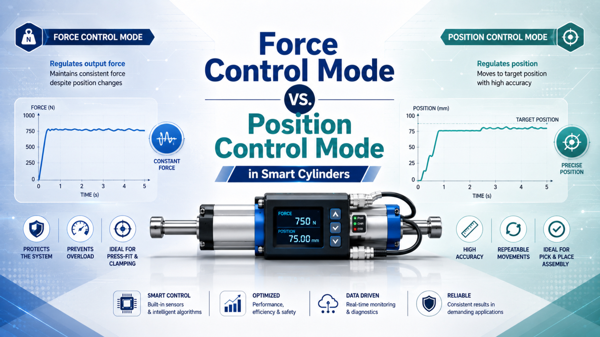
Choose position control when the machine must reach and hold a measured location. Choose force control when the process must build and regulate load against a workpiece. If both matter, use a supervised sequence: approach under position control, confirm contact, regulate force, then retract under position control.
At the system level, comparing force control mode vs position control mode in smart cylinders is really a choice about which measurement closes the loop. Chamber pressure can support a force estimate; it doesn’t directly measure workpiece force. Likewise, a position encoder can close a motion loop, but it can’t guarantee a safe contact load. Here, a smart cylinder means a servo-pneumatic axis with continuous feedback, a proportional directional valve, and an axis controller, not a standard cylinder fitted only with end switches.
Key Takeaways
- Festo defines a servo-pneumatic positioning system with 3 core elements: an encoded cylinder, proportional directional valve, and position controller.
- Pressure-derived force uncertainty includes unmodeled friction and downstream load-path effects.
- Use position mode for travel, direct force feedback for critical contact load, and supervised switching when one cycle needs both.
What Separates Force Control from Position Control?
Festo describes a servo-pneumatic positioning system as 3 connected elements: a cylinder with displacement encoder, a proportional directional valve, and a position controller. The same system can target a position or generate a target force, but the chosen feedback variable and acceptance test remain different (Festo servo-pneumatic positioning systems, retrieved 2026).
Position control minimizes position error:
The variable is position error, is the commanded position, and is the position reported by the encoder. All three use the same distance unit. The controller meters air into and out of the cylinder chambers until the measured position satisfies the defined in-position criteria.
Force control minimizes force error:
In this equation, is force error, is the requested force, and is either a pressure-derived estimate or a direct force-sensor measurement. Those two feedback choices are not interchangeable. The controller can report a stable estimated force while the actual load at the tool changes because of guide friction, fixture flex, or contact geometry.
| Engineering question | Position control | Pressure-derived force control | Direct force control |
|---|---|---|---|
| Controlled variable | Measured axis position | Calculated piston force | Measured load in the force path |
| Primary sensors | Continuous displacement encoder | Pressure sensors for both chambers, plus position feedback for supervision | Load cell or force transducer, usually with position feedback |
| Best use | Travel, indexing, multi-position handling | Controlled pneumatic effort where friction uncertainty is acceptable | Pressing, testing, or assembly with a contractual workpiece-force limit |
| Main blind spot | Contact force | Friction and load-path effects | Position after compliance or part deformation |
For the sensing options behind the position loop, see the guide to pneumatic cylinder position sensing technologies. Valve behavior and axis accuracy are also separated in the proportional-valve position-control guide.
What Does Each Feedback Device Actually Measure?
Festo’s CPX-CMAX manual makes a decisive distinction: its force mode controls pressure forces in 2 cylinder chambers, and says direct workpiece-force control would require a force sensor. It also states that friction in the cylinder and guide is not included in the calculated force (Festo CPX-CMAX control manual, retrieved 2026).
A useful control drawing must show the physical measurement point. If the sensor sits in a cylinder port, it measures pressure at that port. If it sits on the carriage, it measures carriage position. If a load cell sits between the actuator and the tool, it measures the load transmitted through that particular mechanical path.
This distinction also prevents a common specification error. A proportional pressure regulator can have published linearity and hysteresis figures, yet those values describe regulated pressure at its sensor. ISO 10094-1:2021 requires suppliers to publish defined characteristics for electro-pneumatic continuous pressure-control valves; it does not convert a regulator specification into cylinder-axis force accuracy (ISO 10094-1:2021).
Pressure-Based Force Is Only an Estimate
Pressure-derived force remains an estimate even after both chamber pressures are measured. The Festo CPX-CMAX algorithm also uses piston and rod diameters, mounting position, base load, and payload, yet its manual says uncertainty remains in the range of the drive’s static friction because cylinder and guide friction aren’t modeled (Festo CPX-CMAX control manual, retrieved 2026).
For extension of a double-acting, single-rod cylinder, start with the two effective areas:
The full piston area is , the annular rod-side area is , the piston diameter is , and the rod diameter is . Use metres and pascals for a result in newtons, or apply a consistent engineering-unit conversion.
For a horizontal axis moving slowly in the extension direction, the quasi-static estimate is:
The terms and are cap-end and rod-end chamber gauge pressure. The term opposes incipient extension, but it isn’t one fixed known value. Near rest or reversal, treat friction as a direction-dependent uncertainty band.
For a dynamic axis inclined by angle above horizontal, with extension defined as positive, use the signed force balance:
The total moving mass is , acceleration along the positive extension axis is , and gravitational acceleration is . The angle is positive when the axis rises above horizontal. The term is the nonnegative friction-force magnitude opposing positive extension. For retraction, rewrite the balance with the pressure-area roles and friction direction reversed. Exhaust restriction can therefore reduce usable force even when supply pressure looks stable.
Consider a horizontal 50 mm bore cylinder with a 20 mm rod during quasi-static extension. At 5.0 bar in the cap chamber and 0.8 bar in the rod chamber, the ideal two-pressure estimate before friction is about 850 N. The shortcut gives about 982 N. Ignoring rod-side pressure overstates this case by roughly 132 N, or 15.5%. That calculation is a sizing baseline, not a closed-loop accuracy claim. Measure both chamber pressures during the actual event, check exhaust backpressure, and use a load cell if the process acceptance criterion is force at the tool. The pressure-differential force guide and backpressure guide cover those two terms in more detail.
Position Control Mode Selection Criteria
Position control fits programmable travel, indexing, and measured-location tasks. Festo lists 128 configurable position sets for the CPX-CMAX and allows up to 8 modules to operate independently, but those model-specific figures don’t establish universal axis accuracy (Festo CPX-CMAX product documentation, retrieved 2026).
Choose position control when the accepted result is a measured location, path, or motion profile. Typical examples include changing format positions, aligning a carriage with several stations, tracking a commanded trajectory, and returning a tool to a verified safe location. Continuous position feedback is essential. A reed switch can confirm an endpoint, but it can’t support a continuously corrected mid-stroke position loop. Don’t specify “accuracy” as one isolated number. Define the measured datum and test at the finished tool, not only at the cylinder carriage. Record commanded position, measured position, approach direction, payload, speed, supply pressure, tube length, temperature, and dwell time. Then separate these terms:
- Resolution is the smallest reported increment.
- Repeatability is the spread when the same move is repeated under defined conditions.
- Accuracy compares the measured result with a traceable reference.
- In-position stability describes movement while the axis is commanded to remain still.
- Settling time measures how long the axis takes to enter and remain inside the acceptance band.
What happens when the tool contacts an obstruction before reaching its position? The position error remains, so the controller may continue commanding valve output. A production position loop therefore needs force, pressure, output, velocity, and timeout limits. Position control is not a substitute for contact safety.
Force Control Mode Selection Criteria
Force mode belongs in a supervised contact process, not in uncontrolled travel until pressure rises. The CPX-CMAX manual treats force setpoint, force tolerance, force ramp, software end positions, speed monitoring, and stroke monitoring as separate parameters, confirming that load regulation and motion supervision must work together (Festo CPX-CMAX control manual, retrieved 2026).
Choose force control when part height or compliance varies and process quality depends on contact load. Press fitting, clamping, surface following, tensioning, and force-displacement testing can fit this pattern. First decide whether pressure-derived force is adequate. If friction, tooling flex, or product damage makes the allowable error narrow, measure force directly in the load path. Force control still needs position supervision. If the expected workpiece is missing, an actuator seeking force may continue moving because no counterforce develops. The Festo manual warns that this condition can produce high speed and an unbraked end-of-stroke event, which is why its force mode provides critical-speed and critical-stroke monitoring.
Use a force ramp instead of an abrupt step when contact shock matters. Also define maximum travel after contact detection, maximum pressure in each chamber, maximum valve command, dwell time, and the response to a broken sensor. The control loop doesn’t replace a mechanical load rating, an independent safety function, or a risk assessment. Pressure regulation can still be useful inside the architecture. It can set a repeatable pressure command or limit available effort. Yet a proportional pressure regulator and proportional flow valve control different variables, and neither one alone guarantees workpiece force.
How Should Position and Force Modes Be Sequenced?
A reliable position-to-force sequence minimizes uncontrolled travel before force regulation begins. For its fastest controlled force build-up, the Festo CPX-CMAX manual recommends positioning the drive less than 1 mm from the press position. That is a model-specific method, not a universal transition distance (Festo CPX-CMAX control manual, retrieved 2026).
Use a state machine, not a timer-only mode change. A timer can expire even when the part is missing, the axis is late, or the pressure signal has drifted. Each transition should require measured conditions and should have an independent timeout.
| State | Required entry evidence | Data to record | Fault example |
|---|---|---|---|
| Approach | Axis referenced; command inside safe range | Command, position, velocity | Following error or timeout |
| Contact search | Inside validated approach window | Position, both pressures, force signal | Travel limit reached without contact |
| Force ramp | Contact confirmed and sensors plausible | Force setpoint, feedback, ramp, valve output | Force overshoot or no force rise |
| Dwell | Force inside acceptance band | Mean, peak, minimum, duration, position drift | Force leaves band |
| Release and retract | Force below release threshold | Residual force, retract trace, final position | Load remains trapped |
Mode switching should not be specified as a universal number of milliseconds. The physical transition depends on controller logic, valve dynamics, tubing volume, chamber volume, contact stiffness, payload, and the force ramp. Approve the complete measured sequence instead.
Safety Limits and Acceptance Tests
ISO 4414:2010 is a 38-page international standard covering significant pneumatic-system hazards across design, installation, adjustment, operation, and maintenance. A normal position or force loop is therefore only one layer; the machine still needs a defined safe state and risk-based protective measures (ISO 4414:2010).
Start by defining what happens on loss of electrical power, loss of air supply, encoder failure, pressure-sensor disagreement, load-cell overload, broken tubing, valve communication loss, and an emergency stop. A vertical load may require a mechanically rated brake or locking device. Exhausting a circuit can also release stored energy or drop a suspended mass, so “dump the air” isn’t a universal safe response. Commissioning should produce traces, not impressions. Record command position, measured position, cap pressure, rod pressure, direct force if fitted, valve command, controller state, limit flags, and timestamps. Test at minimum and maximum payload, low and high supply pressure, both approach directions, relevant temperature limits, and representative tube lengths.
Use separate acceptance criteria for each mode:
| Position-mode metric | Force-mode metric | Sequence and safety metric |
|---|---|---|
| Accuracy at the defined datum | Force accuracy at the defined load cell | Maximum travel after contact detection |
| Repeatability by approach direction | Repeatability over part and temperature range | Maximum force or pressure overshoot |
| Overshoot and settling time | Force ramp and dwell stability | Transition timeout and fault response |
| In-position drift | Position drift during force dwell | Safe response to missing workpiece |
| Following error over the motion profile | Difference between estimated and directly measured force | Restart behavior after interrupted cycle |
One component data sheet can’t approve this table. For example, the CPX-CMAX literature lists VPWP proportional valves at 350, 700, 1,400, and 2,000 L/min. Those four nominal flow classes help with component selection, but the finished axis response still depends on its complete pneumatic volume, restrictions, load, and tuning.
Which Control Mode Fits Your Application?
The CPX-CMAX maps direct-mode control bit B1 to 0 for position and 1 for force, yet its manual still defines different limits, ramps, and monitoring behavior for each state. One software bit can select a mode; it cannot make the two control objectives equivalent (Festo CPX-CMAX control manual, retrieved 2026). Use the process acceptance criterion to make the decision:
| Primary requirement | Recommended architecture | Essential acceptance test |
|---|---|---|
| Reach several programmed locations | Position control with continuous encoder | Position error, repeatability, settling, and fault response under load |
| Apply approximate pneumatic effort | Dual-pressure force estimation with supervised position | Compare calculated force with a reference load cell over the operating range |
| Protect a delicate or regulated assembly | Direct load-cell force control with position supervision | Force overshoot, dwell stability, travel limit, and sensor-fault response |
| Move quickly, then press | Staged position approach, guarded contact, force ramp, and position retract | Complete time-synchronized position, pressure, force, and state trace |
| Hold a suspended load | Risk-assessed motion control plus a suitable mechanical holding measure | Power-loss, air-loss, brake, restart, and trapped-energy tests |
If the RFQ says only “smart cylinder with force and position control,” it is incomplete. Add the controlled variable, sensor type and location, force-estimation method, payload, orientation, stroke, speed profile, tubing, pressure range, allowable error, safe state, and acceptance procedure. That information determines whether the project needs a pressure-based estimate, direct force feedback, or a different actuator technology.
FAQs About Smart Cylinder Control Modes
The CPX-CMAX offers 2 selectable direct control modes, position and force, but its internal force feedback remains pressure-derived. Direct workpiece-force control requires a controller or supervisory outer-loop architecture that accepts an external load-cell signal. These FAQs keep that product example separate from universal requirements (Festo CPX-CMAX control manual, retrieved 2026).
Can pressure sensors replace a load cell for force control?
Pressure sensors can estimate piston force when both chamber pressures, effective areas, payload, orientation, and friction allowance are known. They don’t directly measure tool force. If process acceptance depends on actual workpiece load, install a calibrated force sensor in the relevant load path and verify its alignment, range, overload capacity, and measurement uncertainty.
Can one controller switch between position and force modes?
Yes, some servo-pneumatic controllers support both modes. Festo’s CPX-CMAX, for example, offers position and force commands plus record sequencing. Confirm the exact controller functions before selection. Switching should occur through a supervised state machine with contact confirmation, force and travel limits, timeouts, and a defined response when the expected workpiece is absent.
Does position control guarantee a fixed contact force?
No. A position loop corrects position error, so contact force can change with part height, stiffness, friction, fixture deflection, pressure, and controller output limits. Protect the process with force or pressure limits. When the contact-load tolerance is contractual, measure force directly instead of inferring it from final position or valve command.
How should I set the transition point before contact?
Set it from measured part-height variation, stopping distance, sensor uncertainty, axis repeatability, and the permitted contact-search travel. Festo gives less than 1 mm for one CPX-CMAX pressing method, but that isn’t a universal value. Validate the transition window at worst-case speed, payload, supply pressure, tooling tolerance, and workpiece condition.
Which acceptance tests should be recorded?
Record synchronized position, both chamber pressures, direct force when available, valve command, controller state, and fault flags. Run repeated cycles across payload, pressure, temperature, approach direction, and part variation. Report position accuracy separately from repeatability, and report force accuracy separately from pressure-regulator linearity or calculated piston force.
Sources and technical references
Technical claims are linked to the applicable ISO and Festo source at first use; model-specific figures should not be transferred to another controller without checking its current documentation.