

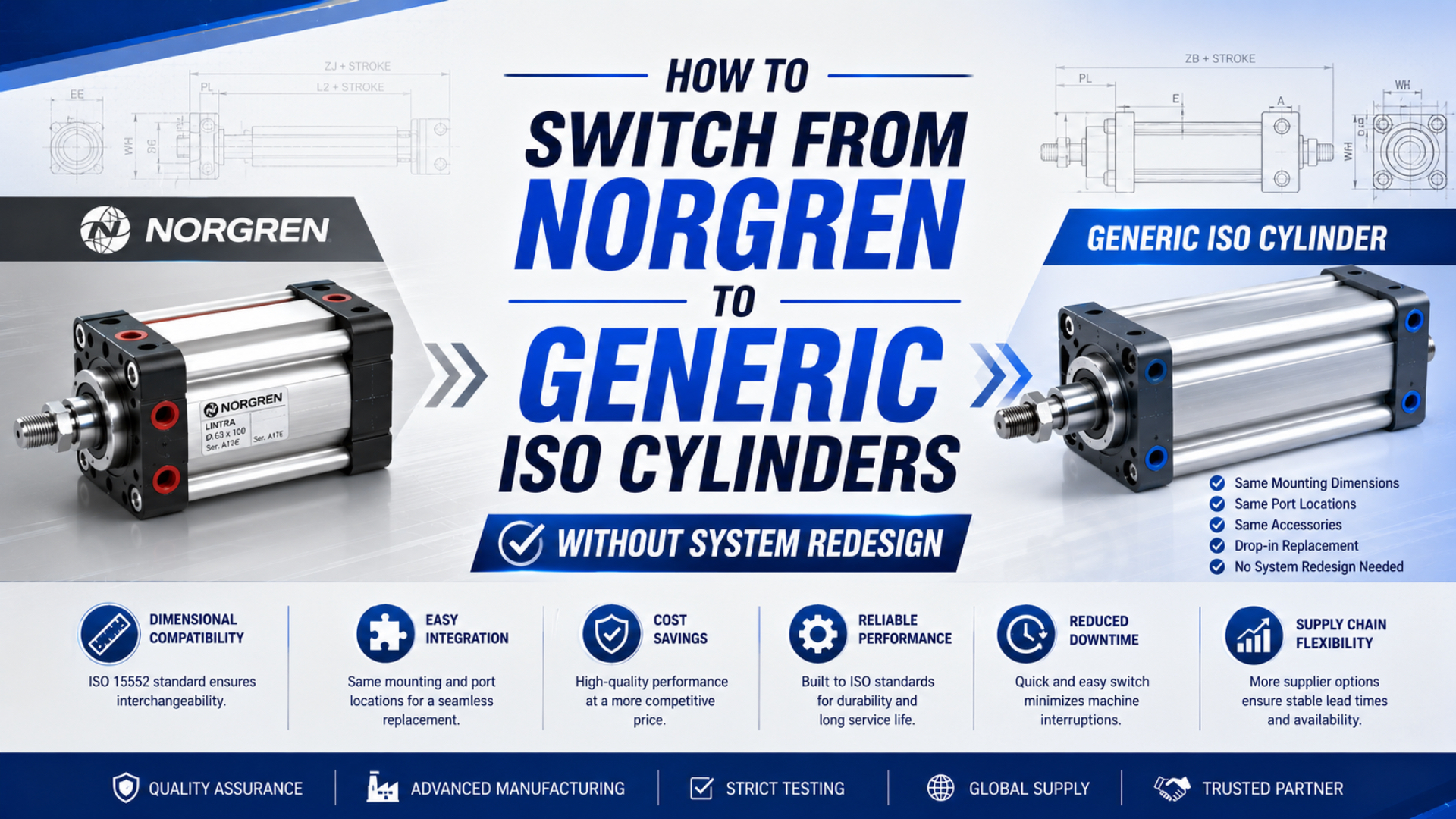
You can switch from a Norgren cylinder to another manufacturer’s ISO cylinder without redesign only when the installed unit belongs to the same ISO dimensional family and the proposed replacement passes drawing, configuration, performance, and machine-acceptance checks. The ISO mark is the start of the cross-reference, not approval to install.
Norgren cylinder replacement is the controlled substitution of an installed Norgren actuator with a documented alternative that preserves the machine’s required interfaces and duty. It is not a model-number guess or a brand-only purchasing decision.
ISO 15552:2018 establishes the basic, mounting, and accessory dimensions needed for interchangeability of detachable-mount cylinders from 32 to 320 mm bore. ISO 6432:2015 establishes mounting dimensions for commonly used 8 to 25 mm mini cylinders and explicitly leaves manufacturers freedom of design. Neither scope makes every port, sensor, seal, cushion, material, or operating characteristic identical (ISO 15552:2018; ISO 6432:2015).
Key Takeaways
- Record the complete Norgren part number before removing the cylinder.
- Confirm the ISO family from an official series document, not from its appearance.
- Overlay dimensioned drawings and check every installed interface.
- Recalculate push and pull force at the measured working pressure.
- Release the replacement only after a controlled first-article and machine test.
- Stop and redesign when any safety, load, mounting, sensing, or envelope requirement changes.
What Does “Without Redesign” Actually Mean?
A replacement requires no redesign when it preserves every machine-controlled interface and operating requirement. That is narrower than saying two cylinders share an ISO number.
From our analysis of the current ISO scopes and Norgren series documents, the recurring source of error is evidence ownership. A dimensional standard, a configured product drawing, and a machine test answer different questions.
Use three evidence owners:
| Evidence owner | What it can establish | What it cannot establish alone |
|---|---|---|
| ISO standard | Applicable bore range and standardized basic, mounting, or accessory dimensions | Exact selected ports, sensing, seals, cushioning, materials, speed, or service life |
| Supplier configuration | Model-specific drawing, part-code options, pressure range, materials, ports, rod end, sensing, and cushioning | Performance on your machine under its actual load and air supply |
| Machine validation | Installed fit, motion, timing, stopping behavior, leakage, sensing, and safe recovery | Continued supply of an unchanged part unless configuration and revision are controlled |
This boundary is especially important when a purchasing request says “generic ISO cylinder.” Generic should mean an approved alternative from a traceable manufacturer with a controlled drawing and configuration. It should not mean an unverified cylinder that merely resembles the installed unit.
For the general dimensional methodology, see the ISO 15552 cylinder interchangeability checklist. This article concentrates on the Norgren-specific evidence needed before that checklist can be applied.
How Do You Identify the Exact Norgren Cylinder?
Photograph the nameplate and all four sides before disconnecting anything. Record the complete part number exactly, including every slash, suffix, and option character. Also record:
- bore and stroke;
- mounting style and accessory part numbers;
- piston-rod diameter, thread, and usable thread length;
- pressure-port thread, position, and fitting clearance;
- magnetic-piston and switch details;
- cushion type and adjustment access;
- extended and retracted machine clearances;
- working pressure at the cylinder during motion;
- load direction, orientation, speed, and cycles per shift;
- environment, temperature, washdown, corrosion, and air-quality requirements.
Do not decode a Norgren order number by analogy. Use the official page or series document for the exact code. For example, Norgren identifies RM/92020/M/100 as a compact double-acting cylinder with a 20 mm bore and 100 mm stroke (Norgren RM/92020/M/100). This evidence is more reliable than assuming that every group of digits has the same meaning across RA, PRA, RM, or another family.
Norgren’s official RA/8000 data sheet describes RA/8000 and RA/8000/M as ISO 15552 cylinders with adjustable cushioning; the /M version adds a magnetic piston. The document lists model-specific ports, rod diameters, rod threads, pressure ranges, and materials across its bore range (Norgren RA/8000 data sheet).
The official PRA/182000 document also states ISO 15552 conformity. However, it describes a profile-barrel family with its own construction and options (Norgren PRA/182000 data sheet). Two Norgren families can therefore share an ISO dimensional basis without sharing the same construction or every catalog option. A supplier’s proposed alternative must cross-reference the actual installed part, not simply “a Norgren ISO cylinder.”
In our experience, a complete order-code photograph prevents more cross-reference errors than a body photograph alone. Keep both because the body view still reveals brackets, fittings, switches, and clearance constraints that the code may not capture.
If the label is unreadable, do not guess from body shape. Search maintenance records, purchase orders, CAD assemblies, spare-parts lists, and old quotations. If those records disagree, measure the isolated cylinder and ask both the original manufacturer and the proposed supplier to identify the series from the evidence package.
Which ISO Family Does the Installed Cylinder Use?
The two most common families in this replacement task have different scopes:
| Standard | Published dimensional scope | Practical first check |
|---|---|---|
| ISO 15552:2018 | Detachable-mount cylinders, 32-320 mm bore, single or double rod, with or without provision for magnetic sensors | Confirm the exact mounting style and compare basic, mounting, and accessory dimensions |
| ISO 6432:2015 | Commonly used single-rod mini cylinders, 8-25 mm bore | Confirm the round-body mini-cylinder family and compare its mounting dimensions |
ISO 6431 may appear on older Norgren literature. ISO lists ISO 6431:1992 as withdrawn and revised by ISO 15552, so a current cross-reference should use the present ISO 15552 family while retaining the legacy reference in the evidence trail (ISO 6431:1992).
Stop the cross-reference if the installed cylinder is custom, non-ISO, guided, tandem, locking, low-friction, high-temperature, corrosion-resistant, rodless, or otherwise outside the proposed alternative’s documented scope. A special option can change the replacement problem even when the base body belongs to an ISO family.
For a mini-cylinder-specific removal and installation workflow, use the ISO 6432 replacement guide.
If the Norgren unit belongs to the mini-cylinder family and you need candidate series from several manufacturers, use the ISO 6432 cross-reference guide. Keep the present article as the Norgren identity and release-control layer; use that guide for the wider brand-family comparison.
Overlay the Drawings Interface by Interface
Request dimensioned drawings for the installed Norgren configuration and the proposed replacement. A model-family brochure is insufficient when it combines several bores, mountings, strokes, or options.
Compare the drawings at a common scale and mark every machine-controlled interface:
- Mounting datum: hole pattern, pilot diameter, flange face, clevis pin, trunnion axis, foot height, and fastener access.
- Stroke datums: retracted rod position, extended rod position, tolerance, and any adjustable stop.
- Rod connection: diameter, thread designation, thread length, shoulder position, wrench flats, and attached joint.
- Air connections: thread standard, port size, port face, orientation, fitting envelope, and tube bend radius.
- Sensing: magnetic piston, switch technology, groove or bracket, cable exit, connector, voltage, output type, and switching position.
- Cushion controls: cushion type, adjustment range, screw access, and clearance for commissioning.
- Body envelope: cap shape, tie rods or profile, protrusions, sensor cable, fittings, and maintenance-tool access.
Do not hide a mismatch with an adapter until engineering has classified it. A rod adapter changes stack length and may increase overhung moment. A port adapter can collide with guarding or add dead volume. A new sensor bracket can shift the switching window. Those may be acceptable design changes, but they are not a no-redesign replacement.
Use the piston-rod end thread guide when the rod connection needs a separate interface review.
How Do You Verify Force and Operating Duty?
Equal bore and stroke do not prove equal installed performance. Begin with theoretical force at the lowest pressure measured while the cylinder is moving:
where (P) is gauge pressure at the active cylinder port, (D) is bore diameter, and (d) is rod diameter. Keep units consistent. These equations do not include seal friction, pressure loss, acceleration, side load, backpressure, or uncertainty, so they are screening values rather than guaranteed machine force.
Then compare the configured ratings and the application:
- allowable working pressure and proof-test information;
- theoretical push and pull force at the same pressure;
- permitted speed range and low-speed behavior;
- cushioning type and available cushion adjustment;
- moving mass, external load, orientation, and gravity;
- side load or moment and the need for an external guide;
- cycle rate, dwell, thermal conditions, and air quality;
- leakage criteria and loss of pressure behavior;
- seal, rod, barrel, and end-cap materials;
- environmental and regulatory requirements.
Do not import a universal cycle-life claim into the comparison. ISO 19973-3 specifies procedures for assessing and reporting the reliability of piston-rod cylinders; it does not assign one lifetime to every conforming product (ISO 19973-3:2015). If life matters to the risk decision, request test conditions, sample size, failure definition, statistical result, and evidence for the exact product family.
Speed deserves its own check. A cylinder’s motion depends on the valve, fittings, tubes, supply pressure, exhaust path, load, and cushioning as well as the cylinder. If the replacement changes port size, internal volume, cushion design, or friction, repeat the timing test instead of assuming the old setting will transfer.
Inspect and Test a First Article
Order a sample only after the document comparison is complete. The purchase description should freeze the manufacturer, complete part number, revision or drawing, bore, stroke, mounting, ports, rod end, magnetic option, switches, cushioning, seals, materials, and required documentation.
Before installation, inspect the first article against the approved drawing:
- verify the label and complete order code;
- measure the machine-controlled dimensions;
- inspect threads, sealing faces, rod condition, and mounting surfaces;
- confirm switch, cable, connector, and bracket details;
- check cushion adjusters and port access;
- record the supplied materials and pressure ratings;
- photograph the inspected configuration.
Define acceptance tolerances from the machine drawing, supplier drawing, applicable standard, and risk assessment. Do not borrow arbitrary tolerances from a generic blog checklist. ISO 10099 provides final examination and acceptance criteria for pneumatic cylinders, but the machine owner still needs application-specific release criteria (ISO 10099:2001).
Installation and testing must follow the site’s hazardous-energy procedure. OSHA identifies pneumatic energy as hazardous energy and requires control where unexpected startup or release of stored energy could injure workers (OSHA, Control of Hazardous Energy).
After isolation, venting, restraint of gravity loads, installation, and guarded restart, test:
| Test | What to record | Pass basis |
|---|---|---|
| Static fit | Mounting seating, alignment, rod connection, fitting and sensor clearance | Approved drawing and machine envelope |
| Leakage | External leakage and unintended position change under defined pressure and dwell | Site and application acceptance criteria |
| Motion | Full stroke, freedom from binding, extend/retract time, repeatability | Baseline machine requirement |
| Force function | Ability to move, clamp, lift, or return the real load | Documented operating requirement and margin |
| Cushioning | End-of-stroke behavior, rebound, noise, adjustment position | Equipment limit and stable stopping behavior |
| Sensing | Switching position, repeatability, PLC input, cable routing | Control sequence and diagnostic requirement |
| Safety response | Isolation, venting, restart, loss-of-air behavior, guarding | Site risk assessment and validated procedure |
Do not begin with a long production run. First prove controlled low-speed motion, then normal motion, then the defined production observation period. Record the test conditions so the result can be repeated.
When Should You Stop and Redesign?
The following flow prevents a commercial cross-reference from becoming an uncontrolled engineering change.
Redesign is required when the replacement needs new holes, a changed bracket, a rod adapter that alters geometry, different fittings that affect clearance, a sensor or PLC change, revised cushioning, a different load path, or altered guarding. It is also required when the original application lacks enough data to prove force, stability, environmental compatibility, or safe failure behavior.
Build a Reorderable Cross-Reference
After a successful test, preserve the evidence. The approved cross-reference record should contain:
- old Norgren part number and installed configuration;
- replacement manufacturer and complete part number;
- approved drawings and revisions;
- dimensional inspection report;
- datasheets and conformity statements;
- force and duty review;
- first-article and machine-test results;
- photographs of the accepted sample;
- approved switches, accessories, fittings, and mounting hardware;
- change-control owner and revalidation triggers.
Mark the replacement as approved only for the specific application or clearly defined application family that was tested. Do not automatically propagate one successful cross-reference to every cylinder with the same bore.
For a facility-wide program, connect these records to the pneumatic cylinder standardization framework. For purchasing requirements, use the ISO 15552 cylinder procurement checklist.
When requesting an alternative, send evidence rather than asking for “the equivalent.” A useful RFQ includes the original code, photographs, dimensioned drawing, operating pressure, load, orientation, cycle requirement, environment, switches, and accessories. It should also state the expected documentation, inspection characteristics, and acceptance test. Require the supplier to identify every deviation instead of silently resolving it with a “nearest” model.
Norgren-to-Generic ISO Cylinder FAQs
Does the same ISO number guarantee a drop-in Norgren replacement?
No. It establishes a defined dimensional family, but the selected cylinder can still differ in ports, rod end, sensors, cushioning, seals, materials, pressure rating, envelope, and operating behavior. Approve the replacement only after comparing configured drawings and completing the machine test.
Can I identify the bore and stroke from the Norgren part number alone?
Only when the official Norgren document or product page explains that exact series and code. Do not transfer a decoder from one family to another. Record the complete code and verify it against controlled manufacturer information.
Can I reuse the existing Norgren mounting accessories?
Possibly, when the accessory interface and the proposed cylinder drawing match. Check the exact flange, foot, clevis, trunnion, pin, fasteners, and installed clearances. An ISO family name alone does not prove that every existing accessory is suitable for the selected configuration.
Is a cheaper ISO cylinder automatically equivalent?
No. Price does not establish dimensional, functional, environmental, or reliability equivalence. Compare the controlled configuration, supplier documentation, inspection result, machine test, availability, change notification, and lifecycle requirements before comparing commercial terms.
When must the switch be treated as a redesign?
Treat it as a redesign whenever the replacement changes a machine interface, load path, control signal, motion behavior, safety function, environmental capability, or validated operating limit. Unknown critical requirements are also a stop condition until they are measured or recovered from engineering records.
The practical way to leave a proprietary purchasing path is not to assume that all ISO cylinders are identical. Instead, turn the installed Norgren cylinder into a verified interface specification. Then qualify one exact alternative and preserve the evidence so the same approved configuration can be reordered. For publisher and engineering-team context, see About Bepto.
External technical references and retrieval dates
ISO 15552:2018: Scope, bore range, pressure series, and basic, mounting, and accessory dimensions for interchangeability. Confirmed 2025; retrieved 2026-07-26.
ISO 6432:2015: Scope, bore range, mounting dimensions, and manufacturer design freedom for mini cylinders. Retrieved 2026-07-26.
ISO 6431:1992: Withdrawn legacy standard and its revision path to ISO 15552. Retrieved 2026-07-26.
Norgren RA/8000 data sheet: ISO family, operation, bore range, ports, rod sizes, rod threads, pressure, cushioning, and materials. Retrieved 2026-07-26.
Norgren PRA/182000 data sheet: ISO family and model-specific profile-cylinder configuration data. Retrieved 2026-07-26.
Norgren RM/92020/M/100 product page: Exact Norgren model identity, 20 mm bore, and 100 mm stroke. Retrieved 2026-07-26.
ISO 19973-3:2015: Reliability assessment test procedures and reporting for piston-rod cylinders. Retrieved 2026-07-26.
ISO 10099:2001: Final examination and acceptance criteria for pneumatic cylinders. Retrieved 2026-07-26.
OSHA, Control of Hazardous Energy: Pneumatic energy as hazardous energy and lockout/tagout responsibilities. Retrieved 2026-07-26.