

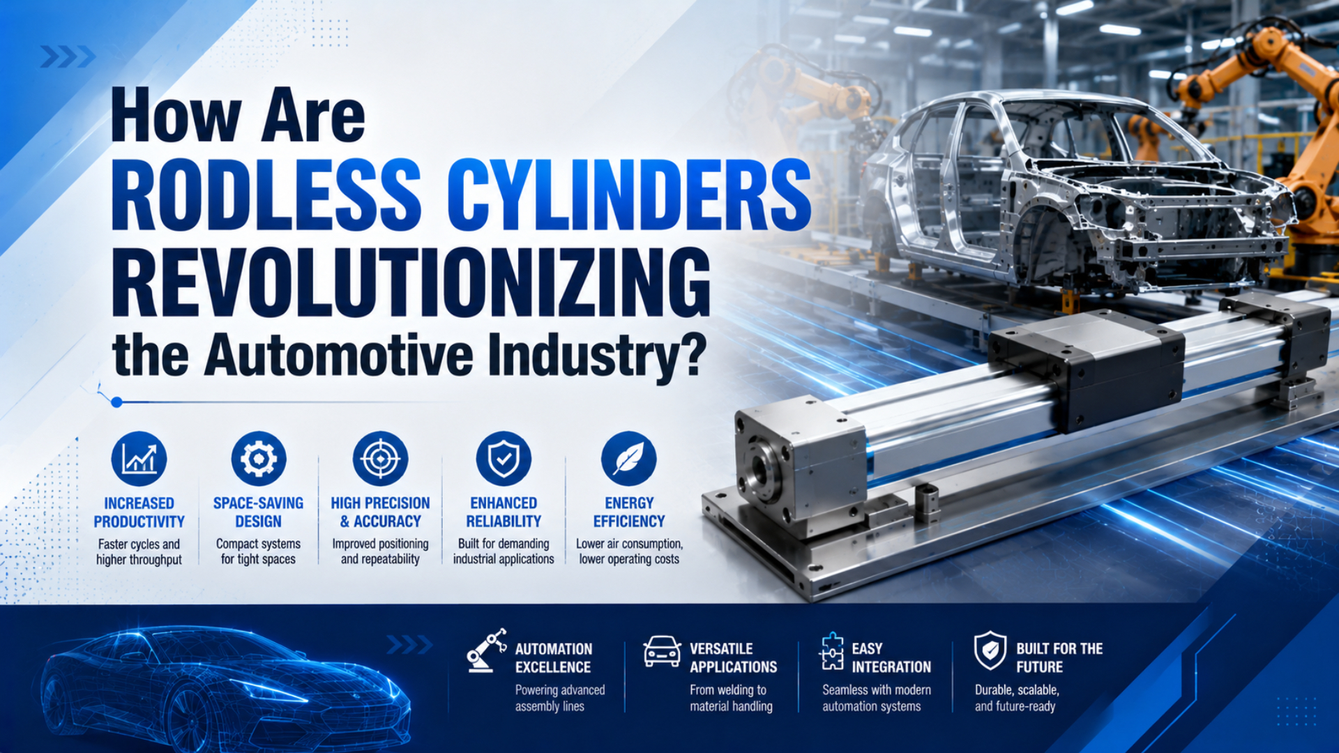
Rodless cylinders improve automotive production when a long, repetitive linear move must fit inside a short machine envelope. They are useful for part presentation, transfer, clamping support, door or fixture motion, and selected handling tasks. The gain comes from moving a carriage along the cylinder body instead of extending a piston rod beyond it.
That compact geometry does not guarantee welding resistance, precision, cleanroom suitability, or safe stopping. Those results depend on the complete axis: cylinder architecture, guide, load center, valve and tubing, end-of-stroke protection, sensors, mounting surface, guarding, and loss-of-pressure behavior.
Parker lists its OSP-P family in eight bore sizes from 10 to 80 mm, with standard strokes up to 6,000 mm and a maximum operating pressure of 8 bar (Parker OSP-P Series, accessed 2026). Those figures show the design range available, but the automotive task still determines whether a pneumatic rodless axis is the right choice.
Key Takeaways
- Parker lists OSP-P strokes up to 6,000 mm for point-to-point and transfer duties.
- A welding-area actuator needs verified protection from spatter, not just a compact body.
- Sensors confirm position; they do not create servo accuracy.
- Clean-series components still require equipment-level particle qualification.
Automotive Plant Applications for Rodless Cylinders
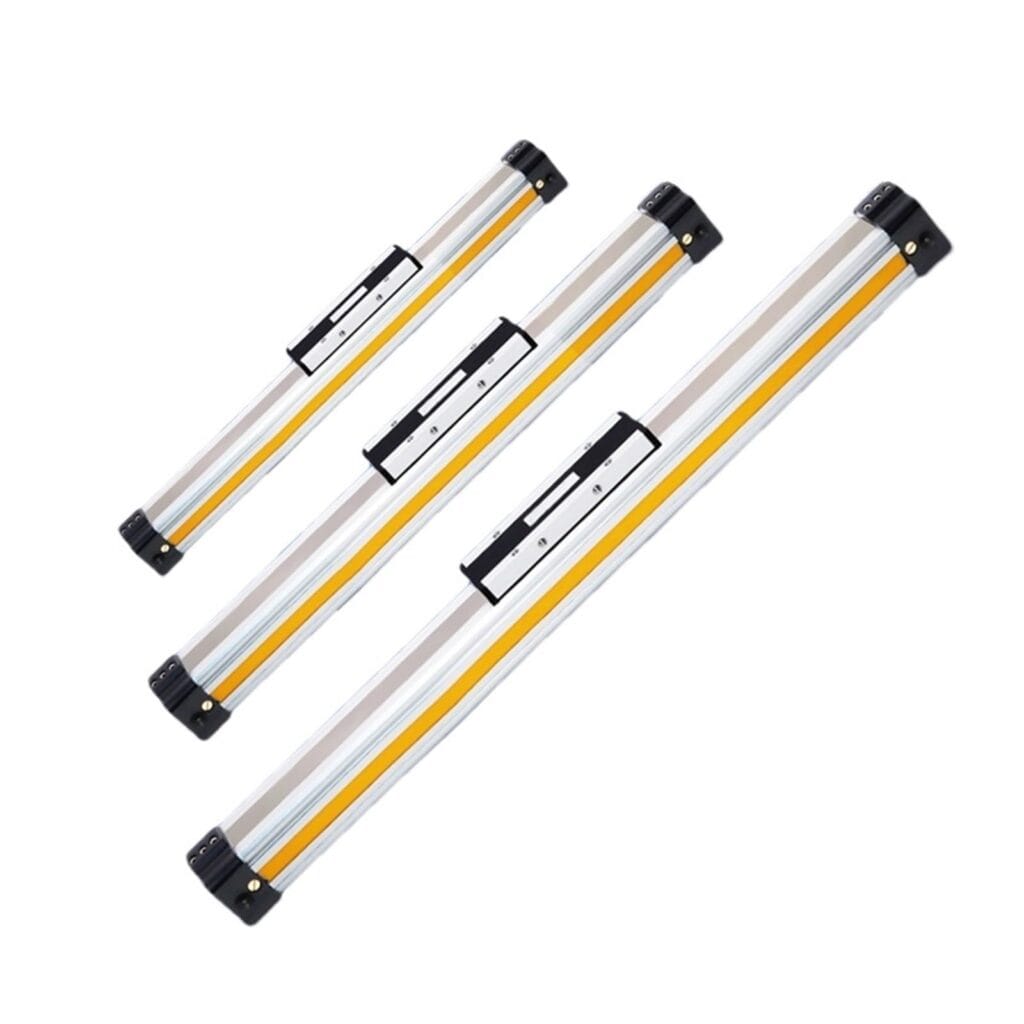
Parker describes the OSP-P as a point-to-point, reciprocating, and simple traverse or transfer actuator, with eight cataloged bore sizes and strokes up to 6,000 mm (Parker OSP-P Series, accessed 2026). That makes it a practical candidate for bounded linear motion, not a universal substitute for every robot or servo axis.
The best applications have two characteristics. First, the axis has defined end positions or a small number of mechanically established stops. Second, eliminating the projecting piston rod solves a real layout problem. Typical examples include moving a fixture under a station, presenting a door component to an operator, transferring a tray between processes, or opening and closing an access panel.
Rodless geometry can also simplify guarding. The moving element stays on the cylinder body, so the designer does not need a separate envelope for an emerging rod. Still, the carriage, load, cable carrier, and attached tooling remain moving hazards. Compact does not mean inherently safe.
Use the application zone only as a starting filter:
| Automotive zone | Suitable rodless-cylinder tasks | Main design gates | Common rejection trigger |
|---|---|---|---|
| Body-in-white | Fixture shuttle, part presenter, guarded transfer, access motion | Spatter shielding, guide moments, stopping energy, maintainability | Direct spatter exposure without manufacturer approval |
| General assembly | Tray transfer, dashboard or door-part presentation, test-station motion | Stroke time, hard-stop repeatability, load center, cable routing | Many programmable positions or continuous contouring |
| Battery and electronics | Clean-compatible transfer, enclosure handling, inspection positioning | Particle testing, material compatibility, exhaust routing, external guide | Assuming a component label proves the installed axis class |
| End-of-line testing | Reciprocating load, durability fixture, simple traverse | Duty cycle, cushion energy, bearing life, loss-of-pressure state | Motion profile exceeds pneumatic control capability |
For a broader cross-industry view, see where rodless cylinders are used. Automotive selection is narrower because contamination, weld debris, takt time, quality verification, and recovery after a fault often govern the decision.
The useful design question is not “Can a rodless cylinder move this part?” It usually can. Ask whether the axis can move the part through every production and fault condition while keeping its guide load, stop energy, contamination, and recovery behavior inside documented limits.
Rodless Cylinders in Body-in-White Areas
SMC offers its ML1C mechanically jointed rodless cylinder with brake in 25, 32, and 40 mm bores, yet the same catalog warns against exposure to spatter, dust, cutting chips, or cutting fluid (SMC ML1C Catalog, pp. 949, 961). Welding-area suitability therefore needs a protected installation, not a generic product-family assumption.

The body shop is a demanding location for exposed linear hardware. Weld spatter, conductive dust, sharp sheet edges, vibration, coolant or cleaning fluid, and frequent maintenance work can damage a sealing band, scraper, bearing, or sensor cable. If the selected manufacturer excludes those contaminants, a nearby welding robot does not make the actuator “welding rated.”
A rodless cylinder can still serve protected auxiliary motion around a welding cell. Examples include moving a guarded fixture outside the direct spatter cone, presenting a component behind shielding, operating a maintenance door, or shifting a fixture beneath a cover. The cylinder should be positioned so debris cannot accumulate on its sealing interface or guide.
Treat shielding as part of the actuator
Specify the cover material, overlap, service access, and debris path. A flat cover directly above the carriage may catch spatter and turn maintenance into a scraping job. A sloped shield with enough clearance for the cable carrier usually manages debris better. Confirm that the shield does not trap heat or block the cylinder’s inspection points.
Include cables and hoses in the moment calculation
SMC tells designers to include external forces from piping and cable carriers when selecting allowable moments (SMC ML1C Catalog, p. 961). This matters in welding cells, where dress packs can become stiff, contaminated, or misrouted. Their force changes across the stroke and can load the carriage even when the tooling itself is centered.
Keep weld quality separate from cylinder repeatability
A rodless axis may present a fixture or gun-support mechanism, but weld quality depends on the complete stack: tooling stiffness, locating pins, part variation, gun calibration, robot path, electrode condition, clamp force, and process controls. Position switches on the cylinder can provide an interlock. They do not prove the weld location or electrode force.
What Changes in General Assembly and Part Presentation?
Parker lists OSP-P theoretical thrust from 47 to 3,010 N at 6 bar and equal extend and retract force because the actuator has no piston rod area difference (Parker OSP-P Series, accessed 2026). That symmetry suits repetitive transfers, but available force at the load still depends on pressure losses, friction, acceleration, and guide resistance.
General assembly usually offers the clearest fit. The environment is often less aggressive than the body shop, while long strokes and tight equipment spacing remain common. A rodless carriage can move a nest, tray, support frame, scanner, tool balancer, or lightweight fixture between fixed positions.
The axis should be designed around the station’s functional sequence:
- Define the load at the carriage, including fixture, workpiece, hoses, cable chain, and any operator-added item.
- Record the horizontal and vertical distance from the carriage reference plane to the combined center of mass.
- State the required travel and usable dwell positions.
- Set the allowed move time, settling time, and maximum impact at the stop.
- Decide how the PLC will verify that the station is ready for the next operation.
- Define the safe state during air loss, electrical loss, emergency stop, and manual recovery.
Mechanical stops often determine the final position in a pneumatic assembly axis. The cylinder provides motion, while the stop, nest, pin, or fixture establishes the process datum. That distinction prevents teams from assigning a part-fit tolerance directly to a switch-equipped cylinder.
For force screening, use the piston area and effective pressure, then subtract realistic losses. The detailed method is covered in cylinder force loss due to friction and back pressure. For cycle-time work, valve flow, tube size, stroke volume, and exhaust restriction must be checked together.
Can Rodless Cylinders Meet Automotive Positioning Requirements?
SMC states that its ML1C rodless cylinder does not guarantee traveling parallelism and notes that slight speed variation can occur because of the seal structure (SMC ML1C Catalog, p. 961). A sensor-ready carriage is therefore not evidence of micron-level path accuracy or closed-loop servo performance.
Three different specifications are often mixed together:
- End-position repeatability asks how consistently the mechanism returns to the same stop under stated load, pressure, speed, and temperature.
- Travel straightness or parallelism describes the path of the carriage over the stroke.
- Process accuracy is the error at the part, tool, camera, or joint after every structural and control error is combined.
A magnetic switch can confirm that a piston or carriage entered a sensing zone. An analog position sensor can report position over the stroke. Neither one eliminates compressible-air behavior, seal friction, structural deflection, guide clearance, pressure variation, or stop compliance. Closed-loop control requires a suitable feedback device, valve, controller, tuning method, and mechanical plant.
When a process position must be precise, use an external datum whenever possible. Let a hardened stop, locating pin, nest, or clamp set the final relationship to the part. Use the cylinder to approach that datum at controlled speed. Then use independent sensors to confirm both actuator state and part state.
Long strokes also amplify mounting errors. SMC recommends a floating connection when an externally supported load is attached over a long stroke because center-axis variation grows with length (SMC ML1C Catalog, p. 961). The related guide-rail parallelism tolerance stack-up deserves its own review before the frame is released.
Clean-Area Qualification for Battery and Electronics
ISO 14644-1 classifies air cleanliness using airborne particle concentrations from 0.1 to 5 µm, while ISO 14644-14:2026 defines a method for assessing equipment suitability in cleanrooms (ISO 14644-1, 2015; ISO 14644-14, 2026). Neither standard makes a complete axis compliant merely because one cylinder is sold as a clean series.
SMC’s 12-CY3 clean-series rodless cylinder is offered in nine bore sizes from 6 to 63 mm, but its guide is non-integrated (SMC 12-CY3, accessed 2026). The guide, brackets, fasteners, tubing, sensor cables, lubricants, exhaust treatment, and moving payload therefore remain part of the qualification.
For battery and electronic-component areas, build the requirement from the process:
- State the controlled-zone classification and the particle sizes that matter.
- Define where exhaust air goes and whether local extraction is required.
- Identify prohibited materials, lubricants, surface treatments, and cleaning chemicals.
- Specify whether the process has dry-room, electrostatic-discharge, chemical, or flammability constraints beyond particle cleanliness.
- Test the assembled axis through its intended stroke, speed, load, and duty cycle.
- Measure at representative locations and operating states, not just beside an idle component.
A magnetically coupled cylinder avoids a longitudinal mechanical slot through the pressure tube, which can help in some clean designs. It can also decouple if the required thrust or external disturbance exceeds the magnetic coupling force. An external guide is still needed when the load produces side force or moment.
Clean selection is an equipment problem with a component starting point. The clean-series label narrows the candidate list; the installed-axis test decides whether the design belongs in the controlled process. This distinction is especially useful in battery projects, where particle, humidity, chemical, and electrical requirements may coexist but are verified by different methods.
For a component-focused review, see pneumatic cylinders for critical cleanroom environments.
Which Rodless Cylinder Architecture Fits Each Automotive Task?
Parker’s mechanically coupled OSP-P range spans eight bores from 10 to 80 mm, while SMC’s clean-series 12-CY3 magnetically coupled range spans nine bores from 6 to 63 mm (Parker OSP-P Series; SMC 12-CY3, accessed 2026). Those ranges illustrate why architecture must be chosen before bore size.
| Architecture | Strength | Constraint | Automotive use case |
|---|---|---|---|
| Mechanically coupled, basic carriage | Direct mechanical connection and compact long stroke | Seal-band interface needs environmental review; external guide may be required | Protected horizontal transfer with an independently guided load |
| Mechanically coupled, integrated guide | Guide and actuator supplied as one assembly | Model-specific pitch, yaw, and roll limits still apply | Fixture or nest transfer with a defined offset load |
| Magnetically coupled | Pressure tube remains unslotted; carriage can decouple under overload | Coupling force limits thrust; load still needs guidance | Clean-compatible light transfer or simple enclosure motion |
| Guided cylinder with brake or lock | Can provide holding or intermediate-stop functions | Holding force, dynamic stop behavior, and circuit requirements are model specific | Vertical or fault-sensitive axis after a formal risk review |
| Servo-pneumatic package | Adds continuous feedback and controlled positioning | More tuning, valve capacity, air-quality, and control complexity | Limited variable-position tasks where pneumatic architecture remains justified |
Mechanically coupled cylinders usually provide higher usable thrust for a given envelope because the piston and carriage are physically linked. Their sealing-band path must remain protected and serviceable. Magnetically coupled designs remove that mechanical connection, but “breakaway” becomes a selection limit. Learn how that limit behaves in magnetic de-coupling force analysis.
A guided model is not automatically immune to off-center loading. Catalogs normally separate pitch, yaw, and roll moments and may reduce allowable load as speed or mounting orientation changes. The correct comparison uses the same load center, speed, stroke, stop method, and duty cycle for every candidate.
What Calculations Prevent the Most Common Selection Errors?
SMC’s ML1C selection method requires the combined load ratios for mass, static moment, and dynamic moment to total no more than 1 (SMC ML1C Catalog, p. 950). That catalog-specific method captures a key principle: bore force alone cannot validate an automotive rodless axis.
Start with the installation envelope. Compare the complete actuator length at the required stroke, including end caps, adjusters, shock absorbers, brackets, sensor connectors, valve blocks, cable carrier bend radius, and service clearance. Never convert the absence of a projecting rod into a universal percentage saving. Use the actual dimensional drawings.
Next, calculate each applied moment from force and offset:
Here, is the applied moment in N·m, is the relevant force in N, and is the perpendicular distance from the guide reference to that force in m. Repeat the calculation for pitch, yaw, and roll as defined by the candidate catalog. Include gravity, acceleration, tooling reactions, hose forces, and cable-carrier forces.
If several load components act together, use the manufacturer’s combined-load equation. Do not invent a universal rule from one product catalog. Model A may combine moment ratios linearly, while model B may impose separate graphs or orientation-dependent limits.
Stopping energy deserves a separate check:
Here, is kinetic energy in J, is total moving mass in kg, and is speed immediately before deceleration in m/s. The equation covers translational kinetic energy only. Add driven tooling effects, vertical potential, external forces, and safety margin according to the cushion or shock-absorber manufacturer’s method.
Speed matters twice. It changes fill and exhaust requirements, and its square changes kinetic energy. Doubling approach speed makes the translational kinetic energy four times larger at the same mass. That is why a cylinder that passes a static force check can still fail at the end of stroke.
Review internal air-cushion energy limits when the cylinder’s cushion is expected to stop the load. If the load or takt target is close to the catalog boundary, use an external stop or shock absorber sized for the actual impact conditions.
When Is an Electric or Servo-Pneumatic Axis the Better Choice?
Parker positions the OSP-P for point-to-point, reciprocating, and simple traverse or transfer work, even though the family reaches 6,000 mm standard stroke (Parker OSP-P Series, accessed 2026). Stroke capability is not motion-control capability. Variable profiles and process-path accuracy can shift the decision toward electric or servo-pneumatic technology.
Choose an electric axis when the application needs many programmable positions, coordinated interpolation, controlled force over travel, recipe changes without mechanical stops, or detailed motion diagnostics. Electric actuation may also be preferable when compressed air is unavailable, air consumption is unacceptable, or the process needs slow, constant motion that a basic pneumatic circuit cannot hold reliably.
Servo-pneumatic motion can occupy the middle ground. It combines a pneumatic actuator with continuous position feedback, a proportional valve, and a suitable controller. It may fit applications that benefit from pneumatic power density but need more than end switches. It also brings tuning sensitivity, air-quality requirements, valve-flow limits, and a more involved commissioning process.
Use a conventional rodless cylinder when the motion is fundamentally simple and the mechanical system can establish the important datums. Do not buy a control problem because the actuator envelope looks attractive.
The comparison should include the complete installed system:
| Decision factor | Basic pneumatic rodless axis | Servo-pneumatic axis | Electric linear axis |
|---|---|---|---|
| Best motion | Two-position or few-stop transfer | Controlled multi-position pneumatic motion | Many positions and programmable profiles |
| Final datum | Usually mechanical stop or fixture | Feedback plus controller, sometimes stop | Encoder and servo control |
| Utilities | Compressed air and electrical valve control | Clean stable air plus control electronics | Electrical supply and drive |
| Fault behavior | Depends on valve, load orientation, brake, and circuit | Depends on controller, valve, brake, and stored air | Depends on brake, drive safety functions, and mechanics |
| Commissioning effort | Low to moderate | Moderate to high | Moderate to high |
What Should an Automotive Rodless-Cylinder RFQ Include?
Parker specifies up to 8 bar operating pressure, 47 to 3,010 N force at 6 bar, and strokes up to 6,000 mm for the OSP-P family (Parker OSP-P Series, accessed 2026). Those catalog limits are useful context, but a supplier cannot select the axis responsibly from bore and stroke alone.
Send enough information to reproduce the load case. A short RFQ with “500 mm stroke, 50 kg load” leaves out the variables that usually cause trouble.
| RFQ field | What to provide | Why it matters |
|---|---|---|
| Motion | Orientation, stroke, direction, usable positions, move and dwell time | Establishes the duty and control method |
| Load | Moving mass plus tooling, workpiece, cables, hoses, and variable payload | Sets thrust, guide load, and energy |
| Load center | Offsets in all three axes, with a sketch | Allows pitch, yaw, and roll calculations |
| External forces | Process reaction, clamp force, cable carrier, vacuum hose, operator load | Prevents hidden carriage loading |
| Environment | Spatter, dust, fluid, temperature, cleaning agents, controlled-zone needs | Determines sealing, shielding, materials, and qualification |
| Stops | Internal cushion, external shock absorber, hard stop, brake, or lock | Determines energy absorption and fault behavior |
| Air supply | Minimum pressure at the valve during the move, air quality, tube length and ID | Supports real force and timing estimates |
| Controls | Valve type, sensors, required feedback, PLC interface, stop categories | Defines the automation architecture |
| Mounting | Base flatness, support spacing, external guide, floating connection | Protects alignment and sealing |
| Life target | Cycles per minute, shifts, days per year, planned service interval | Supports durability and spare-parts planning |
| Safety state | Behavior on air loss, power loss, emergency stop, and restart | Drives brake, lock, dump, and recovery decisions |
Attach a dimensioned layout. Mark the carriage reference, load center, cable-carrier anchor, hard stops, and maintenance access. If the axis is vertical, state whether the load may fall or drift when pressure is removed. If it enters a guarded cell, define the risk-reduction function separately from ordinary motion control.
How Should Commissioning and Maintenance Be Planned?
SMC instructs users to place the ML1C brake valve close to the cylinder because excessive distance can vary stopping accuracy or cause sudden table movement (SMC ML1C Catalog, p. 951). This is a useful reminder that tubing layout can alter machine behavior after component selection is complete.
Commission the axis at reduced speed and pressure where the risk assessment permits. Confirm free travel before connecting the production load. Check that the mounting surface does not twist the cylinder body, that an externally guided load does not bind, and that cables or hoses do not pull the carriage toward a moment limit at either end.
Then validate the actual sequence:
- Record pressure at the valve and cylinder during the fastest move.
- Measure move time and impact speed with the production payload.
- Verify the final datum, sensor state, and PLC timeout over repeated cycles.
- Test controlled stop, air isolation, electrical loss, emergency stop, and restart.
- Confirm that stored pneumatic energy is released or retained as the safety design requires.
- Inspect the shield and debris path after representative production exposure.
Maintenance frequency should come from the chosen product manual and measured operating conditions. A kilometer rating, cycle rating, or shock-absorber replacement interval applies only under its stated conditions. Temperature, contamination, impact energy, lubrication, side load, pressure quality, and mounting error can all shorten the interval.
Create access for sealing-band inspection, guide cleaning, sensor adjustment, cushion adjustment, and shock-absorber replacement. Keep a baseline for move time, stop behavior, leakage, and carriage play. Trend changes rather than waiting for a line stop.
The rodless-cylinder preventive maintenance checklist can help structure those inspections after the model-specific manual has set the limits.
The Automotive Advantage Comes From a Better-Fitted Axis
Parker’s OSP-P range combines eight bore sizes, up to 6,000 mm standard stroke, and modular guide, brake, valve, and cleanroom options (Parker OSP-P Series, accessed 2026). That breadth explains the automotive opportunity. The result still depends on choosing a configuration that fits the task instead of the industry label.
Rodless cylinders are strongest in compact point-to-point transfers where the carriage layout solves a genuine packaging problem. They can serve protected body-shop auxiliary motion, general-assembly presentation, test fixtures, and selected clean-compatible transfers. They are weaker when the application demands direct spatter exposure, unverified cleanroom claims, high path accuracy, many programmable positions, or uncontrolled off-center loads.
The practical payoff is not a universal footprint percentage or cycle-time claim. It is a machine whose dimensions, moments, stop energy, controls, environment, and fault behavior have all been checked against current catalog data and then validated in the complete station.
Automotive Rodless Cylinder FAQs: What Should Engineers Ask?
Parker lists OSP-P forces up to 3,010 N at 6 bar, while SMC’s ML1C selection method requires combined mass and moment load ratios to remain at or below 1 (Parker OSP-P Series; SMC ML1C Catalog, accessed 2026). These FAQs turn those catalog principles into practical screening questions.
Are rodless cylinders suitable for direct exposure to welding spatter?
Not by default. SMC explicitly warns that its ML1C should not be exposed to spatter, dust, cutting chips, or cutting fluid. A rodless cylinder can support protected auxiliary motion near welding, but the selected model, shield, mounting orientation, debris path, and maintenance access must be approved for the actual environment.
Can a rodless cylinder position an automotive component accurately?
It can repeat a controlled move, but process accuracy depends on the complete mechanical and control chain. SMC states that ML1C travel parallelism is not guaranteed. Use mechanical datums for critical assembly positions, calculate structural deflection and guide clearance, and validate repeatability at the part under production load, speed, pressure, and temperature.
Does a clean-series rodless cylinder guarantee an ISO cleanroom class?
No. ISO 14644-1 classifies air cleanliness in rooms and zones, while ISO 14644-14:2026 addresses equipment suitability assessment. A clean-series cylinder is one component. The guide, fasteners, lubricant, tubing, exhaust, cables, payload, cleaning method, speed, and duty cycle must be evaluated as an installed axis.
How do engineers choose between mechanically and magnetically coupled designs?
Choose from the load and environment. A mechanically coupled design provides a direct piston-to-carriage connection but exposes a sealing-band interface that needs protection. A magnetic design keeps the pressure tube unslotted, yet its coupling can separate under excessive thrust or disturbance. Both need model-specific guide and moment checks.
When should an automotive team choose an electric axis instead?
Choose electric motion when the station needs many programmable positions, coordinated motion, continuous force or speed control, recipe changes, or process-path accuracy. Parker describes the OSP-P primarily for point-to-point and simple transfer work. A basic pneumatic rodless cylinder is strongest when stops or fixtures establish the important production datums.
Sources and technical references
- Parker OSP-P Rodless Cylinder Series: bore range, force, stroke, pressure, modular options, and intended motion types.
- SMC ML1C Mechanically Jointed Rodless Cylinder with Brake: moment selection, circuit notes, alignment, environment, and parallelism precautions.
- SMC 12-CY3 Clean-Series Magnetically Coupled Rodless Cylinder: clean-series designation, guide arrangement, and bore range.
- ISO 14644-1:2015: classification of air cleanliness by airborne particle concentration.
- ISO 14644-14:2026: equipment-suitability assessment methodology for airborne particle cleanliness.