

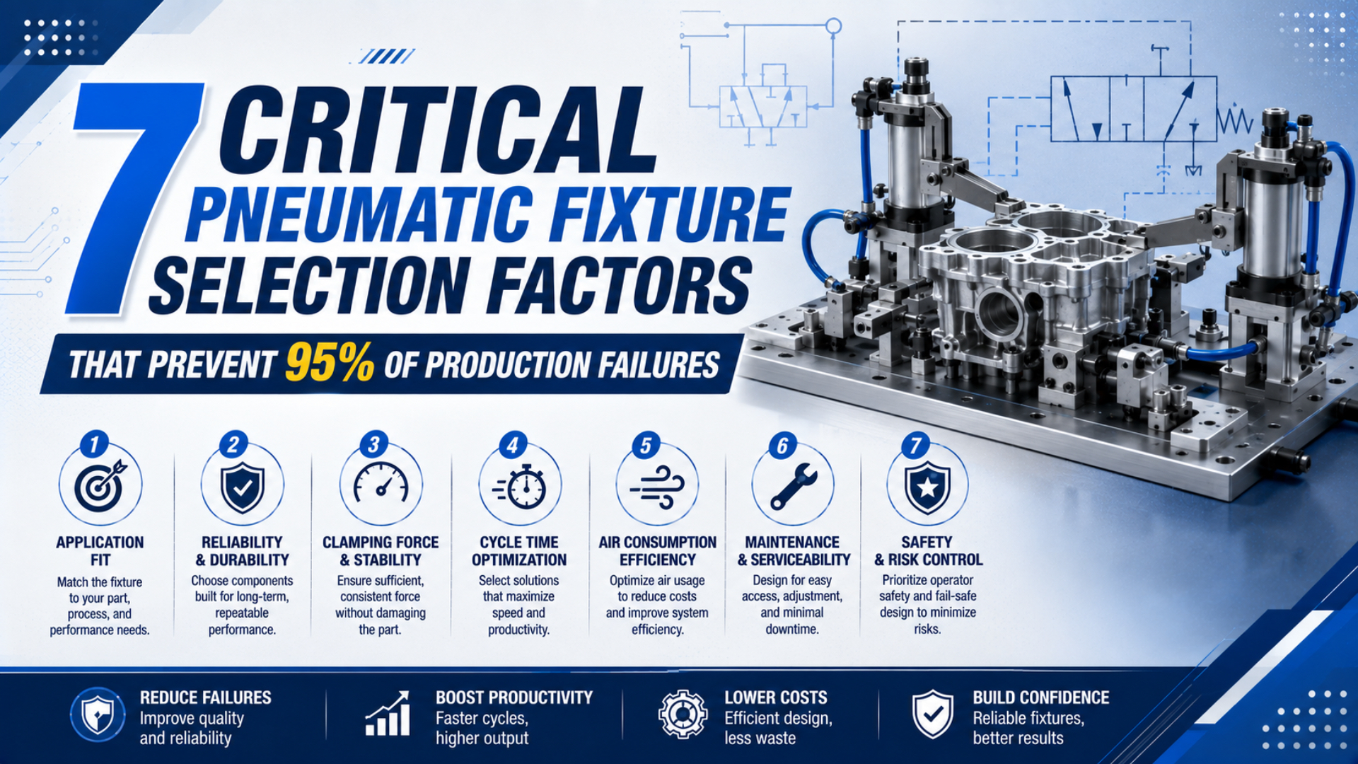
Pneumatic fixture selection should begin with the load path, not a cylinder bore or catalog clamping-force headline. A suitable fixture must hold the workpiece against defined locators at the lowest expected point-of-use pressure, complete its motion inside the cycle-time limit, expose a verifiable clamped state, and move to an assessed condition if air or control power is lost. No standard establishes that seven checks prevent exactly 95% of fixture failures. Treat 95% as a practical target for closing the most consequential specification gaps, not as a universal failure-rate statistic. ISO 4414 requires pneumatic machinery design to consider installation, adjustment, operation, maintenance, reliability, energy efficiency, and environment, which is why a one-number clamp selection is incomplete (ISO 4414, 2010). In recurring application reviews, we found that asking what drawing, pressure trace, or fault test proves each requirement quickly exposes weak specifications.
Key Takeaways
- Rate the complete clamp mechanism, not only the cylinder.
- Direct machining force into locators and supports.
- Verify force at minimum production pressure.
- Define the safe state before choosing a valve.
- Prove pressure, position, timing, and changeover performance on the machine.
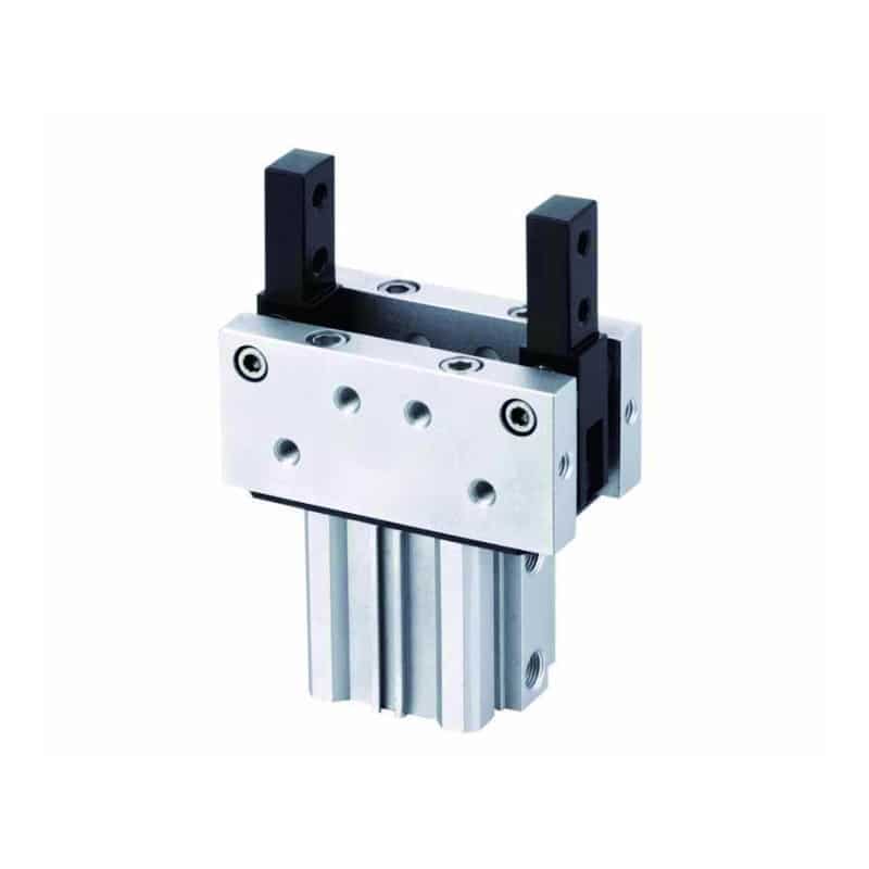
A toggle clamp converts cylinder thrust through a changing linkage angle. Its final workpiece force therefore depends on pressure, arm geometry, mechanism efficiency, contact position, and the manufacturer’s rating.
What Are the Seven Pneumatic Fixture Selection Factors?
One SMC compact power-clamp catalog states 1,100 N at 0.5 MPa for a 32 mm model with a 50 mm arm, while another configuration is rated at 200 N at 0.6 MPa (SMC Power Clamp Cylinder catalog, accessed 2026). That spread shows why fixture selection must preserve model, geometry, and test conditions.
The seven factors form one acceptance chain:
| Factor | Engineering question | Evidence required before release |
|---|---|---|
| 1. Required holding force | What load tries to lift, slide, or rotate the workpiece? | Free-body diagram, worst-case process load, approved margin |
| 2. Effective pressure | What pressure reaches the actuator during the real cycle? | Point-of-use minimum pressure and flow record |
| 3. Stroke and load path | Does the clamp seat the part without bending it? | Part tolerance stack, contact travel, support layout |
| 4. Loss-of-energy behavior | What happens when air or electrical power disappears? | Risk assessment, circuit state table, isolation method |
| 5. State verification | Can the controller distinguish open, clamped, and abnormal states? | Sensor windows, pressure limits, sequence logic |
| 6. Duty and environment | Will speed, temperature, chips, coolant, and maintenance access remain within limits? | Exact catalog limits and production trial |
| 7. Changeover interface | Can the fixture be exchanged without losing its reference or connecting the wrong services? | Interface drawing, repeatability test, poka-yoke checklist |
The factors are linked. Pressure cannot correct a poor support layout, a position switch cannot prove force, and a quick-change plate cannot overcome chips on its locating interface. Every gate needs an acceptance criterion and test method.
Factor 1: How Much Holding Force Does the Fixture Really Need?
Carr Lane’s worked example doubles a calculated 1,290 lbf requirement to 2,580 lbf, but presents the 2-to-1 margin as application guidance, not a universal rule (Carr Lane locating and clamping principles, accessed 2026). Margin depends on load uncertainty, slip consequence, and verification.
Start with a free-body diagram covering process force, acceleration, gravity, ejector force, hose reaction, and offset moments. Separate loads that seat the part from those that lift, slide, or rotate it.
Cylinder thrust is the actuator’s direct axial output before any external linkage:
Here, is cylinder thrust in newtons, is the measured pressure acting across the piston in pascals, is effective piston area in square metres, and is an allowance for seal friction and other cylinder losses. Use the manufacturer’s force data when available instead of inventing .
A linkage converts that thrust into contact force:
Here, is the mechanism ratio at linkage angle and arm geometry , while covers joint friction and compliance. The ratio changes through a toggle stroke, so cylinder force alone cannot certify final force. Fixture clamping force is the contact force delivered at the pad under the stated pressure, geometry, linkage angle, and friction condition.
Arm length also creates moment:
is the applied moment, is the force component acting at offset , and the result must remain within the clamp, pivot, mounting, and fixture ratings. SMC, for example, states a 75 N·m maximum holding moment for one CKZT variant after operating air is exhausted, then warns that this is not its permissible moment for normal use (SMC CKZT catalog, accessed 2026).
The most economical fix for an apparently weak clamp is often a better load path. Moving a support under the contact point or redirecting the process load into a solid locator can reduce the force the actuator must resist. The pneumatic cylinder force-factor guide covers the actuator side; the fixture drawing must still close the mechanical equilibrium.
Factor 2: What Pressure Reaches the Clamp During Production?
SMC lists a minimum operating pressure of 0.1 MPa and a maximum of 0.7 MPa for one C(L)KQG32 pin-clamp configuration, with different limits for its lock-equipped version (SMC C(L)KQG32 catalog, accessed 2026). Those boundaries demonstrate why header pressure is not an acceptable substitute for point-of-use data.
Measure pressure at the fixture during the most demanding cycle step. Record the lowest stable value with simultaneous demand, filter loading, regulator droop, tubing loss, and commanded flow. An idle gauge reading misses dynamic loss.
Check four pressure states:
- Normal production with every usual consumer active.
- The lowest supply condition the plant permits.
- Startup after an extended shutdown or line vent.
- The pressure present during simultaneous clamp movement.
Pressure margin should be evaluated against the exact clamp curve. DESTACO’s 82L-3E catalog plots different clamping forces at 3, 4, and 5 bar and states its headline data at 6 bar with a one-second opening or closing time (DESTACO 82L-3E catalog, accessed 2026). A force rating at 6 bar cannot be assumed at 4 bar.
Use the compressed-air pressure-drop calculator to screen tube length and flow before commissioning, then confirm the selected line, fittings, valve, and silencer on the machine. The related article on pressure fluctuations and actuator consistency explains why a regulator setting alone does not define available force.
Factor 3: Do Stroke, Tolerance, and Support Geometry Work Together?
The SMC C(L)KQG32 example combines a 12.5 mm cylinder stroke with a 10 mm clamp stroke and notes that clamping force may take about 0.3 seconds to develop after movement begins (SMC C(L)KQG32 catalog, accessed 2026). Fixture travel and force-building time are therefore separate acceptance variables.
Stack the thinnest and thickest workpieces with locator wear, pad wear, mounting tolerance, and expected debris. Confirm that every valid part reaches the rated clamping zone. A cylinder that bottoms before pad contact can signal position without holding force.
Carr Lane describes a 3-2-1 locating layout using six locators to establish the required reference while the clamp restricts the remaining direction (Carr Lane, accessed 2026). The exact layout varies, but the principle is stable: locators define position; supports prevent deflection; clamps maintain contact.
Place the clamp over a support or a structurally strong part feature. A clamp acting over an unsupported wall can bend the part while every sensor reports a successful cycle. The pad shape, material, and contact area should control marking and local pressure. SMC explicitly cautions that excessive clamping force can damage the workpiece, so greater force is not automatically safer.
A practical acceptance test uses three master conditions: the minimum-material workpiece, maximum-material workpiece, and a controlled contamination challenge at the locating interface. Record final position, pressure, cycle time, and part deformation for each. This reveals tolerance failures that a nominal sample cannot show.
Factor 4: What Happens When Air or Electrical Power Is Lost?
OSHA 29 CFR 1910.147 identifies pneumatic energy as hazardous energy and requires stored or residual energy to be relieved, disconnected, restrained, or otherwise made safe before covered servicing work (OSHA lockout/tagout application, accessed 2026). A directional valve’s center condition is not a substitute for an energy-control procedure.
Define the required state for each foreseeable event:
| Event | Required design question |
|---|---|
| Supply pressure falls slowly | At what pressure can the workpiece move or the clamp unlock? |
| Supply line ruptures | Does the load remain mechanically retained, move to a safe state, or require external support? |
| Solenoid power disappears | Which valve state results, and is that state safe for the process? |
| Emergency stop occurs | Must pressure be exhausted, retained, or divided by safety function? |
| Maintenance begins | How are supply and trapped pressure isolated and verified? |
| Restart occurs | Can the fixture move before the workpiece and guards are checked? |
A spring lock or over-centre toggle can retain a state, but its published holding value needs careful interpretation. The SMC CLK2 lock uses spring locking and lists lock holding as maximum static load; the CKZT example likewise distinguishes air-exhaust holding moment from normal permissible load. Neither rating proves that the complete fixture is safe for people.
Machine guarding remains separate. OSHA requires guarding for point-of-operation and nip hazards on pneumatic presses (OSHA pneumatic presses, accessed 2026). Where the clamp participates in a safety-related control function, validate the architecture using the machine risk assessment and applicable functional-safety standard. The ISO 13849 pneumatic safety-circuit guide provides the control-system context.
Factor 5: Can the Controller Verify the Actual Fixture State?
One SCHUNK pneumatic sensory clamping family reports jaw position and pressure from both chambers through IO-Link, while its quick-change module distinguishes open, clamped with a pin, and closed without a pin (SCHUNK sensory clamping blocks, accessed 2026). Those are three different states, not one generic “clamp complete” bit.
Select sensors around the failure you need to detect:
- Open position: confirms clearance for loading and tooling.
- Clamped position: confirms travel entered the validated window.
- Pressure: confirms the actuator received the minimum accepted pressure.
- Part present: prevents a clamp from completing on an empty station.
- Pallet present: distinguishes a real interface from a closed mechanism without tooling.
- Cycle timeout: detects slow travel, obstruction, flow restriction, or a missing signal.
Position plus pressure is stronger than either signal alone, but it still does not measure workpiece holding force unless the fixture includes a calibrated force sensor. Set sensor windows using minimum and maximum workpiece conditions, then fault the cycle when signals arrive in an impossible order.
Do not place a reed switch where its entire operating range overlaps both an acceptable and unacceptable mechanical condition. Record the switch position, hysteresis, mounting tolerance, and cable protection. For quick-change tooling, code or mechanically key the service connections so a correct position cannot be paired with the wrong pneumatic circuit.
Factor 6: Do Duty Cycle and Environment Stay Inside the Catalog Limits?
The SMC C(L)KQG32 example specifies 50 to 150 mm/s clamp speed and an ambient and fluid range of -10 to 60°C with no freezing (SMC C(L)KQG32 catalog, accessed 2026). These are model limits, not a general range for every pneumatic fixture.
Document cycles per hour, tooling mass, arm centre of gravity, opening angle, and motion time. Excessive arm weight or speed increases joint and stop loads even when static force is adequate. DESTACO warns that arm weight affects cycle life, so review custom arms against the exact series.
Environmental questions belong in the selection sheet:
- Can chips pack behind the clamp arm or on a locator?
- Does coolant attack seals, pads, cables, or coatings?
- Is washdown pressure aimed at a vent or bearing?
- Can condensate freeze at the minimum temperature?
- Is welding spatter present?
- Can maintenance reach the pivot, sensor, regulator, and manual release?
Use manufacturer inspection triggers, not an invented calendar. Track cycle count, contamination, speed, pressure, sensor drift, leakage, pad wear, and pivot play. For vibration, compare measured natural modes with the forcing spectrum; the natural-frequency guide covers that analysis.
Factor 7: Will Quick-Change Interfaces Preserve Location and Services?
SCHUNK publishes repeat accuracy below 0.005 mm, an 8 kN pull-down force, and 6 bar unlocking pressure for one NSE3 138 pneumatic module (SCHUNK NSE3 138, accessed 2026). Those figures describe that module and cannot be transferred to every zero-point or ball-lock system.
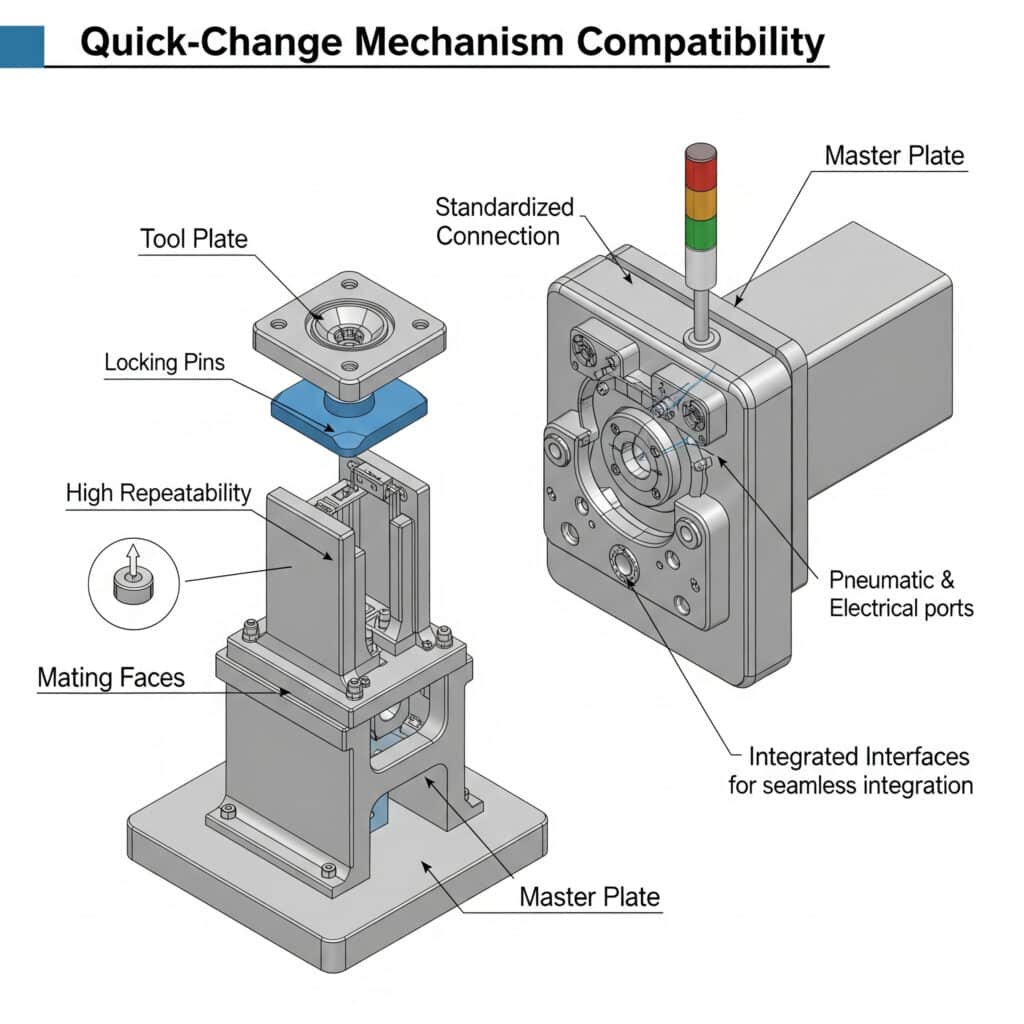
Quick-change acceptance must cover locating features, pull-down retention, pneumatic and electrical services, contamination control, and the method used to confirm the correct tooling is installed.
Check the complete interface rather than a brand name:
- Primary and secondary locating features.
- Pull-down or retention capacity under the worst overturning moment.
- Flatness, mounting torque, and base stiffness.
- Chip exclusion and cleaning method.
- Air, vacuum, electrical, and data connectors.
- Pallet identity and wrong-tool prevention.
- Repeatability after realistic contaminated changeovers.
Carr Lane states ±0.0005 inch clamping repeatability for its Carr Lock system, but one 16 x 20 plate page gives ±0.0028 inch resulting x-y repeatability after tolerance accumulation (Carr Lock fixture plate, accessed 2026). Fixture repeatability means the measured variation of the defined feature under stated installation, load, thermal, cleaning, and test conditions; it is not a component headline.
Qualify a quick-change fixture with a removal-and-reinstallation study, not repeated measurements without disturbing the plate. Include interface cleaning, service reconnection, operator variation, and thermal state. A gauge result taken after one careful laboratory installation does not represent production changeover.
How Should the Fixture Be Validated Before Release?
ISO 12100 covers hazard identification, risk estimation, risk evaluation, and risk reduction across machinery life-cycle phases (ISO 12100, 2010). Apply it alongside a written fixture acceptance test; a quotation or one successful dry cycle is not production evidence.
Use a controlled test sequence:
- Verify model codes, drawings, arm geometry, fasteners, pads, and service connections.
- Test minimum and maximum workpiece conditions.
- Apply the worst credible process load and offset.
- Run at minimum permitted production pressure.
- Run simultaneous pneumatic demand elsewhere on the machine.
- Record clamped position, point-of-use pressure, cycle time, and part deformation.
- Inject missing-part, obstruction, low-pressure, sensor, and power-loss faults.
- Remove and reinstall quick-change tooling through multiple realistic changeovers.
- Inspect the interface after chips, coolant, and the planned cleaning method.
- Approve limits, reaction logic, maintenance triggers, and isolation instructions.
Stop acceptance at a failed test and identify the controlling boundary. For low force, isolate pressure, actuator area, arm geometry, and friction. For position variation, separate workpiece tolerance, contamination, compliance, and sensor-window error.
For purchasing, place those boundaries in the RFQ. The custom pneumatic-cylinder RFQ guide lists the load, pressure, stroke, environment, mounting, sensing, and documentation inputs a supplier needs. If the plant is reducing spare variants, connect the fixture decision to the cylinder standardization strategy without forcing one model into incompatible applications.
Siyu Wang prepared this application-selection guide for Bepto Pneumatic. For a fixture review, provide the process-force estimate, workpiece tolerance range, locator and support drawing, minimum point-of-use pressure, cycle target, environmental exposure, required loss-of-energy state, and acceptance-test limits through the contact page.
Pneumatic Fixture Selection FAQs
SMC publishes a 10 mm clamp stroke, 50 to 150 mm/s speed range, and 0.1 MPa minimum pressure for one C(L)KQG32 configuration (SMC, accessed 2026). These three values answer different questions, which is why fixture selection cannot be reduced to bore size or nominal clamping force.
Can cylinder force be used as pneumatic fixture clamping force?
Not directly. Cylinder force is pressure multiplied by effective piston area, with friction allowance. A toggle, cam, wedge, or linkage changes that force according to angle, arm length, joint losses, and contact position. Use the manufacturer’s clamping-force curve for the exact mechanism and verify the complete fixture under its worst load.
Should a clamp hold the workpiece if air pressure is lost?
Only when the machine risk assessment requires that behavior and the selected mechanism is rated for it. A spring lock or over-centre toggle may retain a static state, but catalog holding load is not automatically a personnel-safety rating. Define guarding, isolation, trapped-energy release, restart behavior, and load support separately.
Does a clamped-position switch prove adequate holding force?
No. A position switch confirms that a target entered its sensing window. Pair position with minimum pressure, part presence, sequence timing, and fault logic. Even that combination infers rather than measures force. Validate holding capacity during commissioning with the accepted workpiece extremes, process load, point-of-use pressure, and mechanism geometry.
How should pneumatic fixture repeatability be specified?
Specify the measured feature, coordinate directions, datum, load state, temperature, number of removal-and-reinstallation cycles, cleaning method, instrument uncertainty, and acceptance limit. A component’s published repeatability does not include fixture-plate tolerance, mounting error, workpiece location, contamination, or sensor variation unless its test definition explicitly includes them.
What information belongs in a pneumatic fixture RFQ?
Include process-force magnitude and direction, workpiece drawings and tolerance range, locator and support scheme, required clamp stroke, minimum dynamic pressure, cycle time, environment, arm geometry, loss-of-energy state, guarding assumptions, sensors, service interfaces, quick-change requirements, maintenance access, documentation, and the production acceptance test.
Sources and technical references
- ISO 4414:2010, Pneumatic fluid power - General rules and safety requirements for systems and their components. System design, installation, operation, maintenance, reliability, energy, and environmental scope. Accessed July 27, 2026. https://www.iso.org/standard/44790.html
- ISO 12100:2010, Safety of machinery - General principles for design - Risk assessment and risk reduction. Machinery risk-assessment and risk-reduction methodology. Accessed July 27, 2026. https://www.iso.org/standard/51528.html
- OSHA 29 CFR 1910.147 and lockout/tagout application guidance. Control of pneumatic and other hazardous energy during servicing. Accessed July 27, 2026. https://www.osha.gov/laws-regs/regulations/standardnumber/1910/1910.147
- OSHA Machine Guarding eTool, Pneumatic Presses. Point-of-operation and nip-hazard guarding. Accessed July 27, 2026. https://www.osha.gov/etools/machine-guarding/presses/pneumatic
- SMC Power Clamp Cylinder catalogs. Model-specific clamping force, pressure, stroke, timing, holding, sensor, speed, and environmental limits. Accessed July 27, 2026. https://www.smcworld.com/catalog/PowerClamp-en/pdf/PowerClamp-Common_en.pdf
- DESTACO 82L-3E Enclosed Pneumatic Power Clamps catalog. Pressure, arm-length, timing, tooling-weight, and air-consumption relationships. Accessed July 27, 2026.
- Carr Lane Locating and Clamping Principles. Load paths, supports, locators, clamp placement, workpiece protection, and force calculations. Accessed July 27, 2026. https://www.carrlane.com/engineering-resources/fixture-design-principles/locating-clamping-principles/ctl
- SCHUNK NSE3 138. Model-specific pull-down force, unlocking pressure, and repeat accuracy. Accessed July 27, 2026. https://schunk.com/us/en/workpiece-clamping-technology/quick-change-pallet-systems/quick-change-pallet-system-for-general-milling-applications-and-heavy-duty-cutting/individual-modules-nse3/nse3-138/p/000000000001313721