

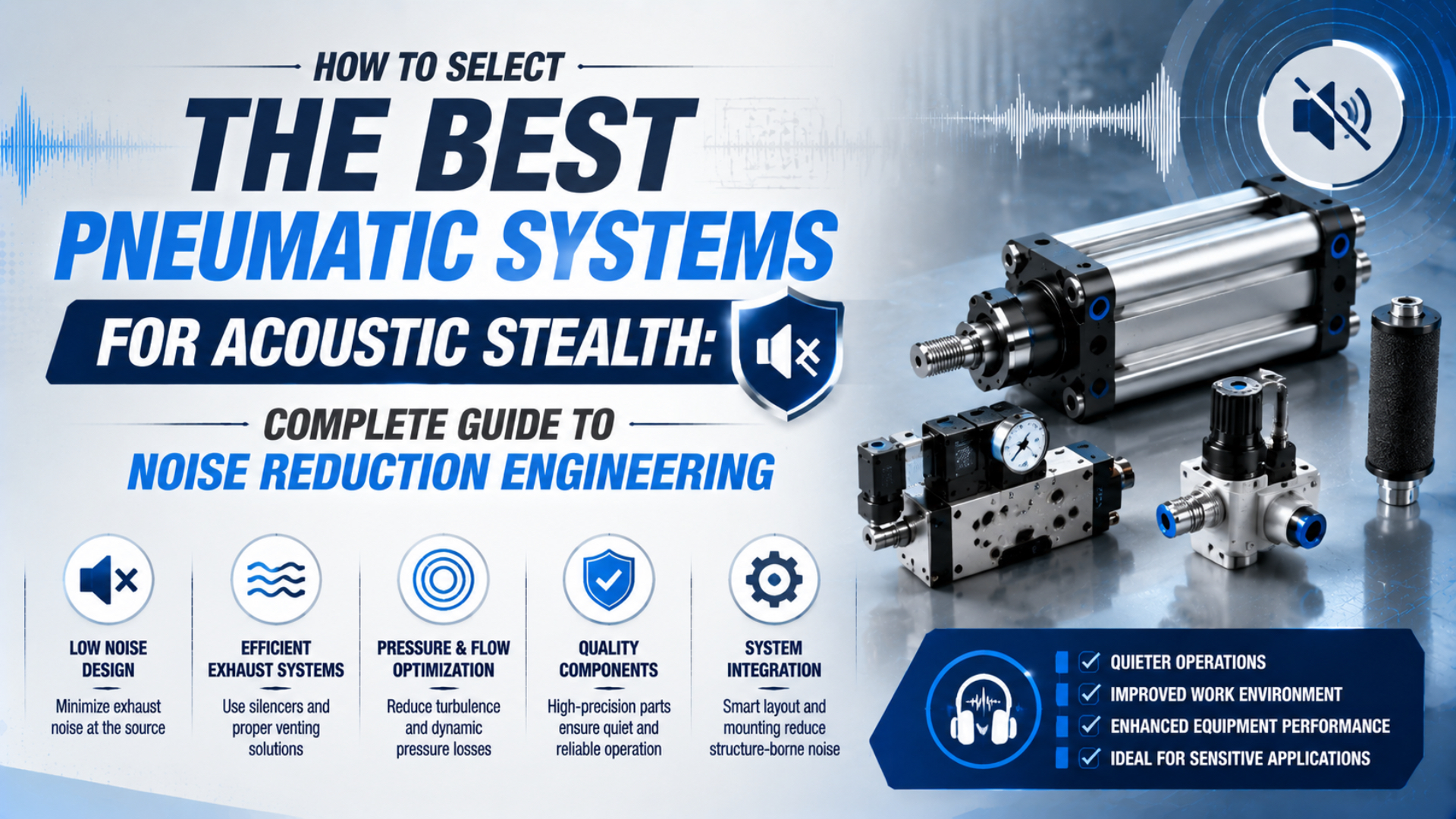
The best low-noise pneumatic system is selected as a complete source, path, and receiver problem. Start with a measurable acoustic requirement, then choose the actuator, valve, tubing, exhaust treatment, pressure setting, mounting, and controls that meet it without losing force, cycle time, repeatability, or machine safety.
In this guide, acoustic stealth means making pneumatic operation unobtrusive in noise-sensitive industrial settings. Examples include laboratories, medical equipment, electronics inspection, recording and test rooms, and production areas that run near occupied spaces. It does not mean military concealment or avoiding detection systems.
No component is quiet in isolation. A valve’s catalog figure, a silencer’s stated attenuation, or a phone reading beside the machine cannot predict the sound at an operator position. The installation, operating event, measurement method, background, and nearby surfaces remain part of the result.
Key Takeaways
- OSHA’s hearing-conservation action level is an 85 dBA 8-hour TWA, not a component noise limit.
- Separate exhaust, impact, leakage, valve actuation, and structure-borne sound before selecting controls.
- Specify the acoustic quantity, operating cycle, microphone position, force, stroke time, and allowable back pressure.
- Verify the assembled machine, not just individual parts.
The video explains supply, work, and exhaust paths. Those paths must be identified before a low-noise design can assign silencers, remote exhaust lines, or flow controls to the correct ports.
What Does Acoustic Stealth Mean in an Industrial Pneumatic System?
NIOSH reports that even a 3 dB reduction in worker noise exposure can reduce hearing-loss risk, while ISO/TR 11688-1 treats low-noise design as a task that can begin at any machinery design stage. Industrial acoustic stealth therefore means a verified reduction at the position and operating condition that matter. (NIOSH; ISO/TR 11688-1)
The term should be translated into one of three measurable objectives:
| Objective | Useful acoustic quantity | What must be stated |
|---|---|---|
| Protect workers | Personal dose or task-based TWA | Shift duration, production mix, worker movement, other sources |
| Compare machines | Emission sound pressure or sound power | Test method, mounting, operating cycle, background, microphone geometry |
| Protect a sensitive process | Level or spectrum at a defined receiver | Receiver position, frequency range, allowable transient, ambient baseline |
A laboratory may care about a short valve click during a measurement window. A night-shift packaging line may care about the level at a neighboring occupied room. A medical device may need quiet motion near a patient while still meeting hygiene, response, and fail-safe requirements. These are different specifications.
Avoid requirements such as “silent,” “inaudible,” or “stealth grade.” They don’t identify a measurement method or acceptance condition. A useful requirement names the operating event, sound quantity, weighting, time response, microphone position, background treatment, and maximum permitted result.
How Should You Define a Noise Requirement Before Selecting Components?
OSHA’s general-industry hearing-conservation action level is an 8-hour TWA of 85 dBA, while Table G-16 lists 90 dBA for 8 hours. ISO 11202 can determine emission sound pressure at workstations or other defined positions. Neither framework turns one catalog dB value into proof that the assembled machine is acceptable. (OSHA 1910.95; ISO 11202)
Write the acoustic requirement alongside the motion requirement:
- machine state and event to be tested;
- working pressure, load, stroke, speed, dwell, and cycle rate;
- number of valves or actuators operating simultaneously;
- microphone or receiver position and orientation;
- A-weighting, C-weighting, unweighted spectrum, or other requested quantity;
- time response, averaging interval, and background correction;
- maximum sound result or required improvement;
- minimum force, maximum stroke time, repeatability, and settling time;
- permitted exhaust back pressure and residual pressure;
- required safety state and maximum pressure-decay time.
Sound pressure at an operator position and sound power from a defined test surface are not interchangeable. ISO 3744:2025 provides an engineering method for determining sound power from an enveloping measurement surface. ISO 11202 addresses emission sound pressure near the machine. Worker exposure requires a separate representative exposure assessment.
Can a supplier still quote a quiet product before the final machine exists? Yes, but the quotation must state the test method and operating point. The machine builder then owns installed verification because guards, frames, tubing, exhaust routing, and the room can change the result.
Where Are the Noise Source, Propagation Path, and Receiver?
OSHA describes pneumatic valves, cylinders, solenoids, and compressed-air nozzles as common manufacturing noise sources. NIOSH separates source reduction from controls along the propagation path and at the receiver. A useful acoustic map therefore identifies each event, how it reaches the receiver, and what secondary machine requirement a proposed control might disturb. (OSHA Technical Manual; NIOSH)
Start with the machine sequence. Mark valve energization, actuator start, cushion entry, mechanical contact, exhaust release, and leak checks on the same timeline. A short hiss, click, ring, and impact can occur within a fraction of one cycle yet require different remedies.
Common diagnostic splits include:
- Short broadband burst: valve or quick-exhaust discharge.
- Sharp click: solenoid armature, spool, relay, or hard stop.
- Low-frequency ring: guard, panel, manifold, or frame radiation.
- Repeating impact: uncontrolled actuator or tooling deceleration.
- Continuous hiss: external leakage, internal leakage to exhaust, or a service nozzle.
- Whistle or tone: a restriction, gap, cavity, tube, or regulator interaction.
The pneumatic valve acoustic-signature guide covers synchronized pressure, sound, and vibration diagnosis in greater depth. Keep this system-selection review focused on which hardware and acceptance data belong in the design.
How Do You Select an Actuator and Motion Profile for Less Impact Noise?
NIOSH recommends reducing the speed of moving parts and shortening drop distance to lower impact noise. Pneumatic actuator selection should therefore control moving mass, free travel, contact velocity, cushioning, and mount stiffness while still meeting force and cycle time. A quieter exhaust cannot compensate for a carriage or tool striking a hard stop. (NIOSH engineering controls)
Select bore from the required force and available effective pressure, not from noise alone. An unnecessarily large bore increases chamber volume and displaced air. An undersized bore may force a higher pressure or cause unstable motion near its load limit. Both choices can worsen the final acoustic result.
The motion profile matters just as much:
| Design variable | Lower-noise direction | Check before acceptance |
|---|---|---|
| Moving mass | Remove unnecessary tooling and adapter mass | Strength, stiffness, center of mass |
| Free travel | Minimize travel before contact where the process allows | Access, part variation, sensor position |
| Speed | Use only the speed needed for takt time | Throughput and control stability |
| End cushioning | Decelerate before the mechanical stop | Cushion capacity and rebound |
| External shock absorber | Use when actuator cushioning cannot absorb the energy | Energy per cycle, temperature, mounting |
| Guidance and alignment | Prevent side load, rattle, and carriage binding | Load moments and mounting tolerances |
A long-stroke rodless cylinder may avoid the external rod space of a conventional cylinder, but it still needs correct guidance, mount alignment, and end-of-stroke energy control. The guide to actuator mounting and alignment explains how external load paths affect wear and vibration.
If a narrow tone or frame vibration appears, compare the forcing rate with structural resonance instead of adding random rubber pads. The natural-frequency calculation guide provides the next diagnostic step.
How Do You Select Valves and Tubing Without Creating Turbulence?
NIOSH states that restricted flow and abrupt obstructions in pipes or ducts can increase turbulence and noise, while smoother transitions tend to be quieter. A low-noise pneumatic valve circuit should provide the required conductance without unnecessary local restrictions, unstable pilot pressure, tube whip, or a high-flow exhaust aimed at a reflective panel. (NIOSH engineering controls)
Choose the valve using function and operating point first:
- valve function and safe state;
- required flow characteristic at the real pressure ratio;
- response and repeatability needed by the sequence;
- pilot-pressure and electrical-drive limits;
- exhaust-port arrangement and allowed accessories;
- permitted leakage, temperature, air quality, and service life;
- mounting method and mechanical isolation from radiating panels.
An oversized valve is not automatically quieter. It may discharge a chamber more abruptly, while an undersized valve can create a dominant throttling restriction and longer flow event. The correct size is the one that meets motion time at the lowest practical pressure and remains stable with the actual tubing, fittings, flow controls, and exhaust hardware.
Keep tubing routes short enough for response, but don’t create tight bends, crushed sections, unsupported spans, or hard contact with sheet metal. Clamp lines so pressure pulses cannot make them strike a guard. When a fitting or reducer becomes the smallest passage, its internal geometry can control both performance and sound. See the fitting-selection efficiency guide for passage and pressure-loss checks.
How Can You Control Exhaust Noise Without Sacrificing Cycle Time?
OSHA’s technical manual says diffuser-type pneumatic silencers can provide 15 to 30 dB of noise reduction, but it also warns that unacceptable back pressure and plugging can defeat the control. Treat that range as general retrofit guidance, not a guarantee for a specific valve, cycle, or installed microphone position. (OSHA Technical Manual)
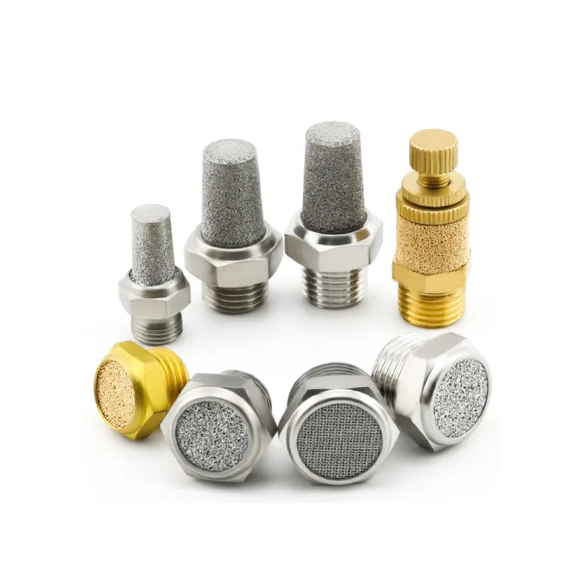
Pneumatic silencers come in different flow paths and adjustment styles. Thread size alone does not establish acoustic performance or back pressure.
For ordinary valve and actuator exhaust:
- Identify the active exhaust port for each direction.
- Estimate the chamber flow required by the target motion.
- Select a silencer from model-specific flow and pressure-loss data.
- Direct the outlet away from receivers, debris, and sensitive equipment.
- Test sound, stroke time, cushioning, and residual pressure.
- Define an inspection trigger for damage, contamination, and restriction.
Manufacturer data illustrates why conditions matter. SMC lists a 30 dB(A) noise-reduction effect for its AN series under stated conditions, while Festo UC data reports model-dependent sound-pressure values of 60 to 68 dB(A) at 6 bar and 1 m. Neither value predicts the assembled machine. (SMC AN; Festo UC)
The pneumatic muffler guide covers silencer construction, flow sizing, clogging, and replacement. If the required exhaust flow is unclear, use the Cylinder Flow Requirement Calculator as an early estimate, then confirm the valve and silencer data at the real operating point.
Cleaning and blow-off nozzles are a different problem. They intentionally direct air toward a task and must meet their own pressure, chip-guarding, and personal-protection requirements. The guide to pneumatic exhaust discharge safety separates cleaning nozzles, fixed exhaust, quick exhaust, and safety dump paths.
Reduce Structure-Borne Noise Through Mounting and Layout
NIOSH warns that incorrectly selected vibration mounts can increase vibration, even though suitable isolation can reduce structure-borne noise. It also notes that rigid pipe connections and large attached panels can transmit and radiate sound. Mount selection therefore requires supported mass, forcing frequency, stiffness, damping, motion limits, and alignment data. (NIOSH engineering controls)
Start with mechanical condition. Tighten loose guards, repair worn guides, correct cylinder alignment, support tubing, and prevent manifolds or valve islands from exciting thin sheet metal. Adding isolation beneath a defective assembly only changes the way the fault reaches the frame.
Then evaluate the transmission path:
- mount valve manifolds on a stiff, non-ringing support;
- avoid placing exhaust outlets directly beside large reflective panels;
- use approved flexible connections where rigid tube transfers vibration;
- isolate guards or enclosures without weakening machine safety;
- add damping to a verified radiating panel, not every available surface;
- keep service openings small and seal acoustic leaks where enclosure design permits;
- place absorptive treatment on the source side of barriers.
Enclosures can reduce airborne sound, but they also affect access, heat, contamination, visibility, and emergency release. A sealed box around a pneumatic assembly may trap heat or redirect exhaust. Include ventilation silencers, safe exhaust routing, and maintenance access in the enclosure design rather than treating them as later penetrations.
What if isolation makes motion less accurate? Stop and revise the mount. A low-noise system still has to carry reaction forces and preserve sensor, tooling, and actuator alignment. Record position repeatability and settling time during the same before-and-after test used for sound.
Apply the Noise-Control Hierarchy in the Right Order
NIOSH places elimination and substitution above engineering controls, administrative controls, and personal protective equipment. It also states that a 3 dB exposure reduction can lower hearing-loss risk. For pneumatic machinery, this hierarchy favors removing unnecessary air use and impact energy before adding silencers, enclosures, schedules, or hearing protectors. (NIOSH; NIOSH engineering controls)
This order prevents a common mistake: installing an elaborate enclosure around a system that still leaks, slams, or operates at unnecessary pressure. Repair and simplify first. The remaining engineering controls will be smaller, easier to maintain, and less likely to impair pneumatic performance.
Active noise cancellation belongs at the specialist end of the process, not the beginning. Consider it only after the dominant source and path are measured, the sound is sufficiently repeatable for the proposed control, and passive source controls cannot meet the requirement. Require a prototype test at all receiver positions because cancellation at one point can change the field elsewhere.
Validate the Installed System Under Real Operating Conditions
ISO 11202 produces grade 2 or grade 3 emission sound-pressure results at specified positions when its requirements are met. OSHA requires representative monitoring when information indicates employee exposure may reach the 85 dBA action level. Validation must therefore reproduce the real pressure, load, cycle mix, accessories, guards, background, and receiver position. (ISO 11202; OSHA 1910.95)
Use a matched before-and-after test:
- Mark the microphone position from a repeatable machine datum.
- Record weighting, detector response, averaging interval, and calibration.
- Record pressure, load, temperature, cycle rate, and operating sequence.
- Synchronize sound with valve command and actuator position.
- Measure extend and retract time, not only total cycle time.
- Check exhaust back pressure and pressure decay where relevant.
- Confirm force, repeatability, cushioning, settling, and safe motion.
- Repeat enough cycles to capture normal variation.
- Repeat at other defined receivers if people or sensitive processes move.
| Acceptance channel | Why it belongs in the same test |
|---|---|
| Sound at defined receiver | Proves the acoustic target under the specified method |
| Employee dose or TWA | Addresses occupational exposure rather than component emission |
| Stroke and cycle time | Detects restriction from silencers, tubing, or flow controls |
| Dynamic chamber pressure | Shows fill, exhaust, and residual-pressure behavior |
| Force or grip margin | Prevents pressure reduction from weakening the task |
| Position and settling | Detects soft mounts, rebound, or unstable motion |
| Safety-function response | Confirms noise controls did not delay the safe state |
The article on pneumatic gripper noise and vibration shows how to separate exhaust, impact, force, and workplace exposure at a complete station.
What Should a Low-Noise Pneumatic RFQ Include?
ISO/TR 11688-1 supports controlling machinery noise during planning, while OSHA uses 85 dBA as the 8-hour hearing-conservation action level. A useful RFQ must therefore translate “quiet” into a testable acoustic result and provide enough pneumatic data to prevent the supplier from meeting it by sacrificing flow, force, or safe-state time. (ISO/TR 11688-1; OSHA 1910.95)
Send the supplier or integrator:
- application description and why the receiver is noise-sensitive;
- actuator type, bore, stroke, load, mounting, orientation, and moving mass;
- required force, speed, acceleration, deceleration, repeatability, and cycle rate;
- valve function, safe state, voltage, response requirement, and manifold layout;
- working pressure range, air quality, temperature, and expected simultaneous demand;
- tubing material, inside diameter, length, fittings, and permitted routing;
- exhaust arrangement, silencer requirement, allowable back pressure, and contamination;
- acoustic quantity, limit, frequency range, time response, and measurement method;
- microphone or receiver location, background condition, and machine operating state;
- guard, enclosure, cleanability, heat, access, and maintenance constraints;
- required acceptance tests and evidence format;
- change-control rules for alternate valves, silencers, tubing, and mounts.
Ask for model-specific conditions behind every acoustic claim. “20 dB quieter” is incomplete without the baseline, pressure, flow, duty, load, distance, installation, weighting, and measurement method. A supplier can still provide useful preliminary data, but the purchase specification should reserve final acceptance for the assembled machine.
Acoustic Stealth Pneumatic System FAQs
OSHA’s 85 dBA action level applies to an 8-hour employee exposure average, while ISO 11202 measures machinery emission at defined positions. These two references answer different questions, so the FAQ below keeps component selection, installed acoustic performance, worker exposure, and pneumatic validation separate. (OSHA 1910.95; ISO 11202)
Is 85 dBA the maximum allowed noise for a pneumatic component?
No. OSHA uses 85 dBA as the 8-hour TWA action level for a hearing-conservation program, not as a universal component limit. A valve or cylinder needs a declared emission test method, while compliance depends on representative employee exposure, duration, repetition, other sources, and the applicable workplace requirements.
Does lower pressure always make a pneumatic system quieter?
Lower pressure can reduce available flow energy and impact force, but it may also reduce actuator force or make motion unstable. Set the lowest pressure that still meets load and control requirements, then measure the result. Pressure alone cannot predict installed dBA because geometry, flow, duration, mounting, and the room also matter.
Can a silencer make a pneumatic cylinder slower?
Yes. An undersized, contaminated, or over-adjusted silencer can create exhaust back pressure and increase stroke time. Select it from model-specific flow data, then test both motion directions with the final valve, tubing, pressure, load, and cycle rate. Include maintenance condition when a safety function depends on pressure decay.
Is active noise cancellation practical for pneumatic machinery?
Sometimes, but it is rarely the first control. Active cancellation needs a measured, repeatable source and a defined receiver region. Pneumatic exhaust and mechanical impacts can vary from cycle to cycle. Repair leaks, reduce pressure and impact, improve exhaust treatment, and control vibration paths before commissioning a specialist active-control prototype.
How should suppliers prove low-noise pneumatic performance?
Require the supplier to state the sound quantity, operating point, mounting, accessories, microphone geometry, weighting, time response, and test method. Final acceptance should repeat the real machine cycle and check sound together with force, stroke time, back pressure, repeatability, residual pressure, and safety-function response.
Sources and technical references
All technical requirements and numeric examples are linked inline to ISO, OSHA, NIOSH, SMC, and Festo source pages so their scope and test conditions remain visible beside the claim.