

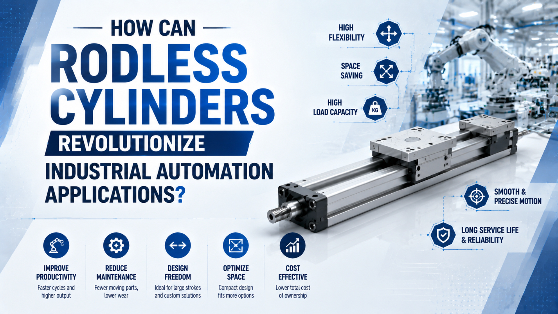
Rodless cylinders in industrial automation can change a machine layout when a long point-to-point stroke must fit inside a short envelope. They do not create precision, cleanliness, load guidance, or collaborative safety by themselves. The application works only when the coupling, guide, controls, stopping method, and environment match the complete motion requirement. That distinction matters in flexible-display, semiconductor, SMT, CNC, and cobot projects. Some axes are good pneumatic transfers. Others need an electric slider, linear motor, or servo-pneumatic package. Treat the industry name as context, then make the actuator decision from measurable requirements.
Key Takeaways
- Parker lists OSP-P strokes up to 6,000 mm for point-to-point and transfer duties.
- Clean magnetic cylinders still need separate load guidance and vacuum routing.
- Programmable precision or collaborative safety requires system-level controls, not a cylinder claim.
What Can Rodless Cylinders Actually Change in Industrial Automation?
Parker lists eight OSP-P bore sizes from 10 to 80 mm, a maximum standard stroke of 6,000 mm, and applications based on point-to-point, reciprocating, and simple traverse motion (Parker OSP-P, accessed 2026-07-27). Rodless cylinders change packaging and load placement, not the underlying control requirement.
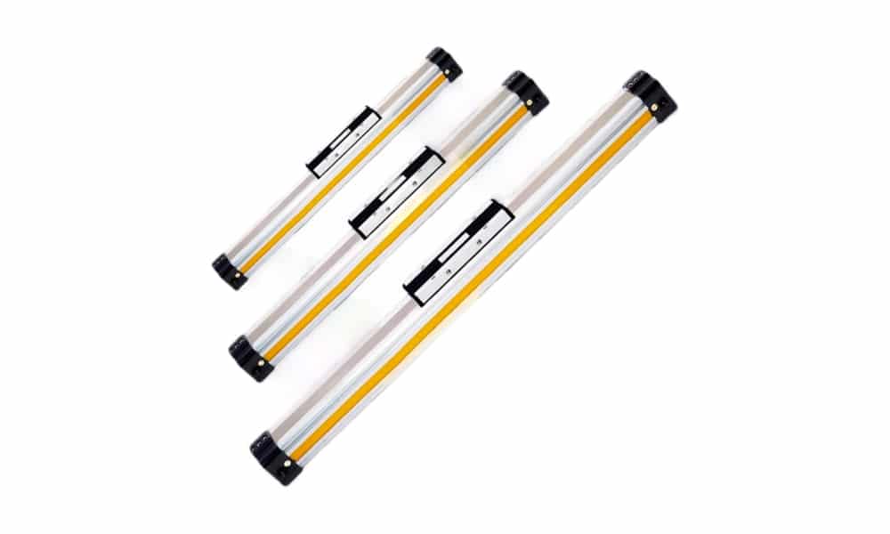
A rodless cylinder is a linear actuator that transfers piston motion to an external carriage without an exposed piston rod extending through the machine envelope. The coupling may be mechanical, magnetic, or cable based, and the load may require an integrated or separate guide. A conventional cylinder needs clearance for its body and extending rod. A rodless design moves the load on a carriage beside the cylinder profile, so the actuator can stay inside a machine frame, below a conveyor, or behind a guard. This benefit grows with stroke length.
The carriage also changes the load path. Tooling mounted above or beside it creates pitch, roll, and yaw moments. A basic cylinder may need a separate linear guide, while a guided model combines the drive and support functions. The catalog’s allowable moments, load-center offsets, speed, and combined-load method control that decision. Rodless is therefore a geometry choice first. It is not automatic proof of higher precision, longer life, or lower maintenance. The guide on rodless-cylinder types and coupling methods explains why magnetic, mechanical-joint, cable, and guided versions behave differently.
The useful question is not “Which industries use rodless cylinders?” Ask which machine constraint the carriage solves. If a long stroke, tight envelope, or moving load interface is the dominant problem, rodless deserves evaluation. If programmable position is dominant, start with the control architecture instead.
How Should Engineers Screen Five Advanced Automation Applications?
Parker publishes OSP-P force values up to 3,010 N at 6 bar and a maximum operating pressure of 8 bar, but it also makes the user responsible for analyzing every application condition (Parker OSP-P, accessed 2026-07-27). A five-stage screen prevents one catalog number from becoming a universal approval.
Start with the motion:
- Position pattern: two end positions, several indexed stops, or continuous closed-loop positioning.
- Load path: moving mass, load-center offsets, external forces, orientation, and guide arrangement.
- Dynamic demand: travel time, acceleration, deceleration, cushion energy, impact, and cycle rate.
- Environment: particles, washdown, vacuum exposure, temperature, magnetic debris, and cleanroom qualification.
- Failure state: loss of pressure, loss of power, coupling separation, blocked travel, and safe access.
A pneumatic rodless cylinder is strongest when the answer is two-position motion, manageable load moments, controlled end-of-stroke energy, and a defined response to air loss. Multi-position and tight path control shift the decision toward servo-pneumatic or electric motion.
Where Do Rodless Cylinders Fit in Flexible-Display Production?
SMC lists high-precision LEFS electric sliders at ±0.015 mm repeatability for step-motor versions and ±0.01 mm for AC-servo versions (SMC LEFS, accessed 2026-07-27). Those model-specific electric values show why a pneumatic rodless cylinder should not inherit an unsupported precision claim.
Rodless pneumatic cylinders can handle auxiliary transfer tasks around a display process: opening a cover, moving a fixture between hard stops, presenting a tray, shifting a web guide assembly, or retracting tooling. The best cases use external guidance and qualify the completed machine for vibration, settling time, and product contact. They are a weaker choice for active alignment, overlay correction, scanning, focus control, or any axis that needs many programmable positions. In those jobs, the actuator must control position between endpoints and often coordinate with machine vision. A ball-screw electric slider, linear motor, or another closed-loop axis is usually easier to specify.
Do not describe a magnetic cylinder as vibration-free. Pressure variation, compressible air, valve flow, hose volume, guide friction, load flexibility, and end cushioning all influence motion. If fragile material is involved, measure the actual acceleration and settling response at the tooling, not only the carriage speed.
The article on overshoot and settling in pneumatic slides provides the right dynamic checks for a stop-to-stop pneumatic axis.
When Is a Rodless Cylinder Suitable for Semiconductor Wafer Handling?
SMC’s 12-CY3 clean magnetically coupled family has nine listed bores from 6 to 63 mm, and the current catalog classifies both basic and direct-mount versions as guide non-integrated (SMC 12-CY3, accessed 2026-07-27). Clean construction and load guidance remain separate decisions.
A clean motion axis is the complete installed mechanism whose cylinder, guide, fittings, tubing, sensors, cables, lubrication, cleaning method, and maintenance practice collectively meet the applicable particle requirement. A clean-series actuator is only one part of that evidence.
A clean magnetic rodless cylinder can move a wafer cassette, cover, shield, tray, or transfer fixture when the motion is simple and the installed particle requirement is satisfied. Its closed tube avoids the longitudinal slot used by a mechanically jointed design, but the carriage, external guide, sensors, fittings, tubing, and lubricants still belong to the contamination assessment. The cylinder does not automatically include vacuum channels, multiple vacuum zones, a venturi generator, or leak detection. Those functions require their own documented manifold, tubing, ejector, sensor, and safe-release design. Route moving vacuum lines with a managed cable carrier or use a purpose-built transfer stage whose fluid passages are specified by the manufacturer.
Cleanroom suitability also cannot be inferred from the word “magnetic.” Record the exact clean-series code, test condition, permitted lubricant, mounting orientation, particle-generation evidence, cleaning method, and external guide. Then qualify the assembled mechanism in its actual operating zone.
For selection boundaries, see the guide to pneumatic components for Class 100 cleanroom applications.
In clean automation, the actuator is only one particle source. A clean cylinder paired with an unsuitable guide, cable carrier, fitting, or maintenance practice does not create a clean axis. Qualify the motion assembly, not the cylinder label in isolation.
Why Are Electric Axes Usually Better for the Primary SMT Z-Axis?
SMC’s AC-servo LEFS electric slider lists positioning repeatability of ±0.01 mm and acceleration or deceleration up to 20,000 mm/s² for specified configurations (SMC LEFS, accessed 2026-07-27). Pneumatic rodless cylinders do not provide those programmable positioning characteristics by default.
The primary placement Z-axis normally needs controlled approach, placement height, acceleration, deceleration, repeatable position, and synchronization with vision and feeder timing. An electric slider, voice-coil stage, linear motor, or another feedback-controlled axis is a better architectural starting point. Pneumatic rodless cylinders can still support SMT equipment. Useful tasks include feeder-bank access, cover motion, board-buffer transfer, reject routing, maintenance positioning, and fixture movement between mechanical stops. Those jobs benefit from compact travel without asking the cylinder to perform the placement head’s precision function.
Repeatability and accuracy are not interchangeable specifications.
Repeatability describes how closely an axis returns to commanded positions under stated conditions. Accuracy also includes calibration, structural errors, thermal effects, control resolution, load changes, and reference alignment. Never transfer a catalog repeatability value from an electric actuator to a pneumatic cylinder or to the entire machine.
CNC Tool-Changer Motion Needs Model-Specific Dynamic Checks
Parker states that OSP-P service intervals can reach 8,000 km and describes the series for point-to-point, reciprocating, and simple traverse applications (Parker OSP-P, accessed 2026-07-27). That product-specific distance is useful evidence, but it does not establish a universal cycle count or tool-change time.
A rodless cylinder can suit a tool-magazine shuttle, guard, cover, transfer arm, or auxiliary positioning slide when the load path is guided and the stops are controlled.
The cylinder should not be selected from bore and nominal speed alone.
Record the tool mass, fixture mass, carriage mass, center-of-gravity offsets, orientation, required travel time, approach speed, cycle rate, operating pressure during motion, valve and tubing data, cushion or shock-absorber selection, and jam condition. Compare them with the exact guide, cylinder, and stopping-device catalogs.
High acceleration can create a larger design problem than steady travel speed. The carriage guide must absorb moments, while the cushion or absorber handles kinetic energy at the stop. A larger bore can raise available force and impact energy without fixing an undersized guide or restricted exhaust path. Use the cylinder cushion energy guide and the article on inertia matching during high-mass deceleration for those separate checks.
In our experience reviewing tool-changer applications, the most useful evidence is a timed motion trace paired with load geometry. Our team found that this combination exposes whether the real constraint is valve flow, guide moment, impact energy, structural deflection, or a mechanical jam. From our work on these reviews, a maximum-speed catalog line rarely answers that question alone.
Can a Rodless Cylinder Be Used Safely in a Cobot Application?
ISO 10218-2:2025 is a 223-page integration standard covering industrial robot applications and cells through design, commissioning, operation, maintenance, and decommissioning (ISO 10218-2:2025, accessed 2026-07-27). A rodless cylinder can be one component in that system, but it is not a collaborative-safety function by itself.
A collaborative robot application is the integrated robot, end effector, workpiece, auxiliary equipment, safeguards, controls, operating task, and validated safety functions. Calling one auxiliary actuator collaborative does not establish the safety of that application. A guided rodless cylinder may move a fixture, tool tray, inspection device, or auxiliary slide near a robot. It may also extend an end-effector mechanism if the load, hose routing, pressure-loss state, and guarding strategy are engineered for that use.
Do not describe adjustable cushioning, low carriage inertia, or position switches as proof of human-safe motion. Collaborative operation depends on the complete application: robot, end effector, workpiece, auxiliary axes, controls, safety functions, layout, foreseeable misuse, validation, and task-specific risk assessment. Pressure loss needs special attention. A vertical pneumatic axis may fall or drift unless a suitable lock, brake, counterbalance, mechanical restraint, or safe supporting arrangement is provided. A directional valve’s center condition alone is not a reliable personnel-protection measure because leakage and hose failure remain possible.
The guide to holding a cylinder with a 5-way, 3-position valve explains why valve state and verified load holding are not the same requirement.
Choosing Pneumatic, Servo-Pneumatic, or Electric Motion
Parker lists OSP-P strokes up to 6,000 mm, while SMC lists ±0.01 mm repeatability for specified high-precision AC-servo LEFS sliders (Parker OSP-P; SMC LEFS, accessed 2026-07-27). These values describe different products and expose the central tradeoff between long compact transfer and programmable precision.
| Application | Pneumatic rodless fit | Better alternative when | Evidence required |
|---|---|---|---|
| Flexible display | Auxiliary two-position transfer with external guidance | Alignment, scanning, or tight settling controls quality | Tooling acceleration, settling trace, guide moments |
| Wafer handling | Qualified clean transfer with separate guide and vacuum system | Particle budget or programmable path exceeds pneumatic evidence | Clean-series code, particle data, vacuum release logic |
| SMT equipment | Covers, buffers, feeders, rejects, and maintenance travel | Primary placement Z needs closed-loop position profiles | Repeatability, accuracy, speed profile, vision timing |
| CNC tool changer | Guided point-to-point shuttle with verified stopping energy | Multiple profiles, high inertia, or jams dominate risk | Load geometry, pressure trace, cushion or absorber data |
| Cobot cell | Auxiliary motion inside a validated robot application | Motion contributes to a personnel-protection function | Risk assessment, safety function and failure-state validation |
Servo-pneumatic motion occupies the middle ground. Feedback, proportional valves, and a tuned controller can improve velocity or position behavior, but compressed-air dynamics and commissioning effort remain. Use it when pneumatic force density or environment matters and the controller’s validated performance meets the motion requirement. Electric motion is usually clearer for programmable stops, path following, synchronization, and specified repeatability. Pneumatic rodless motion remains attractive for simple long transfer, fast end-to-end action, and compact packaging when the plant already supports compressed air.
What Application Data Should Be Included in the Selection Record?
Parker’s OSP-P page spans eight bores and SMC’s 12-CY3 page spans nine, yet neither family can be selected from bore alone (Parker OSP-P; SMC 12-CY3, accessed 2026-07-27). A useful selection record keeps geometry, duty, controls, environment, and failure behavior together.
Record these inputs before requesting a model:
- complete motion sequence and required positions;
- stroke, installation envelope, orientation, and service clearances;
- moving mass and load-center offsets in all relevant directions;
- required travel time, approach speed, acceleration, and cycle rate;
- pressure measured at the actuator during motion;
- valve, port, fitting, tubing, and exhaust arrangement;
- guide type, allowable moments, stiffness, and mounting-flatness requirement;
- cushion, shock absorber, external stop, brake, or lock;
- switches, encoder, controller, and diagnostic expectations;
- particles, temperature, cleaning, magnetic debris, and other environmental limits;
- behavior after pressure loss, power loss, coupling separation, or blocked travel;
- acceptance tests for position, settling, impact, leakage, particles, and safe state.
For an installed replacement, add the full part number, photographs, dimensional drawing, maintenance history, and failure symptom. Do not ask for a “drop-in” equivalent without defining which dimensions and performance conditions must remain unchanged. Use the rodless-cylinder technical document workflow to keep every catalog value tied to its model, option, page, and revision. Publisher context is available on About Bepto, and application evidence can be submitted through Contact.
Rodless Cylinder Automation FAQs
Parker lists OSP-P products across eight bores, while SMC’s clean 12-CY3 family covers nine bores from 6 to 63 mm (Parker OSP-P; SMC 12-CY3, accessed 2026-07-27). The correct short answer always depends on the exact model and motion requirement.
Are rodless cylinders precise enough for display manufacturing?
They can handle guided auxiliary transfer between mechanical stops, but display alignment or scanning may require closed-loop electric motion. Do not assign an unsupported precision value to a magnetic cylinder. Measure tooling acceleration, settling, repeatability, guide stiffness, and product response under the actual load, pressure, valve, and mounting conditions.
Can a rodless cylinder carry semiconductor wafers in a cleanroom?
Yes, when the exact clean-series cylinder, guide, vacuum routing, materials, lubrication, and installed mechanism meet the particle requirement. A magnetic coupling closes the pressure tube, but it does not qualify the whole axis. Verify particle data and cleaning rules for every moving component in the assembled transfer system.
Should an SMT placement Z-axis use a pneumatic rodless cylinder?
Usually not for the primary placement motion. That axis commonly needs programmable position, approach velocity, acceleration, and synchronization with vision. Pneumatic rodless cylinders are better suited to ancillary tasks such as covers, feeder access, buffer transfer, reject routing, or maintenance positioning between defined mechanical stops.
Is catalog maximum speed enough to select a CNC tool-changer cylinder?
No. Speed must be tied to the exact guide and cylinder configuration, then checked against moving mass, center-of-gravity offsets, operating pressure, valve flow, tubing, approach speed, cushion or shock-absorber capacity, cycle rate, and jam behavior. A maximum value cannot predict impact or guide life in the machine.
Does a rodless cylinder make a cobot axis safe around people?
No. Collaborative safety belongs to the complete robot application, not one actuator. The risk assessment must include the robot, tooling, workpiece, auxiliary axis, controls, safety functions, pressure-loss state, access, foreseeable misuse, and validation. Cushioning and position switches do not independently provide a personnel-protection function.